Transcription
Turkey Point Units 3 and 4Docket Nos. 50-250 and 50-251Recovery Well System Startup ReportL-2019-031 Enclosure 1 Page 1 of 65Enclosure 1Recovery Well System Startup ReportOctober 5, 2018
Turkey Point Units 3 and 4Docket Nos. 50-250 and 50-251L Recovery Well Systetn Startup ReportEnctolule 1Page2of 6S
Turkey Point Units 3 and 4Docket Nos. 50-250 and 50-251Recovery Well System Startup ReportFPL Turkey Point Recovery Well System Startup ReportOctober 2018L-2019-031 Enclosure 1Page 3 of65Table of ContentsTABLE OF CONTENTSPageSectionESExecutive Summary . ES-11Introduction . 1-12Recovery Wei I System . 2-13Recovery Well System Baseline Data and First Quarterof Operation . 3-143.1Baseline Monitoring Results . 3-13.2CSEM Baseline Survey. 3-23.3First Quarter of Operation Monitoring Results .-. 3-33.4System Operation and Optimization Changes During First Quarter . 3-43.5Drawdown and Capture Zone ofRWS . 3-43.6Impacts ofRWS and combined Influence of ID . 3-6References . 4-1AppendicesAAs-Built Drawings of Recovery Well SystemA.1Recovery Well System Wellheads and PipelineA.1-1 RWS Wellheads and Pipeline (Design Drawings)A.1-2 RWS Wellheads and Piepine (As-Builts)A.2RWS Extraction Well Construction, Wellhead, and Survey Elevation As-BuiltDrawingsA.3Pump SpecificationsBRecovery Well Geophysical LogsCMonitoring Well Construction Report
Turkey Point Units 3 and 4Docket Nos. 50-250 and 50-251FPL Turkey Point Recovery Well System Startup ReportOctober 2018DEFGL-2019-031 Enclosure 1Page 4 of65Recovery Well System Startup ReportTable of ContentsField Sampling Logs for March 2018 Baseline Data andFirst Quarter Chloride DataD.lMarch 2018D.2Weekly May 15-June 15, 2018D.3Monthly July 2018D.4Monthly August 2018Data Usability Summaries for March 2018 Baseline Dataand First Quarter Chloride DataE.lMarch 2018E.2Weekly May 15-June i5, 2018E.3Monthly July 2018E.4Monthly August 2018Level IV Laboratory Reports for March 2018 BaselineData and First Quarter Chloride DataF.lMarch 2018F.2Weekly May 15-June 15, 2018F.3Monthly July 2018F.4Monthly August 2018CSEM Baseline Summary Reportii
Turkey Point Units 3 and 4Docket Nos. 50-250 and 50-251Recovery Well System Startup ReportFPL Turkey Point Recovery Well System Startup ReportOctober 2018L-2019-031 Enclosure 1Page 5 of65List of TablesLIST OF TABLESTablePage2.1-1Recovery Well Locations and Construction Summary . 2-33 .1-1Analytical and Field Parameter Baseline Sampling Results - March/April 2018 . 3-73.1-2 Baseline Groundwater Elevations (March/April 2018) . 3-133.3-1First Quarter Weekly and Monthly Chloride Concentrations in Recovery Wells . 3-143.3-2 First Quarter Weekly and Monthly Chloride Concentrations in Monitoring Wells . 3-153.4-1Daily Pumping Volumes for Each Recovery Well (May 15, 2018 through August15, 2018) ···················· 3-163.4-2 First Quarter Weekly Well Volume Pumped and Salt Mass Removed . 3-323.5-1Groundwater Elevations on May 18, 2018 at 8:00 p.m . 3-37iii
Turkey Point Units 3 and 4Docket Nos. 50-250 and 50-251Recovery Well System Startup ReportFPL Turkey Point Recovery Well System Startup ReportOctober 2018L-2019-031 Enclosure 1Page 6 of65List of FiguresLIST OF FIGURESFigure2.1-1PageLocation and Layout of Recovery Well System and Monitoring Wells . '. . 2-42.1-2 A Typical Recovery Well with Pump Motor and Valves . 2-52 .1-3 HD PE Header Pipeline Installation . 2-62.1-4 Turkey Point DIW-1 Injection Well . 2-72.1-5 Turkey Point DIW-1 Dual Zone Monitoring Well . 2-83.1-1Location of Recovery Wells and Monitoring Wells . 3-383.4-1Operation ofRWS in the First Quarter . '. . 3-393.5-1Shallow Groundwater Monitoring Well Level Changes at RWS start up (May 15,2018-May25,2018) . 3-403.5-2 Groundwater Elevation Contour Map; data from May 2018 at 8 p.m . 3-413.5-3Simulated Drawdown Contours in the Water Table after 10 Years of the SelectedRWS Alternative . 3-42iv
Turkey Point Units 3 and 4Docket Nos. 50-250 and 50-251L-2019-031 Enclosure 1Page 7 of65Recovery Well System Startup ReportFPL Turkey Point Recovery Well System Startup ReporlOctober 2018Acronyms and AbbreviationsACRONYMS AND ABBREVIATIONSccsCooling Canal SystemCSEMContinuous Surface Electromagnetic MappingDdeep wellDERMDivision of Environmental Resources ManagementDIWdeep injection wellDUSdata usability summaryF.A.C.Florida Administrative CodeFDEPFlorida Department of Environmental ProtectionFPLFlorida Power & Light Companyftfeetgpmgallons per minuteHDPEhigh-density polyethyleneIDinterceptor ditchm3cubic metersMintermediate depth wellMDCMiami-Dade County Department of Regulatory andEconomic ResourcesmgdMillion gallons per daymg/Lmilligrams per literpptparts per thousandQAquality assuranceQAPPQuality Assurance Project PlanQCquality controlRWSRecovery Well Systemsshallow wellSCADASupervisory Control and Data AcquisitionSFWMDSouth Florida Water Management DistrictSOPStandard Operating ProcedureV
Turkey Point Units 3 and 4Docket Nos. 50-250 and 50-251Recovery Well System Startup ReportFPL Turkey Point Recovery Well System Startup ReportOctober 2018TDStotal dissolved solidsTEMtransient electromagnetic methodUICUnderground Injection ControlviL-2019-031 Enclosure 1Page 8 of65Acronyms and Abbreviations
Turkey Point Units 3 and 4Docket Nos. 50-250 and 50-251Recovery Well System Startup ReportFPL Turkey Point Recovery Well System Startup ReportOctober 2018L-2019-031 Enclosure 1Page 9 of65Executive SummaryEXECUTIVE SUMMARYFlorida Power & Light Company (FPL) successfully initiated operations of the Turkey PointRecovery Well System (RWS) on May 15, 2018. This approved groundwater remediationsystem is designed to intercept, capture, and retract hypersaline groundwater (with a chlorideconcentration greater than 19,000 milligrams per liter [mg/L]) located to the west and north ofFPL's property without creating adverse environmental impacts. FPL has prepared this RWSStartup Report, as outlined in letters from Miami Dade County Department of Regulatory andEconomic Resources (MDC) dated September 29, 2016, and May 15, 2017. This RWS StartupReport includes baseline groundwater monitoring data and Continuous Surface ElectromagneticMapping (CSEM) survey results collected prior to startup of the RWS, data collected during thefirst quarter of operation (May 15, 2018, through August 15, 2018), and information on RWSdesign and operation.During this period, the system operated as designed, with the pumps collectively runningapproximately 96% of the time. Measured drawdown associated with the operation of the RWSwas de minimis and has not resulted in adverse impacts to wetlands or water resources. Therewere no operations of the interceptor ditch (ID) pumps during the first quarter ofRWSoperations.During the first quarter of RWS operations, approximately 1.4 billion gallons of hypersalinegroundwater containing 577 million pounds of salt were removed from the Biscayne Aquifer.There are no proposed changes to the RWS operations at this time.ES-1
Turkey Point Units 3 and 4Docket Nos. 50-250 and 50-251L-2019-031 Enclosure 1Page 10 of65Recovery Well System Startup ReportFPL Turkey Point Recovery Well System Startup ReportOctober 20181. Introduction1. INTRODUCTIONFlorida Power & Light Company (FPL) submits this Recovery Well System (RWS) StartupReport pursuant to Paragraph 29.a., of the Florida Department of Environmental Protection(FDEP) June 20, 2016, Consent Order and the Miami-Dade County Department of Regulatoryand Economic Resources' (MDC) letters dated September 29, 2016, and May 15, 2017. TheR WS became fully operational on May 15, 2018, and the first quarter of operation concluded onAugust 15, 2018. This RWS Startup Report includes: as-built drawings of the RWS, new monitoring wells, ancillary equipment and piping; baseline groundwater sampling data collected from specific monitoring wells prior to thestartup of the RWS; baseline Continuous Surface Electromagnetic Mapping (CSEM) survey results us.ed toassess the extent of hypersaline groundwater north and west of the FPL Turkey Pointproperty boundary prior to R WS startup; groundwater data collected from the recovery wells and monitoring wells during the firstquarter ofRWS operations; groundwater elevation contour maps and a drawdown/cone of influence/capture zonemap; an evaluation of the potential adverse impacts to surrounding groundwater, wetlands, orother environmental resources; and a description of any optimization to the system subsequent to R WS startup.Section 2 of this RWS Startup Report includes an overview of the RWS, including extractionwells, the piping system, and monitoring wells. Detailed design and as-built drawings of theRWS are included in Appendix A. Section 3 of this report contains a summary of the baselinemonitoring and CSEM survey, RWS operational information, Quarter 1 RWS and monitoringwell data, groundwater elevation and draw down maps, an assessment of potential environmentalimpacts and operational optimization. Geophysical logs from the RWS wells, monitoring wellconstruction report, field sampling logs, data usability summaries, Level IV lab reports, andCSEM Baseline Summary Report are included as Appendices B through G in this report.1-1
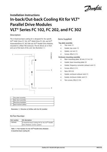
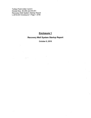
Turkey Point Units 3 and 4Docket Nos. 50-250 and 50-251Recovery Well System Startup ReportFPL Turkey Point Recovery Well System startup ReportOctober 2018L-2019-031 Enclosure 1Page 11 of652. Recovery Well System2. RECOVERY WELL SYSTEMThe Turkey Point RWS includes 10 groundwater recovery wells, a conveyance pipeline system,and a deep injection well (DIW) (Figure 2.1-1). The recovery wells are designed to extracthypersaline groundwater preferentially along the base of the Biscayne Aquifer. The shallow andintermediate zones of the Biscayne aquifer in each recovery well are cased off, thereby allowinghypersaline groundwater to be pulled from the high-flow zones. of the lower portion of theBiscayne aquifer. Accordingly, recovery well depths vary from 90 to 105 feet (ft) below groundsurface, with wells casings set approximately 25 ft above the bottom. Table 2.1-1 provides thelocation of each recovery well and construction details (i.e., depth, casing sizes, boreholediameter).Each recovery well is equipped with a line shaft turbine pump powered by a 150-horsepowerelectric motor with a capacity of approximately 2 million gallons per day (mgd). The currentR WS has a permitted withdrawal allocation of 15 mgd, with each well set to withdraw 1.5 mgdofhypersaline groundwater. A Supervisory Control and Data A quisition (SCA.DA) systemprovides centralized operation of the RWS and has the capability to monitor and regulateindividual well withdrawal rates and maintain total extraction capacity in the event ofindividual well fluctuations based on manual or programed operational protocols. Figure 2.1-2shows a typical recovery well with pump motor and valves. Further details regarding therecovery wells, pumps, motors, and appurtenances are found in Appendix A. Geophysical logsfor the recovery wells are provided in Appendix B.Hypersaline groundwater pumped from each recovery well is routed through a 14-inchdiameter high-density polyethylene (HDPE) pipe to a main 28-inch header pipeline. Theheader pipeline network connecting all of the RWS extraction wells to the DIW areapproximately 9 miles long (Figure 2.1-1 ). All piping is buried for protection; a photograph ofthe header pipeline during construction is shown on Figure 2.1-3. Further details on thepipeline system and specifications are included in Appendix A.The DIW is located near the center of the Cooling Canal System (CCS) (Figure 2.1-1). TheDIW is a 24-inch-diameter permitted Underground Injection Control (UIC) non-hazardousClass I industrial wastewater disposal well (Permit No. 0293962-004-U0/11) constructed to adepth of 3,230 ft below ground surface into the regionally confined Boulder Zone. Figure 2.1-4shows the DIW wellhead, appurtenances, and well construction details. Monitoring of the DIWis conducted in part, via a dual-zone monitoring well, pursuant to permit conditions (Figure 2.15).The assessment of progress made in meeting the objectives of the FDEP Consent Order and theMDC Consent Agreement hypersaline groundwater remediation is informed, in part, by a seriesof existing and newly added monitoring wells. New RWS monitoring well clusters TPGW-17,TPGW -18, and TPGW -19 were constructed west of the CCS pursuant to paragraph 17 .d.iv. ofthe Consent Agreement to monitor progress of the retraction of the hypersaline plume. Three2-1
Turkey Point Units 3 and 4Docket Nos. 50-250 and 50-251Recovery Well System Startup ReportFPL Turkey Point Recovery Well System Startup ReportOctober 2018L-2019-031 Enclosure 1Page 12 of652. Recovery Well Systemseparate wells were installed at each location: a shallow well (S), located in the upper high-flowzone of the Biscayne aquifer; an intermediate depth well (M) in the middle high-flow zone; anda deep well (D) along the base of the aquifer. The borehole for the deep well was drilled first,and down-hole geophysical methods were used to help determine high-flow zones and othersubsurface characteristics. Screen depths were established, with screen lengths varying from 2to 5 ft, based on site conditions, to ensure high-flow zones at each depth were being monitored.Appendix C provides further details on these three new monitoring well clusters.All monitoring wells, recovery wells and the DIW are equipped with automated probes (In SituLT500 and ATlOO probes or Hach 3700) that allow the collection of hourly water level,temperature, specific conductivity, salinity, and density data. In addition, the monitoring wells,RWS extraction wells, and inflows into the DIW are sampled for select analytic water qualitydata ranging from weekly to monthly frequencies. All data required under the provisions of theMDC Consent Agreement are collected, processed, and quality controlled under the approvedTurkey Point Quality Assurance Project Plan (QAPP). Provisional quality assurance(QA)/quality control (QC) data and associated documentation are posted on an FPL databaseand provided to MDC, FDEP, and the South Florida Water Management District (SFWMD) inannual reports. Provisional water quality and water level data collected during the first quarterofRWS operations are discussed in Section 3 of this report.2-2
Turkey Point Units 3 and 4Docket Nos. 50-250 and 50-251Recovery Well System Startup ReportFPL Turkey Point Recovery Well System Startup ReportOctober 2018TABLESL-2019-031 Enclosure 1Page 13 of652. Recovery Well System
Turkey Point Units 3 and 4Docket Nos. 50-250 and 50-251L-2019-031 Enclosure 1Page 14 of 65Recovery Well System Startup ReportFPL Turkey Point Recovery Well System Startup ReportOctober 20182. Recovery Well System. - - --- r--- ---r- --r'i Compo,.,,.,,-,"'-----1h . '"'"PVC""'" Comp'"'" F:';::o !:: :.i[c,mp'"'' Opo,aaraT bl 211wR,I, .\IY ':11 u!11b!: .RWS-1RWS-2RWS-3 (APT :s'"oora!1!-'.1t!!u e .ft1: !-o EJ!t ! 52-80.36754-80.36759I"" ,,'"''"''1'I Steel Surface Casingl Well Casing Set I bis) Nominal 24- Ii (production zone;Ii Set l?: t!J ! f e sJ J - pth ( f:e t b!s) :I )nch ?ring !1 fe:!L ]40404940505040404040NOTE:*RW-4 was constructed with an 18-inch final well casing.Key:bis below land surfaceAPT aquifer performance 5301826262531252020
Turkey Point Units 3 and 4Docket Nos. 50-250 and 50-251Recovery Well System Startup ReportFPL Turkey Point Recovery Well System Startup ReportOctober 2018FIGURESL-2019-031 Enclosure 1Page 15 of652. Recovery Well System
Turkey Point Units 3 and 4Docket Nos. 50-250 and 50-251Recovery \Nell System Startup ReportFPL Turkey Point Recovery Well System Startup ReportOctober 2018 RecoveryWelltiMonitoring WellL-2019-031 Enclosure 1Page 16 of652. Recovery Well System- - RWS pipelineFigure 2.1-1. Location and Layout of Recovery Well System and Mo nitoring Wells .2-4
Turkey Point Units 3 and 4Docket Nos. 50-250 and 50-251Recovery Well System Startup ReportFPL Turkey Point Recovery Well System Startup ReportOctober 2018Figure 2.1-2. A Typical Recovery Well with Pump Motor and Valves .2-5L-2019-031 Enclosure 1Page 17 of 652. Recovery Well System
Turkey Point Units 3 and 4Docket Nos. 50-250 and 50-251Recovery Well System Startup ReportFPL Turkey Point Recovery Well System Startup ReportOctober 2018Figure 2.1-3. HOPE Header Pipeline Installation.2-6L-2019-031 Enclosure 1Page 18 of 652. Recovery Well System
Turkey Point Units 3 and 4Docket Nos . 50-250 and 50-251L-2019-031 Enclosure 1Page 19 of 65Recovery We ll System Startup ReportFPL Turkey Point Recovery Well System Startup ReportOctober 20182. Recovery Well SystemPrellmlnary DealgnNot for Conatructlon--,At ---- -- .,.tr OONalmi P'Clfl:OMINAGITO . . . ----- ----- --DEEP INJECTION WELL DIW-1 PLAN I;DiDEEP INJECTION WELL DIW-1 WELLHEADDETAIL@I!DEEP INJECTION WELL DIW-1SECTION AA- -·Iii1iIIOWIW 11. . . . . .Legend:FPLDEEP INJECTION,,., WELL PROJECT a.thUT. T.,.,R.ms7www.cam (113)1112: tlOOFlgure1Deep Inj ection WellT-.t.yPoil"ltNudNf'Ptlwt"'t7IO 1W 344tti . . . .J:PI. HomlrltNd, R. 33035C.,. XIOOOOOC I FMilW IDCW11MENERCON,-.r.,.c-.11M11 .a.1J1t XIOOOOOOtFigure 2.1-4. Turkey Point DIW-1 Injection Well.2-7Surface Features DIW-1Project No: NEETPX140
Turkey Point Units 3 and 4Docket Nos. 50-250 and 50-251L-2019-031 Enclosure 1Page 20 of 65Recovery We ll System Startup ReportFPL Turkey Point Recovery Well System Startup ReportOctober 20182. Recovery Well System.-------\---Preliminary DesignNot for Construction,OMr.llmClOJIDIIID, .,., \IJltl.W:.lWJIIIIIIWCI-.--trirr.a MU.Wll. lOMlAMIXRIUItr-;-.,.ttl.MI.LWILW'MTM.,.Nl'WtC ., , t C:):::l)A- --------------- - \' \\C[fl\' \\DUAL ZONE MONITORING WELL DZMW-1 PLAN ISection DD t!IfDUAL ZONE MONITORING WELL DZMW-1 WELLHEADDETAIL@DUAL ZONE MONITORING WELL DZMW-1SECTION AAImv,1I1iIIm. FPLDEEP INJECTIONWELL PROJECTT'*YPQinl Plll'll91&0 SW MClh 8i'Mtl P&. HomNtNd, R. 3303!5C-- D00000C I Rlat\' ID a lOOOOOCXXFigure 2. 1-5. Turkey Point DIW-1 Dual Zone Monitoring Well.2-8ENERCONLegend:--9hNt2 aut 21D8T""'* Olllalltwd , 9ull 13tT. . . Tanace,Fl331137- --et'l9IOIM'l.coM (113)112-1800!.llc:nlalConlUFlgure2.Dual Zone Monitoring WellSurface Features DZMW-1Pro"ect No: NEETPX140
Turkey Point Units 3 and 4Docket Nos. 50-250 and 50-251Recovery Well System Startup ReportL-2019-031 Enclosure 1Page 21 of 65FPL Turkey Point Recovery Well System startup ReportOctober 20183. Recovery Well System Baseline Data and First Quarter of Operation3. RECOVERY WELL SYSTEMBASELINE DATA AND FIRSTQUARTER OF OPERATIONFPL conducted a baseline CSEM survey and collected groundwater data from the recovery wellsand select monitoring wells prior to RWS startup (baseline groundwater data) and for the firstquarter of operation, consistent with the MDC letters dated September 29, 2016, and May 15,2017. This section presents the baseline information, a summary ofRWS monitoring data andoperation, and a discussion of influence of the RWS on groundwater and impacts to adjacentwetlands during the first quarter of operation.3.1 Baseline Monitoring ResultsFPL collected baseline groundwater samples between March 13, 2018, and April 3, 2018, fromnew monitoring well clusters TPGW-17, TPGW-18, and TPGW-19, historical well clust rsTPGW-1, TPGW-2, TPGW-4, TPGW-5, TPGW-7, and TPGW-12, and historical individualwells TPGW-L3, TPGW-L5, TPGW-G21, and TPGW-G28 (Figure 3.1-1). Field parameters(temperature, specific conductance, salinity, density, and total dissolved solids [TDS]) weremeasured and samples were collected for laboratory analysis of tritium and chloride at each ofthe wells/well clusters. Groundwater levels were also measured during sampling. The resultsare presented in Table 3.1-1. Groundwater sampling logs from the March 2018 sampling eventare provided in Appendix D of this report. Data usability summary (DUS) reports for the eventare provided in Appendix E, and the Level IV laboratory reports are included in Appendix F.Samples were collected at discrete screen intervals from the shallow, intermediate, and deepwells at TPGW-1, TPGW-2, TPGW-4, TPGW-5, TPGW-7, TPGW-12, TPGW-17, TPGW-18,and TPGW-19 well clusters. The historical individual wells, TPGW-L3, TPGW-L5, and TPGWG21, are continuously screened across the formation; the exception is TPGW-G28 which is hardcased to 18 ft below the top of casing. These individual well samples were collected at 18 ft and58 ft below top of casing. Samples from the groundwater well clusters were collected usingdedicated tubing, and all samples were collected per the methods outlined in the QAPP (FPL2013) and FDEP Standard Operating Procedures (SOPs).All sites, besides TPGW-17, TPGW-18, and TPGW-19, have a long-term record of quarterlywater quality data dating back to 2010. There are also automated water elevation, specificconductance, temperature, and salinity data collected at 15-minute to 1-hour intervals since 2010except for the three new well clusters which have a shorter period of record and TPGW-L3,TPGW-L5, TPGW-G21, and TPGW-G28 which are not equipped with automatedinstrumentation. Table 3.1-2 shows baseline groundwater elevations at a specific point in timefrom the different monitoring locations. As the individual wells do not have automatedinstrumentation, the closest temporal field measurements from these sites were used.3-1
Turkey Point Units 3 and 4Docket Nos. 50-250 and 50-251Recovery Well System Startup ReportL-2019-031 Enclosure 1Page 22 of65FPL Turkey Point Recovery Well System Stattup RepottOctober 20183. Recovery Well System Baseline Data and First Quatter of OperationHourly automated groundwater water level data show groundwater levels are influenced by tidalcycles to varying degrees as well as rainfall, dry periods, and density of the waters within thesampled horizon. Accordingly, area groundwater elevations vary temporally (throughout eachday due to tidal influences as well as daily, weekly, and seasonally) and vertically (within the. aquifer due to variations in salinity) at any given sample site.3.2 CSEM Baseline SurveyAs outlined in Section 3b of the MDC letter dated May 15, 2017, and paragraph 29(a) of theFDEP Consent Order, FPL conducted a baseline CSEM survey to map the extent and orientationof the hypersaline groundwater plume west and north of the Turkey Point Plant. The survey wasconducted in late March/early April 2018 (within 60 days ofRWS startup) and encompassedapproximately 30 square miles to the west and north of the CCS, including an area beneath theedge of the CCS and the FPL property boundary and an area north and northwest of the CCS.The survey was performed using a helicopter equipped with a transient electromagnetic method(TEM) transmitter and receiver system. The TEM system measures the bulk resistivity ofspecific depths of earth materials and associated groundwater. Chloride concentrations ofgroundwater were inferred from the resistivity values derived from the TEM data via the processillustrated in Fitterman and Prinos (2011) as described in the PTN Cooling Canal Systemelectromagnetic geophysical survey report (ENERCON 2016). 3D voxels (discrete cells ofspecific chloride concentration) were created based on the vertical and horizontal discretizationof the TEM data and extend from the land surface to the base of the Biscayne Aquifer (Fish andStewart 1991) and west and north of the FPL property, as defined in the MDC ConsentAgreement. The report summarizing the 2018 baseline survey and results is provided inAppendix G.In addition to mapping groundwater with chloride concentrations greater than 19,000milligrams per liter (mg/L), FPL evaluated the CSEM method to identify a reliable lower limit ofchloride estimation for mapping. As the chloride ion content of pore waters in the BiscayneAquifer decreases, the influence of porosity variations on the bulk conductivity of thebedrock/pore water combination increases. At some lower limit of chloride ion content, thegeologic noise from porosity variations becomes too large for reliable mapping of chloride ioncontent using the CSEM method. To determine the lower limit for reliable mapping of chlorideion values, the accuracy of predicting pore water chloride ion values for waters with chloridelevels 19,000 mg/L was compared to the accuracy of mapping chloride for waters 19,000mg/L. The evaluation indicated that the average CSEM chloride ion prediction error is about thesame for pore waters with chloride ion contents 10,000 mg/L as for pore waters with chlorideion contents 19,000 mg/L. However, prediction accuracy decreases significantly for pore waterchloride ion contents 10,000 mg/L. Based on this analysis, the reliable lower limit of theCSEM TEM survey for mapping chloride ion content within the Biscayne Aquifer is 10,000mg/L.The CSEM survey determined that the maximum westward extent of the hypersalinegroundwater, as defined by chloride concentrations in excess of 19,000 mg/L west and north ofthe FPL property (MDC September 29, 2016), is approximately 16,000 ft west of the western3-2
Turkey Point Units 3 and 4Docket Nos. 50-250 and 50-251Recovery Well System Startup ReportL-2019-031 Enclosure 1Page 23 of65FPL Turkey Point Recovery Well System Startup ReportOctober 20183. Recovery Well System Baseline Data and First Quarter of Operationboundary of the CCS at a depth of 47 to 55 ft. The plume does not extend as far west atshallower and deeper depths, indicating that the hypersaline plume is wedge-shaped, with the tipof the wedge at about 55 ft below land surface. At both shallower and deeper depths, the plumedoes not extend as far west. The presence of hypersaline water at the base of the BiscayneAquifer (87.0 to 99.4 ft below land surface) extends only about 5,600 ft westward from the CCS.The baseline volume of the material with chloride concentrations greater than 19,000 mg/Lwithin the compliance area west and north of the FPL property as identified in the MDC ConsentAgreement is estimated to be 450,493,000 cubic meters (m 3). The estimate sums the volume ofeach model cell within the 3D voxel model having an estimated chloride concentration of 19,000mg/Land greater.3.3 First Quarter of Operation Monitoring ResultsFPL collected samples from the recovery and monitoring wells that were used for the baselinesampling consistent with the startup monitoring included in the MDC May 15, 2018, letter. Fieldparameters (temperature, specific conductance, salinity, density, and TDS) and samples forchloride analysis were collected weekly for the first month of operation (startup through June 15,2018) and then once a month in July and August 2018. Samples from the recovery wells werecollected from dedicated sampling ports, while samples from groundwater monitoring wells werecollected using peristaltic pumps, with most wells having dedicated sample tubing. All sampleswere collected per the methods outlined in the QAPP (FPL 2013) and FDEP SOPs provided inChapter 62-160, Florida Administrative Code (F.A.C.).The chloride results from the recovery wells during the first quarter sampling period showchloride levels in each of the recovery wells were stable, with minor fluctuations within a narrowrange (Table 3.3-1). During the first quarter, chloride values typically varied by less than 5%;'however, RWS-1 did exhibit more variability than the other wells. Recovery well RWS-1 alsohad the lowest overall average chloride concentration (22,857 mg/L), while RWS-5 had thehighest average concentration (31,086 mg/L). Chloride concentrations in the monitoring wells(Table 3.3-2) showed a similar pattern as the recovery wells i.e. most of the chlorideconcentrations in the monitoring wells fluctuated within a narrow range of values. The samplinglogs for the first quarter of monitoring are provided in Appendix D. The DUS reports areprovided in Appendix E, and the Level IV laboratory reports are included in Appendix F.Automated water level and water quality (specific conductance, salinity, temperature, anddensity) data were
Docket Nos. 50-250 and 50-251 Recovery Well System Startup Report FPL Turkey Point Recovery Well System Startup Report October 2018 EXECUTIVE SUMMARY L-2019-031 Enclosure 1 Page 9 of65 Executive Summary Florida Power & Light Company (FPL) successfully initiated operations of the Turkey Point Recovery Well System (RWS) on May 15, 2018.