Transcription
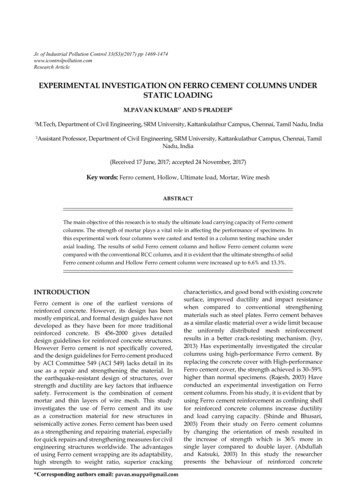
Engineering Structures 33 (2011) 2237–2247Contents lists available at ScienceDirectEngineering Structuresjournal homepage: www.elsevier.com/locate/engstructModel-based design and experimental validation of active vibration control for astress ribbon bridge using pneumatic muscle actuatorsAchim Bleicher a, , Mike Schlaich a , Yozo Fujino b , Thomas Schauer caDepartment of Civil and Structural Engineering, Berlin Institute of Technology, Berlin, GermanybBridge & Structure Laboratory, Department of Civil Engineering, University of Tokyo, Tokyo, JapancControl Systems Group, Department of Electrical Engineering and Computer Science, Berlin Institute of Technology, Berlin, GermanyarticleinfoArticle history:Received 20 September 2010Received in revised form26 January 2011Accepted 28 February 2011Available online 24 May 2011Keywords:Active vibration controlLightweight structureStress ribbon bridgePedestrian-induced vibrationPneumatic muscle actuatorState feedback controlabstractThis paper describes the development of an active vibration control system for a light and flexible stressribbon footbridge. The 13 m span carbon fiber reinforced plastic (CFRP) stress ribbon bridge was builtin the laboratory of the Department of Civil and Structural Engineering, Berlin Institute of Technology.Its lightness and flexibility result in high vibration sensitivity. To reduce pedestrian-induced vibrations,very light pneumatic muscle actuators are placed at handrail level, introducing control forces. First, areduced discretized analytical model is derived for the stress ribbon bridge. To verify the analyticalprediction, experiments without feedback control are conducted. Based on this model, a delayed velocityfeedback control strategy is designed. To handle the nonlinearities of the muscle actuator, a subsidiaryforce control is implemented. Then the control performance from numerical simulation is verified byexperiments under free vibration. As a result, analytical analyses agree well with experimental results. Itis demonstrated that handrail-introduced forces can efficiently control the first mode response. 2011 Elsevier Ltd. All rights reserved.1. IntroductionStress ribbon bridges are among the most elegant and lightestbridges. Due to their static and dynamic characteristics, they havebeen mainly designed for pedestrian traffic rather than for roador rail traffic [1,2]. The suspension cable and the bridge deckare combined into one stiffening element, which is anchored inthe abutments. Usually, the cables are made of steel cables orsteel plates. To show the potential of high-strength carbon fiberreinforced plastics (CFRPs), a 13 m span stress ribbon bridge withCFRP ribbons was built in the laboratory of the Department ofCivil and Structural Engineering, Berlin Institute of Technology(TU Berlin); see Fig. 1. This composite material allows considerablysmaller cross sections compared to steel. The bridge’s tensile forceunder dead and live load is carried by only 6 ribbons with a crosssection of 1.1 mm 50 mm each. The combination of lowextensional stiffness using CFRP for the ribbons and a lightweightbridge deck leads to considerable dynamic responses caused bypedestrian loads [3,4].Generally, to keep vibrations within acceptable limits, severalconceptual design approaches such as increasing the stiffnessor increasing the dead load/traffic load ratio have been applied Corresponding author.E-mail address: Achim.Bleicher@gmx.de (A. Bleicher).0141-0296/ – see front matter 2011 Elsevier Ltd. All rights reserved.doi:10.1016/j.engstruct.2011.02.035in practice. Sometimes, additional passive dampers have beeninstalled to reduce high vibrations [5–8].An alternative potential approach to ensure the structuralserviceability respectively comfort criteria of footbridges is to useactive vibration control (AVC). In particular, this is necessary forextremely light structures, where system properties such as themass and stiffness become time-variant with changing pedestriantraffic. Then the natural frequencies start to depend on live loadsand some passive damping techniques can no longer operateoptimally.In civil engineering structures, active vibration control hasbeen achieved and implemented by active mass dampers (AMDs)or hybrid mass dampers (HMDs) in towers, tall buildings, andpylons of cable-stayed bridges. Controllable fluids such as electrorheological (ER) and magneto-rheological (MR) ones have beenused as semi-active dampers to control wind-induced cablevibrations and buildings under earthquake excitations [9–11].Studies on the active control of cable vibrations have beenconducted in [12–14]. By axial support movements, sag-inducedforces can be applied which change the cable tension and controlthe in-plane vibrations. Experimental studies have confirmed thiscontrol strategy, limited to the symmetric modes and efficient onlyfor the first in-plane mode.The applied concept of active vibration control for the stressribbon bridge is to control the symmetric modes as well asthe asymmetric modes. The natural frequencies of the CFRP
2238A. Bleicher et al. / Engineering Structures 33 (2011) 2237–2247Fig. 1. Carbon fiber reinforced plastic stress ribbon bridge at TU Berlin.Fig. 2a. Concept of active vibration control (set-up B).Fig. 2b. Set-up A.stress ribbon bridge that coincide with the dominant frequenciesof pedestrian-induced loads range from 1.34 to 3.75 Hz dueto walking, running, and jumping [4]. To reduce the dynamicresponses in this range, control forces are introduced at handraillevel by very light pneumatic muscle actuators (PMAs) placed atthe midspan and quarter points (Fig. 2a, set-up B). The handrailposts are rigidly coupled with the concrete slabs and pin-jointedwith each other, except for the actuator placement. In thisway,control forces can be applied along the bridge deck to producea countermovement.In this study, one pair of actuators mainly controlled by onesensor is considered. The actuators are placed between twohandrail posts on each side at the midspan, and the sensor isplaced at the midspan in the centre line (Figs. 2b, 3a and 3b).This actuator/sensor configuration (set-up A) allows control of thesymmetrical modes. The control system presented here focusesonly on the first symmetric mode. To design a model-basedcontroller, an analytical control-orientated model is derived forthe bridge in Section 2. The nonlinear force contraction behaviorof the extremely light pneumatic muscle actuator is describedin Section 3. In Section 4, modal state control strategies areinvestigated, and a subsidiary force control is proposed to handlethe nonlinearities of the pneumatic actuator. The efficiency of theobtained control designs is tested by numerical simulations andverified by full-scale experiments focusing on free vibrations inSection 5.Fig. 3a. Experimental set-up A.2. Analytical model for multi-modal motions2.1. Parameters of the bridge and the derived eight-plate modelFrom the distributed system of the stress ribbon bridge, ananalytical plane rigid body model for a multi-variable controlFig. 3b. Actuator and reference sensors.
A. Bleicher et al. / Engineering Structures 33 (2011) 2237–22472239Fig. 4. The eight-plate model (set-up A).system is developed. In order to get good agreement with experimental data for the modes to be controlled, a plane model withseven degrees of freedom qi is developed (Fig. 4). The stiffeningeffect of the railing is not included, as its influence on the modes tobe controlled is negligible (Table 3).The deck of the bridge consists of six CFRP ribbons, which arecovered by 16 open-jointed concrete plates in two sizes—12 longplates (0.8 m) and 4 small plates (0.6 m). To simplify the modeling,eight equal-sized plates with a length L 1.63 m are discretized.The single model plates are pin-jointed and form a sprocketchain. The total mass of the real bridge including the railing isMT 4336 kg. Using uniform distribution, the weight of eachmodel plate ismi MT /8 542 kg {i 1 . . . 8}.(1)The moment of inertia is calculated as follows:Iyyi 1/12 · mi · (L2 d2 ) 120 kg · m2{i 1 . . . 8}.(2)The parameters are listed in Table 1.The bearing conditions at the two ends of the chain are fixedin the vertical direction and elastic in the horizontal direction. Theelastic flexibility is modeled by horizontal springs. These springsrepresent the extensional stiffness of the CFRP ribbons, which arenot modeled themselves. Hence, it can be assumed that the elasticelongation of the CFRP ribbons occurs only discrete at the bearings.The spring stiffness is calculated by the extensional stiffness EAresulting from six CFRP ribbons.k EA/(LT /2) 7 356 000 N/m.(3)The effect of high elastic elongation using high-strength materialshas to be taken into account for design and construction. To obtainthe desired geometry under dead load, the CFRP ribbons had tobe pre-stressed before they were covered with concrete plates.The state under pre-stressing without dead load is the initial statefor model formulation, and it corresponds with the horizontal waxis in Fig. 4. The equivalent pre-stressing force P in the model isapplied at each bearing.P 300 000 N.(4)After the ribbons were covered with the concrete plates, the bridgegot its shape due to elastic elongation. The geometric stiffnessof the bridge results from the tensile force in the ribbons in thissagged state.The structural damping is derived from measured free vibrations. As the railing has an influence on structural damping, themeasurement was done under bridge set-up A. To determine thelogarithmic decrement Λi of the i-th mode (Table 2), the measuredsignals (accelerations) were filtered. Then the modal damping ratio is calculated by ζi Λi /2π and the damping coefficient Ci isgiven byCi 2 · ζi · Mi · ωi .(5)The modal mass Mi is obtained by modal transformation, asdiscussed in Section 3. In Eq. (5), ωi is the natural angular frequencyof the i-th mode of the eight-plate model (Table 3).Table 1Parameters of the bridge and input parameters for the eight-plate model.ParameterTotal bridge length (m)Plate length (m)Plate thickness (m)Total mass (kg)Plate mass (kg)Mass moment of inertia (kgm2 )Stiffness of CFRP ribbon (MN)Spring stiffness (N/m)Pre-stressing force (N)LTLdMTmiIyyiEAkPBridgeEight-platemodel13.054 0.60/12 0.800.1043364 220/12 2884 6.8/12 15.74813.058 1.630.1043368 5428 1207 356 000300 000300 000Table 2Modal damping values of the bridge, set-up A.ModeNo.Log decrement ΛiModal damping ratio (%)Vertical symmetricVertical asymmetricVertical symmetricVertical asymmetricVertical symmetricVertical asymmetricVertical 060.00260.220.400.660.260.680.810.042.2. Model formulation2.2.1. Constraints/generalized coordinatesThe bridge model consists of N 8 discrete masses with p 16geometric constraints. Using Eq. (6), the number nq of degrees offreedom or the generalized coordinates qj can be calculated.nq 3N p.(6)The horizontal degree of freedom can be neglected as it is decoupled from the interesting vertical movement and cannot be controlled by the actuator placement. Finally, seven vertical degreesof freedom (respectively, generalized coordinates, qj ) remain. Forthe generalized coordinates qj , the pin-joint coordinates are chosen, except at the abutments. The expression for qj appears as Eq.(7), given in Box I.The geometric relation between the elastic and geometricstiffness and the coordinates is nonlinear. Therefore, a smallangle approximation is used. The cosine function is approximatedby using a Taylor series development with truncation of theseries after the second term: cos θi 1 1/2θi2 . Considering theconstraints, the following coordinates for model formulation areused, according to Fig. 4.zi θi 121L(z i z̄i ) {i 1 . . . 8}(8)(z i z̄i ) {i 1 . . . 8}(9)
2240A. Bleicher et al. / Engineering Structures 33 (2011) 2237–2247 q q1q2q3q4q5q6 T z̄1q7 z2z̄2z̄3z̄4z̄5z3z4z5z6 T Tz̄7z̄6z7(7)z8Box I.Table 3Calculated natural frequencies of the eight-plate model and experimentally identified natural frequencies of the bridge without railing, set-up A and set-up B. The regardedfrequencies are grayed.Eight-plate modelModeNo.Bridge without railingBridge set-up ABridge set-up BNatural frequencies fi (Hz)Vertical symmetric11.331.34 0.8%1.35 1.5%1.32 0.8%vertical asymmetric22.542.48 2.4%2.76 8.7%2.45 3.5%vertical symmetric33.853.75 2.6%4.08 6.0%3.76 2.3%vertical asymmetric45.344.985.534.89vertical symmetric56.986.327.086.64vertical asymmetric68.677.538.608.65vertical symmetric710.098.749.439.78 0.21 0.21 0.21Operating point (m) 0.21x7,0w1 4 12i 1w̄8 θ2i L8 1i 52 (10) θi2 L .(11)2.2.2. Lagrange’s equations of motionLagrange’s equations of the second kind for non-conservativesystems with holonomic constraints are employed to derive theequations of motion. The Lagrange equations [15] can be expressedasd dt L q̇j L Qj qj{j 1 . . . 7},material damping, structural damping (mechanical connections), and damping due to bearing conditions. To consider thedifferent damping mechanisms in a model, they have to be identified. As identification is complex, damping is considered bymodal damping using modal transformation, as shown in Sections 2.1 and 4.1. A phenomenological approach to considerfriction forces in the Lagrange equations can be found in [15].3. Non-conservative forces from active control introduced athandrail level in the midspan are defined by(AC1 )Qj(13)T 8 1/2mi żi2 i 18 1/2mi ẇi2 Iyyi θ̇i2 .(14) θi qj wi (qj ) Fwi · Fθi · qj qji 1{j 1 . . . 7}(19)Fwi Fwi (AC1 , θi )(20)Fθi Fθi (AC1 , θi , h),(21)where AC 1 is the active control force generated by twopneumatic muscle actuators at the midspan (Section 4). Thevertical component of AC 1 is neglected.Using the Lagrange equations, seven nonlinear ordinary differential equations (ODEs) of second order can be derived.i
3. Physical model of a pneumatic muscle actuator (PMA) ld theareaof stheir extremelylowself