Transcription
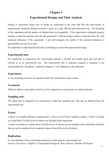
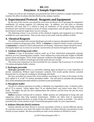
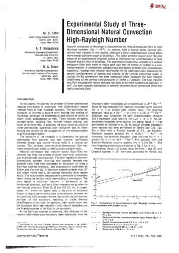
M. S. BohnSolar Energy Research Institute,Golden, Colo . 80401Assoc . Mem . ASMEA. T; KirkpatrickMechanical Engineering Depanment.Colorado State University,Ft. Collins. Colo .Assoc. Mem. ASMED. A. OlsonMechanical Engineering Depanment,Massachusetts Institute of Technology,Cambridge , Mass.Assoc . Mem . ASMEExperimental Study of ThreeDimensional Natural ConvectionHigh-Rayleigh NumberNatural convection in Uuildings is characterized by three-dimensional f lo w at highRayleigh numbers (Ra - 1010 ) . At present, li11le is known about natural convection hear transfer in this regime, although a better understanding would allowmore energy efficient usage of buildings. This paper presents results f rom the f irstphase of an experimental program aimed at improving our undersranding of heattrans/ er and air flo w in buildings. The experimental apparatus consists of a cubicalenclosure filled with water in which each wall may be heated or cooled in a controlled manner. A transparent, adiabatic top and bouom provide flow visualizationcapability. Average heat transfer coefficients f or the wofls have been measured forseveral config urations of heating and cooling of 1he verrical isothermal wafls. Aunified N u-Ra correlation has been computed which collapses 1he heOI Irons/ercoefficienls of lhe various configurarions 10 within 5.7 percent. The heat transferand flo w uisua/iza1ion resul1s indicate that euen at Rayleigh numbers as high as 6 x10 10 , the hear transfer mechanism is laminar boundary-layer con vection from onewall to rhe bulk fluid.IntroductionIn this paper, we address the problem of three-dimensionalnatural convection in enclosures with differentially heatedverrical walls at high Rayleigh numbers. The particular application of interest is passive solar heating and cooling ofbuildings, although the experimental data should be useful inmany other applications as well. These include cryogenicstorage tanks , building fires, nuclear reactor cooling, andsolar cavity receivers. ln addition, the data should be useful inthree-dimensional numerical code validation and in determining the validity of the assumption of two-dimensionalityin previous experiments .The objective of the research is to determine the naturalconvection flow patterns and heat transfer coefficientsbetween heated and cooled vertical walls in a cubical enclosure. This problem involves three-dimensional flow between perpendicular walls, as well as across parallel walls.Natural convection heat transfer across fluid-filled enclosures has been the subject of many analytical, numerical,and experimental investigations. The flow regimes in the twodimensional problem involving heat transfer between twoparallel walls were first delineated by Batchelor [l] using aRayleigh number criterion, and subsequently confirmed byEckert and Carlson [2). At Rayleigh numbers greater than 104and aspect ratios near 1, the laminar boundary layer regimeexists . The heat transfer mechanism is convection in boundarylayers along the vertical walls surrounding a core region. Thecore region is relatively inactive, is isothermal in thehorizontal direction , and has a linear temperature gradient inthe vertical direction. Elder [3 , 4) and Gill [5), for A, aspectratios 1, where the aspect ratio is the ratio of enclosureheight to length, have shown there is entrainment between thehot and cold wall boundary layers, due to the top and bottomsurfaces of the enclosure, resulting in stable thermalstratification of the core. In addition, their results show thatthe boundary layer heat transfer is only weakly dependent onthe Prandtl number of the fluid in the enclosure.As the Rayleigh number is increased, the thickness of thevelocity and temperature boundary layers decreases, since theContr ibuted b y the Hear Transfer Di visi o n and presented ar the ASME·JSME Joint Th erm a l Engineering C onrerence . Honolulu. Hawaii . Marc h 1983 .Manuscript rece ived by the Heal Transfer Division Ma y 2. 1983.Journal of Heat TratasferllllllWBllWl!ll"""'IW!'"11M"!l'l'li! ftltMll!"!s ""l'?"""''·''7"'' . -.--· ---··-··boundary layer thicknesses are proportional to A 114 Ra - 114 Bejan [6] has extended Gill 's laminar boundary layer solutionfor A 1 to predict heat transfer rates. The resultingequation, valid as A Ra 117 - oo is Nu 0.364 A - 114 Ra 114 .Simpkins and Dudderar [7] have experimentally checkedGill ' s boundary layer analysis for 0.25 A 9. An approximate boundary layer analysis for aspect ratios 5 wasperformed by Raithby et al. (8, 9), and an integral boundaryla yer analysis has been perfo rmed by Emery and Chu [10).For a fluid with a Prandtl number of 3 .5, the RaithbyH oll ands anal ysis predicts Nu 0 .335A - 114 Ra 114 Insummary, the previous boundary layer analyses for A 1predict Nu (.3 to .4) A - 114 Ra 114 For turbulent flow, theRaith by-Hollands analysis predicts Nu 0.044 Ra 113 Thetwo foregoing predictions are plotted in Fig . I for A 1.Numerical results for aspect ratios between I and 20, andGrashof number 10 5 have been presented by Newell and""'100l,. . I.10'. .'.10"Fig . 1 Compilation ot !WO·dimensional high Aayleigh number dataand c:omparison with present resu l tsRaith b y·H2llands laminar boundary layer theory (9), A :s 1,Pr3.5Ralthby·Hollands turbulenl boundary layer theory (9), A "'1, Pr 3.5Gadgil numerical analysis (23), A 1, Pr 0.7Bauman et al. (27), A "' 0.5, Pr3.5Nansteel and Greif (29), A0.5, Pr 3.5Burnay et al. (181, .41, Pr 0.7 o MAY 1984, Vol. 106 / 339
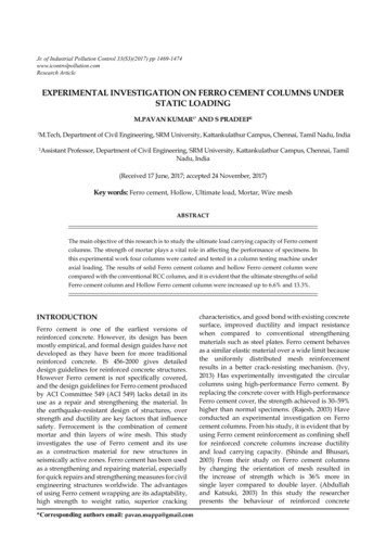
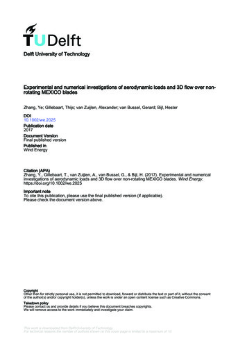
Schmidt [II] for aspect ratios between 0.1and20, by Boyackand Kearney [12] and aspect ratios between 0.05 and 1, andRa 10 6 by Inaba et al. [13]. Numerical results for Ra 10 1and aspect ratios of I, 5, and 10 have been computed byStrada and Heinrich [14]. The numerical results predict amaximum Nusselt number near an aspect ratio of one, and asthe aspect ratio approaches zero or infinity, the Nusseltnumber approaches unity, a trend also noted by Bejan [15].Also, as the Rayleigh number is increased, the aspect ratio atwhich the maximum Nusselt number occurs decreases. lnlnaba's [13] numerical analysis, the aspect ratio at which theNusselt number was a maximum decreased from A 1.7 atRa 10 4 to A 1.2 at Ra 10 5 Bejan (15] predicted thatthe maximum Nusselt number would occur at A 0.4 for Ra 10 6 ;A 0.25toRa 10 1 ;andA 0.18atRa 10 8 The data (from an experiment with A 0.5) plotted on Fig. Ifollow the same trend, since they lie above the A Ipredictions.Limited two-dimensional experimental data exist for Ra 10 8 and A near I. MacGregor and Emery (16] found experimentally for constant heat flux conditions and aspectratios from 10 to 40 that Nu 0.42 A -o. 3 Pr 0 012 Ra 114 for 3x 10⁴ Ra 3 x 10 6 and Nu 0.046 Ra 113 for 3 x 10 1 Ra 10 9 For the aspect ratios of their experiment, theydetermined that the transition from fully laminar to fullyturbulent boundary layer flow occurred in the range ofRayleigh numbers from 3 x 10 6 to 3 x I0 1 Dropkin andSommerscales (17] reported experimental results for Rayleighnumbers from 5 x 10 4 to 7 .2 x 10 8 Experimental data forair in a square enclosure with Rayleigh numbers from 1.2 x10 8 to 1.7 x 10 8 have been presented by Burnay et al. [I8];however, the precision of their results is suspect since thecorrection for radiation heat transfer was of the samemagnitude as the natural convection heat transfer.Measurements and correlation equations have been publishedby ElSherbiny et al. [I9] for A 5, and Rayleigh numbersfrom 10 2 to 2 x I0 7 Increased attention has been focused recently on naturalconvection heat transfer in rectangular cavities with aspectratios less than one. Bejan and Tien [20] have predicted thatfor 0.1 A I, Nu 0.623 A - 215 Ra 115 Shiralkar et al.(21] analytically and numerically show that for laminar flowand A l, as Ra - oo, Nu - 0.354 Ra 114 The exponent ofthe Rayleigh number was shown to be not constant, but adecreasing function of Rayleigh number. Analytical andnumerical calculations were performed by Tichy and Gadgil[22] for A 0.1, 0.2, and Ra 10 6 . Numerical resnlts havebeen reported by Gadgil [23] for A I and 10 4 Ra 10 9 ,and are plotted in Fig. I.lmberger (24] found experimentally that as Ra - oo, Nu A Ra 114 for A O.OI, 0.02. Bejan et al. [25] reported that Nu 0.014 Ra 0 · 38 for A 0.0625 and 2 x 10 8 Ra 2 x 10⁹ .Experimental results for the flow pattern in enclosures withaspect ratios between 0.1 and JO have been reported by Sernasand Lee [26]. Experiments with a water filled cavity with A 0.5 an Prandtl number variation from 2.6 lb 6.8 have beenreported by Bauman et al. (27], Gadgil et al. [28], andNansteel and Greif [29] for Rayleigh numbers from 1.6 x I0 9to I.I x 10 11 The data points from [27] and [29] are plottedin Fig. I.There are very few articles in the literature on threedimensional flow in enclosures with differential side heating.Mallinson and deVahl Davis (30] numerically solved for thelaminar temperature and velocity fields in a cubical enclosurewith adiabatic endwalls. The endwalls induced a double spiralmotion in the core, and decreased the average Nusselt numberby about 3 percent relative to a two-dimensional case. Theend wall effect decreased with increasing Rayleigh number,from a 4.8 percent difference at Ra I0 4 to a 2.6 percentdifference at Ra 10 6 . This small effect shows that in thelaminar boundary layer regime, the overall heat transfer is notvery sensitive to the flow pattern in the core region. As theendwalls are moved from an endwall aspect ratio of I to 5, theendwall effect on the Nusselt number decreases from 4.2percent to 2.3 percent at a constant Rayleigh number of 1.5 x10 5 A numerical study of three-dimensional turbulent flow ina ventilated room was performed by Hjertager andMagnussen [3I]. Gadgil [23] numerically calculated a hot wallaverage Nusselt number of 145 for a cube with one of itsvertical surfaces maintained at a uniformly higher temperature than the other five surfaces at Ra I.IS x 10 10 Morrison and Tran [32] measured the effect of endwallconduction on the velocity and temperature profiles for A 5, and Ra 5 x 10⁴ A literature search did not reveal anyresults for perpendicular vertical walls.Description of the ExperimentThe test cell, Fig. 2, is a cubical enclosure, interiordimension 30.5 cm, constructed of eight I .27-cm-thickaluminum plates. The four inner plates overlap one anotherand are screwed together with a neoprene gasket to form theenclosure. The four outer plates provide heating and coolingto the four enclosure walls as shown in Fig. 3. The outer platesare sealed and bolted to the inner plates.Three of the walls have a centered thermocouple located towithin 3 mm of the enclosure inner surface. The fourth wallhas eight such thermocouples. These thermocouples arelocated on a horizontal line 5 cm above and 5 cm below thewall center and spaced on 5 cm centers from the wall verticalcenterline. The wall thermocouples (copper-constantan)indicate the average wall temperature and spatial variation ofthe wall temperature across the plate . The spatial variationwas Jess than 10 percent (typically 5 percent) of the overall!i----NomenclaturekAA,.gHhaspect ratio, height tolength ratio of a twodimensional enclosurearea of enclosure wall(cm 2 )acceleration of gravity(cm/s 2 )height of a two-dimen- ·sional enclosure (cm)average heat transfercoefficient of enclosurewall QIA . IT . -Tb I(W/cm 20 C)340 I Vol. 106, MAY 1984LmNuPrQRaTthermal conductivity of testcell fluid (W I cm C)plate spacing of cubicalenclosure (cm)exponent of Ra ( - )Nusselt number hL!k(- )Prandtl number of test cellfluid(-) .heat transferred to or fromwall (W)Rayleigh numberg{3D.TL 3 Pr/v 2 ( - )temperature ( C)0Subscriptbbulkccooled wallhheated wallHbased on height dimensionxbased on distance fromleading edgewwallGreek Symbols{3coefficient of thermal1expansion)D.T0overall temperature difference Th - Tc ( C)v kinematic viscosityc·c-0Transactions of the ASMEIII
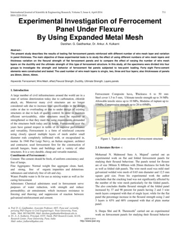
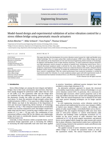
Cooling/HeatingPlate(4 each)Fig. 2 Diagram of the cubical enclosure test cell. Interior dimensionsof the cube are 30.5 cm.MachinedChannels umpCooler/Heater1------o()()----Fig. 3WalerReturn------'Diagram of the cooling/heating circuitstemperature difference, Th - Tc . Therefore, the heated andcooled walls may be considered isothermal.For flow visualization purposes, the top and bottom of theenclosure consists of 1.27-cm-thick lucite plates screwed to thetop surface of the inner plates with a neoprene gasket. The topplate has four compression fittings with rubber septums thatallow hypodermic tubing to be inserted into the test cell.Diluted food coloring is used as the dye and injected throughthe hypodermic tubing into the test cell. The dye is injectedthrough a micrometering valve for flow control at approximately 5 cc per hour flow rate. Total volume of injecteddye for a typical I-hr experiment from all four dye ports istherefore about 0.8 percent of the cell volume. Dye velocity atthe tip of the needle is less than 3 mm/s, which is much lessthan flow velocity in the boundary layers and roughly thesame as the core velocities. When the probe is inserted morethan 10 cm into the cell, heat transfer from the dye, as itflowed through the needle to the test cell, appeared to bringthe dye to thermal equilibrium with the test cell water. Forinsertions of less than 10 cm, the buoyant effect on the dyecould be seen as it exited the tip of the needle. Under theseconditions, the dye drifted upward (or downward in warmregions) for about 1 cm before appearing to move with thelocal flow . When dye was injected into the boundary layer,the probe was adjusted to approach the wall obliquely tocreate minimum flow disturbance, see Fig. 6. Although thismethod of flow visualization is far fro!ll ideal, it does offermany advantages and is very simple to implement.The four aluminum test cell
capability. Average heat transfer coefficients f or the wofls have been measured for several configurations of heating and cooling of 1he verrical isothermal wafls. A unified Nu-Ra correlation has been computed which collapses 1he heOI Irons/er coefficienls of lhe various