Transcription
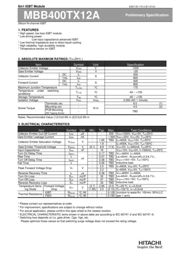
6in1 IGBT ModuleIGBT-SP-17014-R3 (P1/8)MBB400TX12APreliminary SpecificationSilicon N-channel IGBT1. FEATURES* High speed, low loss IGBT module.* Low driving power:Low input capacitance advanced IGBT.* Low thermal impedance due to direct liquid cooling.* High reliability, high durability module.* Temperature sensor on IGBT.2. ABSOLUTE MAXIMUM RATINGS (Tc 25oC )ItemSymbolUnitSpecificationVCESVGESICICMIFIFMTvj maxVVoC1200 20400800400800175Tvj opoC-40 150TstgVISO-oC-40 1252,500 (AC 1 minute)6.04.0Collector Emitter VoltageGate Emitter VoltageDC1msDC1msCollector CurrentForward CurrentMaximum Junction TemperatureTemperature under switchingconditionsStorage TemperatureIsolation VoltageTerminals (M6)Mounting (M5)Screw TorquePCB MountingAAVRMSN·m-(M3 Tapping Screw)(1)(2)TBDNotes: Recommended Value (1)5.5 0.5N·m (2)3.5 0.5N·m3. ELECTRICAL CHARACTERISTICSItemSymbolUnitICESIGES AnACollector Emitter Saturation VoltageVCEsatVGate Emitter Threshold VoltageInput CapacitanceTurn On Delay TimeRise TimeTurn Off Delay TimeFall TimeVGE(th)Ciestd(on)trtd(off)tfVnFPeak Forward Voltage DropVFVReverse Recovery TimeTurn On LossTurn Off LossReverse Recovery LossTemperature Sens- Forward Voltageing DiodeDropIGBTThermal ResistanceFWDtrrEonEoffErr smJ/PmJ/PmJ/PCollector Emitter Cut-Off CurrentGate Emitter Leakage CurrentVFTRth(j-w)Rth(j-w) 60.170.070.380.262.22.20.363247332.852.0-200 .1280.165Test ConditionsVCE 1200V, VGE 0V, Tvj 25oCVGE 20V, VCE 0V, Tvj 25oCIC 400A, VGE 15V, Tvj 25oCIC 400A, VGE 15V, Tvj 150oCVCE 5V, IC 400mA, Tvj 25oCVCE 10V, VGE 0V, f 100kHz, Tvj 25oCVCC 600V, IC 400A,Ls 40nH , RG(on/off) 3.3/4.7Ω,VGE 15V/-15V, Tvj 150oCInductive loadIF 400A, VGE 0V, Tvj 25oCIF 400A, VGE 0V, Tvj 150oCVCC 600V, IC 400A,Ls 40nH , RG(on/off) 3.3/4.7Ω,VGE 15V/-15V, Tvj 150oCInductive loadTC 25 oC, IFT 0.2mATC 150 oC, IFT 0.2mAJunction to water/fin, 10l/min, 50%LLC(per 1 arm)* Please contact our representatives at order.* For improvement, specifications are subject to change without notice.* For actual application, please confirm this spec sheet is the newest revision.* ELECTRICAL CHARACTERISTIC items shown in above table are according to IEC 60747–2 and IEC 60747–9.* Switching loss depends on Ls, gate driver, Cge, Vge, etc.Please optimize those values so that switching surge voltage does not exceed the rating voltage.
6in1 IGBT ModuleMBB400TX12A4. PACKAGE OUTLINE DRAWINGIGBT-SP-17014-R3 (P2/8)Preliminary SpecificationTENTATIVEUnit in mm
6in1 IGBT ModuleMBB400TX12A5. CIRCUIT DIAGRAMIGBT-SP-17014-R3 (P3/8)Preliminary Specification
6in1 IGBT ModuleIGBT-SP-17014-R3 (P4/8)MBB400TX12A6. STATICPreliminary SpecificationCHARACTERISTICSTYPICALVGE 15/14/13/12V800TYPICAL11VVGE 15/14/13/12V800Tvj 25 Tvj 150 Voltage sense:CS* - E* (* : 1 6)Voltage sense:CS* - E* (* : 1 6)60060010V4009V200Collector Current I C (A)Collector Current I C (A)11V10V4009V2008V8V000123450Collector - Emitter Voltage VCE (V)Gate to Emitter Voltage V GE (V)600Forward Current I F (A)Vcc 600VIc 400ATvj 25 104002000Forward Voltage V F (V)Forward Voltage of Free-Wheeling Diode50-5-10Voltage sense:CS* - E* (* : 1 6)4515VGE 0Tvj 25 Tvj 150 34TYPICALTYPICAL23Collector Current vs. Collector - Emitter Voltage80012Collector - Emitter Voltage VCE (V)Collector Current vs. Collector - Emitter Voltage015-15-600-400-2000200400600Gate Charge QG (nC)Gate to Emitter Voltage vs. Gate Charge
6in1 IGBT ModuleIGBT-SP-17014-R3 (P5/8)MBB400TX12A7. DYNAMICCHARACTERISTICSTYPICAL1.2Voltage sense:CS* - E* (* : 1 6)toff1VCC 600VVGE 15/-15VRG(on/off) 3.3/4.7ΩTvj 150 LS 40nHInductive Load0.80.6tf0.4trrton0.2TYPICAL60Switching Loss Eon, Eoff, Err (mJ/pulse)1.4Switching Time t (μs)Preliminary SpecificationEoffVCC 600VVGE 15/-15VRG(on/off) 3.3/4.7ΩTvj 150 LS 40nHInductive Load5040Err30Eon2010Voltage sense:CS* - E* (* : 1 6)tr0001002003004005000100200Collector Current I C (A)1.4Switching300400Collector Current I C (A)Time vs. Collector CurrentSwitching Loss vs. Collector CurrentTYPICALTYPICAL0.8Voltage sense:CS* - E* (* : 1 6)trrSwitching Time t (μs)0.60.5ton0.4tf0.30.2tr0.1VCC 600VVGE 15/-15VI C 400ATvj 150 LS 40nHInductive Load0051015Gate Resistance R G (Ω)VCC 600VVGE 15/-15VI C 400ATvj 150 LS 40nHInductive Load70toff20Switching Loss E on, Eoff, Err (mJ/pulse)0.75006050EonEoff4030Err2010Voltage sense:CS* - E* (* : 1 6)0051015Gate Resistance R G (Ω)0.8Switching Time vs. Gate ResistanceSwitching Loss vs. Gate Resistance20
6in1 IGBT ModuleIGBT-SP-17014-R3 (P6/8)MBB400TX12APreliminary SpecificationTYPICALTYPICAL10001000Voltage sense:CS*-E* (* : 1 6)VCE( Spike voltage)逆回復電流 IR(A)VceB6TV6A-8305600Definition of RBSOA waveformVCC 850VIC 800AVGE 15/-15VRG 4.7ΩCge 0nFTvj 150 Ls 40nHInductive LoadOn pulse width 10us400200Reverse Recovery Current IR(A)Collector Current IC(A)コレクタ電流 IC(A)800Ic(To turn-off)Voltage sense:CS*-E* (* : 1 6)900VCC 850VIF 800ATvj 150 dI/dt 9.2kA/usLs 40nHInductive LoadOn pulse width 10us800700600500400Pmax 180kW3002001000002004006008001000 1200Collector to Emitter Voltage VCE(V)01400Reverse Biased Safety Operating Area2004006008001000 1200Reverse Recovery Voltage VR(V)1400Reverse Recovery Safety Operating Area8. THERMAL CHARACTERISTICSRepresentative ExampleMAXIMUM41Diode0.13.5VFT (V) @IFT 200μATransient Thermal Impeadance Rth(j-w) ( /W)10l/min(LLC50%)IGBT0.010.0010.0013Slope -6.44mV/ 2.521.50.010.11Time t (s)Transient Thermal Impedance Characteristics10-50050100150200Tc ( )On-chip Temperature Sensing Diode Characteristic
6in1 IGBT ModuleMBB400TX12AIGBT-SP-17014-R3 (P7/8)Preliminary Specification9. PRECAUTIONS9-1. Storage and Shipping PrecautionsImportant Notices(1) IGBT modules should always be stored under the following conditions. Temperature:40 degrees Celsius, maximum. Humidity:60% Relative Humidity, maximum. Dust:Avoid storing the module in locations subject to dust. Harmful substances:The installation location should be free of corrosive gases such as sulfurdioxide and chlorine gas. Other:Do not remove the conductive sponges mounted between terminals of gate, emitter,collector, temperature sensing anode.(2) Shipping Method To prevent the case cracking and/or the electrode bending, appropriate consideration should begiven to properly insulate the shipping container from mechanical shock or sever vibration situation. Do not throw or drop the case while shipping. Treat them with care. The devices may break if theyare not handled with care. Please do not use the IGBT modules that were dropped or damaged. Appropriate labeling on the outside of the shipping container should always be present. The shipping container itself should always be properly protected from both rain and water.9-2. Precautions against Electrostatic FailureImportant NoticesBecause the IGBT has a MOS gate structure and temperature sensing diode, you should always take thefollowing precautions as measures to avoid generating static electricity. Before starting operation, do not remove the conductive sponge mounted between terminals of gate,emitter, collector, temperature sensing anode. When handling the IGBT module, ground our body via a high-value resistor (between 100kΩ and1MΩ), hold the package body, and do not touch the terminals of gate, temperature sensing anodeand cathode. Be sure to ground any parts which the IGBT module may touch, such as the work table or solderingiron. Before testing or inspection, be sure to check that any residual electric charge in measuringinstruments has been removed. Apply voltage to each terminal starting at 0V and return to 0V whenfinishing.
6in1 IGBT ModuleIGBT-SP-17014-R3 (P8/8)MBB400TX12APreliminary SpecificationHITACHI POWER SEMICONDUCTORSNotices1. The information given herein, including the specifications and dimensions, is subject tochange without prior notice to improve product characteristics. Before ordering,purchasers are advised to contact Hitachi sales department for the latest version of thisdata sheets.2. Please be sure to read "Precautions for Safe Use and Notices" in the individual brochurebefore use.3. In cases where extremely high reliability is required (such as use in nuclear powercontrol, aerospace and aviation, traffic equipment, life-support-related medicalequipment, fuel control equipment and various kinds of safety equipment), safety shouldbe ensured by using semiconductor devices that feature assured safety or by means ofusers’ fail-safe precautions or other arrangement. Or consult Hitachi’s sales departmentstaff.4. In no event shall Hitachi be liable for any damages that may result from an accident orany other cause during operation of the user’s units according to this data sheets. Hitachiassumes no responsibility for any intellectual property claims or any other problems thatmay result from applications of information, products or circuits described in this datasheets.5. In no event shall Hitachi be liable for any failure in a semiconductor device or anysecondary damage resulting from use at a value exceeding the absolute maximum rating.6. No license is granted by this data sheets under any patents or other rights of any thirdparty or Hitachi Power Semiconductor Device, Ltd.7. This data sheets may not be reproduced or duplicated, in any form, in whole or in part,without the expressed written permission of Hitachi Power Semiconductor Device, Ltd.8. The products (technologies) described in this data sheets are not to be provided to anyparty whose purpose in their application will hinder maintenance of international peaceand safety not are they to be applied to that purpose by their direct purchasers or anythird party. When exporting these products (technologies), the necessary procedures areto be taken in accordance with related laws and regulations. For inquiries relating to the products, please contact nearest overseas representatives that is located“Inquiry” portion on the top page of a home page.Hitachi power semiconductor home page address p/en/
* Low driving power: . - 2.2 - I F 400A, V GE 0V, T vj 150oC Reverse Recovery Time t rr s - 0.36 TBD V CC 600V, I C 400A, Ls 40nH , R G V GE . The devices may break if they are not handled with care. Please do not use the IGBT modules that were dropped or damaged.