Transcription
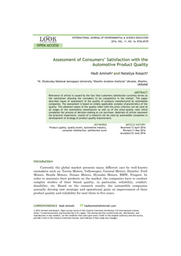
[L@ @lMil@1FU SPECIFICATIONSGENERAL MOTORSMODEL GP38-22000 HP DIESEL-ELECTRICGENERAL PURPOSE LOCOMOTIVEElectro-Motive DivisionLa Grange, IllinoisSpecification 8090January 3, 1972Revised July, 1975GM'-------.I
INDEXGMSECTIONGENERAL INFORMATIOI\JAND IDENTIFICATION1CARBODY CONSTRUCTION .2TRUCKS. .3POWER PLANT AND TRANSMISSIONENGINE, GENERATOR, COOLING AI\JD. .LUBRICATING SYSTEMS4AIR BRAKES5EQUIPMENT6LOCOMOTIVE MODIFICATIONS. . . . . . . . . . . . . . . .7PAINTING.8PERFORMANCE DATA. . .9SPECI FICATION AMENDMENT . . . . . . . . . . . . . . . . .10CLEARANCE DIAGRAM .11CAB ARRANGEMENT .12TRACTIVE EFFORT13GENERAL OUTLINE14
SECTION 1GENERAL INFORMATIONAND IDENTIFICATIONMODELTYPEARRANGEMENTGMGP38-2 2000 HP Diesel-Electric General Purpose Locomotive.AAR Designation (B-B), Common designation (0440).The general arrangement of the locomotive is shown on Elevation and FloorPlan Drawing attached.The locomotive consists of one unit complete with engine, generator, trucksand all necessary accessories for single unit operation, with a control cabbetween the long and short hoods.NOMINALDIMENSIONSDistance, pulling face of coupler tocenterline of truck . 12' 7"Distance between bolster centers . , . , . , . , . 34' 0"Truck - rigid wheel base. ' . , . , . , . , . , . , . 9' 0"Distance, pulling face front coupler to rear coupler . 59' 2"Width over cab sheeti ng . , . , . 10' 0"Width over handrail supports . , . 10' 3-1/8"Height, top of rail to top of cooling fan guard . 15' 4-7/16"Width over basic arm rests . , . 10' 4"DRIVEDriving motors . , . , . FourDriving wheels . 4 PairDiameter wheels . 40"WEIGHTSAND SUPPLIESTotal loaded weight on rails (approximately) . 250,000Ibs.Fuel . . . , . 1,700 gal.Sand . 56 cu. ft.Cooling water. . . . . . . . . . . . . . . . . . . . . . . . . . . . . . . . . . . . . . . . . 240 gal.Lubricating oil. . . . . . . . . . . . . . . . . . . . . . . . . . 243 gal.CLEARANCESLocomotive outline drawing found in rear of specification book Illustratesclearance conditions.SAFETYAPPLIANCESAll steps, grab handles and other safety appliances cover EMD interpretationof I nterstate Commerce Commission requirements.
1General Information And IdentificationSECTIONCURVENEGOTIATIONGMTruck swing limits single unit curve negotiation to a 42 or 140 ft. radiuscurve.Single unit coupled to a 50 ft. car is limited by car coupler swing to a 19 or 302 ft. radius curve.Two units coupled in multiple limited by coupler swing to a 30 or 190 ftradius curve.8090 Rev. 2/17/75
C)SECTION 2CARBODYCONSTRUCTION -------I[ GM [FRAMINGUnderframe is of constant section design and serves as main carrying memberfor hoods, cab and equipment. Two channel side sills supported by centersills support catwalk along side of hoods. Draft gear pockets are welded tothe built-up platform construction between center sills. The structure isall welded construction.COLLISIONPOSTSCollision posts are designed integrally with low front hood and welded tounderframe.FLOORINGFloor plates with antiskid surface are welded to underframe on end plat forms and along side of hoods. Plywood cab floor covered with linoleum.UNDERFRAMECENTERBEARINGSWelded to body bolster assembly.COUPLERSType "E", 6-1/4" x 8" shank, 28-112" long. Maximum operational swingof coupler is 17 0 to either side of centerline. Maximum free (manual)swing is 4 0 from center.UNCOUPLINGDEVICEEach end of the locomotive is provided with a top operating device arrangedto operate from either side of the locomotive.DRAFT GEARNational Castings NC-391 rubber draft gear with alignment control.JACKING PADSPLATFORM STEPCAB8090 Rev. 2/17/75Combination jacking pad and cable sling is provided nearside sill.bolster atSteps are provided at each corner leading to locomotive platform.The floor is elevated above the top of the underframe. A trap door in cabfloor and side drop doors provide access to equipment beneath cab floor.Doors are located at diagonally opposite corners leading to platform along side hoods. Side windows on both sides of cab are sliding double sash typeand fitted with latches. End windows in doors and cabstationary andset in a special rubber retainer. Cab is of fabricatedconstruction.Divided center window is provided over low short hood.
2Car body ConstructionSECTIONWINDOWS8MAll windows and doors are provided with safety plate glass.DOOR LOCKSThe cab doors are fitted with an inside latch and provided with a lock.Doors are of honeycomb construction.INSULATIONCeiling is lined with perforated metal for sound reduction; backed up byinsulation. Acoustic and thermal type insulation is added to the cab sidewalls and the rear partition of the electrical cabinet.BATTERY BOXTwo battery boxes are provided. one on each side of the short hood. Trapdoors in catwalk provided for servicing and bolted removable panelsprovided for removing batteries. Ventilation and drainage provided. Batteryboxes are sized to fit either 17 or 25 plate batteries.HOODThe power plant compartment is designed to a minimum width to providea walkway around the hood. Doors are provided which give access to powerplant equipment and allow removal of complete power assemblies. Hatchessupporting cooling fans can be removed separately for removal of radiators.The hood is bolted to the inertial filter compartment and to the deck andcan be removed complete with radiators and cooling fans for major repairs.When provided. dynamic brake hatch can be removed separately.HOOD DOORSAll side doors have suitable outside hinges and latches.LIFTING EYESProvision is made for lifting eyes on hood and hatches to facilitate handlingwith a crane.BALLASTThe locomotive is basically designed for balance.,
SECTION 3TRUCKSTRUCKASSEMBLIESGMTwo four-wheel truck assemblies are provided per locomotive and areinterchangeable.Fully flexible bolster supported on springs providing vertical movement;swing hangers provide lateral movement. The truck frame is supported oneach of the four journal boxes by twin coil springs.Each of the four motors is supported by the driving axle to which it isgeared, and a special suspension on the truck transom provides a flexiblesupport, dampening the torque shocks of the motor.AXLESAxles with journals to suit Hyatt roller bearings. Axle material conformsto physical properties of current AAR specifications.WHEELSRolled or cast steel, heat treated, rim quenched, 40" diameter with 2-1/2"rim. Wheel treads are finished smooth and concentric. AAR diameterindex groove is provided to indicate wheel wear.JOURNALBOXESLocomotive equipped with Hyatt roller bearings 6-1/2" journals of specialEMD design. I mproved rear cover seal and oil fill cup for improved oilretention and inspection provided. Crowned rollers extend bearing life.Lateral thrust is taken through a cushioning arrangement directly by thebox with improved oil flow over thrust block characteristics. Journal boxpedestal guides provided with spring steel wear plates.PEDESTALSPEDESTALTIE BARSLined with composition nylon plates bolted to frame.Fitted and applied at the lower end of the pedestal legs, held in positionby bolts.TRUCK CENTERBEARINGRECEPTACLETruck center bearing receptacle provided with wear plates and dust guard.SIDE BEARINGSFriction type side bearings.INTERLOCKSBody and truck interlocks provided each side of the center plate, servingas antisluing device in case of derailment.
c)SECTION3TrucksTRUCK BRAKESGMClasp brake rigging provided on each wheel, operated by individual brakecylinders.SLACKADJUSTERSPin type slack adjusters.BRAKE PINSAll pins and bushings hardened and ground.HAND BRAKE( )8090 Rev. July, 1975Hand brake provided for the locomotive connected to one brake cylinderlever only. All trucks provided with lever for hand brake connection,making trucks interchangeable.
SECTION 4POWER PLANTAND TRANSMISSION----:---:--:--------.J! GMENGINEGeneral Motors sixteen cylinder, 2 cycle diesel engine. Power assemblarranged in 45 degree V, with 9-1/16" bore, 10" stroke, and unit injection.Roots blower scavenging through cylinder wall intake, and multivalve ex haust. Water cooled cylinder liners and heads, oil cooled pistons, ten bearingcrankshaft, drop forged connecting rods, and floating piston assembly.Isochronous governor speed control, separate overspeed trip and high crank case pressure protection. Engine shipped without lubricating oil.MAINGENERATOREMD AC main generator with rectified output for delivery to tractionmotors, 600 volt (nominal) direct current rating, ventilated by blower.Armature shaft supported by single bearing with direct connection toengine crankshaft through alternator rotor and flexible coupling. Adequatecapacity to continuously transmit the rated output of the engine under allconditions for which the locomotive is designed.GENERATOREXCITATIONExcitation for main generator supplied from the alternator through siliconcontrolled rectifiers.ALTERNATOREMD 200 volt, 3-phase, 16 pole alternator, built integral with main generator,to supply AC power to induction motors driving engine cooling fans.LOCOMOTIVECONTROLPermanent parallel connection with no motor field shunting or fully auto matic transition with no motor field shunting, dependent upon selection ofgear ratio. High voltage circuits safeguarded by ground protective relay. Fullrange wheel slip control with automatic sanding under wheel slip conditions.LOAD CONTROLLoad control provided to automatically maintain horsepower output in accord ance with the published tractive effort characteristics of the locomotive.TRACTIONMOTORSFour EMD direct current, series wound, forced ventilated, axle hung motorswith high capacity roller type armature bearings, new bearing seals, Tefloncovered string bands and improved pinion gear contour are all provided.AUXILIARYGENERATORDirect current generator, driven from engine gear train, provides current forcontrol circuits, lighting, battery charging, and separate excitation of maingenerator. Voltage automatically controlled by static voltage regulator.ENGINESTARTINGSTORAGEBATTERYRev. 1/74Engine is started by using twofrom the locomotive batteries.engine.volt series connected motors, energizedne start switch at governor end of32 cell, 64 volt, 420 ampere hour capacity (8 hour rating) battery housedto short hood.in two boxes located under catwalks
4Power Plant And TransmissionSECTIONGMENGINECOOLINGPressurized cooling system consisting of direct driven centrifugal water pumpon the engine, radiators, and AC motor driven cooling fans located aboveradiators at rear of long hood. Water cooled oil cooler and water tankmounted as a unit directly in rear of the governor end of engine, automaticwater temperature control, hot engine alarm, and engine shutdown in theevent of low water level, are included. Improved water fill system toprevent inadvertent opening of the pressure cap is provided. Water levelinspection window in hood is provided.ENGINELUBRICATIONThe engine lubricating oil system is a pressure system using two positivedisplacement gear type pumps combined in a single unit. One pump deliversoil for the pressure lubricating system, the other for piston cooling. The oilsupply to these pumps is drawn from the oil strainer chamber through acommon suction pipe.A scavenging oil pump is used to draw oil from the engine oil pan through astrainer, pump it through the full flow lube oil filter to the. cooler coresection of the cooler tank and return it to the strainer chamber. Low oilpressure and high oil temperature protection is provided resulting in engineshutdown.ENGINE AIRINTAKE FILTERSPaper filters provided for engine intake air.ENGINE EXHAUSTTwo sets of dual fabricated chambers, each set with an independent exhaust.ENGINEFUEL SYSTEMReturn flow. single DC motor driven gear pump, protected by suctionstrainer, and discharge filters with filter by-pass and indicator to insureclean fuel for the engine. Sight glasses permit visual inspection of fuel flow,and relief valve offers protection against excessive pressures.FUEL TANK1700 gallon capacity, fuel tank built of heavy gauge steel. with baffleplates, located underneath the locomotive body. One filling station oneach side. Tank equipped with venting, cleanout plug. and nonremovablewater drain.One dial type fuel gauge on right side of tank and one direct reading typefill sight glass on each side of tank. Each filling station provided withelectric emergency fuel cutoff actuating button.Similar pushbuttonlocated in cab. When operated, engine stops immediately.ENGINEER'SCONTROLSTATIONControl station, located conveniently to the left of the engineer's seat,includes the engine speed throttle, locomotive reverse lever, automatic andindependent brake valve. The lever arrangement is such that the throttlemust be in idle before the reverse lever can be removed to isolate the con troller. The horn valve, bell valve and independent sander switch are alsolocated in the control stand.8090 Rev. July, 1975------------.----------------------------,., ------- .
4Power Plant And rol and lighting switches located within reach of the en(lineer, includingswitches for control and fuel pump, generator field, engine run, gauge lights,headlight "bright" front and rear, headlight "dim" front and rear. Enginestop, number and class light and isolation switches located on rear cab wall.Cab heater switches are located on cab heaters, providing individual control.ENGINEER'SINSTRUMENTPANELA lighted instrument panel is provided on top of the engineer's controllercontaining 4-1/2" air brake gauges, wheel slip light, ground relay light, PCS"open" light, and the traction motor load indicating ammeter.SPEED RECORDERA combination instrument containing the speed indicating dial, speed record er, tape, and mileage odometer is provided on the front cab wall.EQUIPMENTAIR SUPPLYAn inertial separator, roof mounted in a separate compartment behind thecab, supplies filtered intake air to major components. The sepa ated con taminants are blown out by an AC fan incorporated in the separator. Filteredair is supplied to the combination traction motor and main generator blowerand the engine air filters. Traction motor air is delivered to a duct andplenum chamber system on the underframe and supplies the traction motorswith cQoling air. The main supply air duct forms the left side walkway.Generator discharge air is used to pressurize the engine compartment.Electrical cabinet is ventilated through four element filter using standardpleated paper lube 011 filters from the blower air supply.ELECTRICALCONTROLCABINETA totally enclosed, readily accessible, cabinet houses the locomotive highand low voltage control equipment. Fault annunciator panel is providedwithin the cabinet to indicate equipment malfunctions.An additional cabinet, mounted in the engine room, houses the controlequipment for the radiator cooling fan motors. Fuse panel is provided forcooling fan protection.Control equipment includes a full complement of control circuit plug-inmodules, high capacity power contactors, and gang operated reverser andtransfer switches.
1(···· \--)SECTION 5AIR BRAKESAIR BRAKESFOUNDATIONBRAKES8M26L brake schedule including self-lapping independent and standard 26Fcontrol valve portions.9" x 8" cylinders, 5.65: 1 lever ratio, 14" cast iron brake shoes.BRAKE PIPINGWrought steel pipe with AAR fittings are used. Generally, all piping 1/2"0.0. and under uses nominal size steel tubing with SAE fittings.MAli\! RESERVOIRTwo 15" diameter x 152" steel reservoirs mounted beneath the underframe.Total capacity: 49,000 cu. in. No.1 main reservoir equipped with an airoperated automatic drain valve.AIRCOMPRESSOROne two stage, three cylinder, water cooled direct coupled compressor,having a displacement of 254 cu. ft. per minute at 900 RPM. Compressoris equipped with large oil capacity and disposable intake air filter.Electric air compressor governor adjusted to maintain reservoir pressurebetween 130 and 140 psi.SANDCAPACITYTwo sand boxes with a total capacity of 56 cu. ft.Sand boxes are filled from the outside of locomotive on top of hoods.SANDINGSanding systems are controlled electrically. Manual sanding switch or auto matic sanding in power operates eight single line sand traps, four traps forforward movement and four traps for reverse movement. A separate switchis provided for lead axle sanding only. Sandtrap cutoff valves are provided.Outside access is provided for trap maintenance.CONDUCTOR'SBRAKE VALVEConductor's brake valve is provided on the left side of the cab.GAUGES ANDTEST FITTINGSLarge 4-1/2" air gauges fitted with gauge test fittings are standard.fitting also supplied at compressor un loader switch.C)8090 Rev. 1/2/75Test
SECTION 6EQUIPMENTCAB HEATINGANDVENTILATINGWINDOWWIPERSSUN VISORSCAB SEATSFIREEXTINGUISHERSGMTwo combination hot water cab heaters and defrosters with fan driven aircirculating system, and selective outside air intake. Each heater is providedwith three speed switch for control of fan speed.Total of six air operated window wipers are provided for front and rearwindows on both sides of cab and center windshields.Total of four adjustable metal sun visors are provided.The two wall mounted upholstered cab seats have forward and backward aswell as height adjustments. Both seats can be turned 180 degrees. Armrests are provided outside the side windows.Two 20 lb. Ansul, one located in cab, the other in the engine compartment.HEADLIGHTTwin sealed-beam headlights, front and rear, are equipped with two 200watt, 30 volt sealed beam units. Bright and dimmer switch for each lightprovided in operator's cab.WARNINGDEVICESThree chime diaphragm type air horn, two bells pointing forward and oneto the rear with lever operated modulating horn valve. Horn is located oncenter line of cab roof.One 12" locomotive bell with internal pneumatic ringer, located inunderframe.LOCOMOTIVELIGHTING()Lights and outlets are as follows:1.2.3.4.5.6.7.8.9.Two ceiling cab lightsTwo engine room lightsTwo ground lightsEight number lightsThree gauge lightsOutlet receptacles: one in engine room, one in cabOne short hood compartment lightFour classification lightsTwo platform lights, one each end
(-Ij()6EquipmentSECTIONGMMARKER ANDFLAG BRACKETSFour standard combination flag and light brackets are prcvided, two eachare located at front and rear of locomotive.NUMBER BOXESFour lighted number boxes, two on each end of locomotiv'3, mounted at anangle for both forward and side visibility. Numbers are painted on glasswindows and are not removable.CLASSIFICATIONLIGHTSClassification lights built into each corner of front and rear hood.MISCELLANEOUSTwo coat hooks provided in cab.
c)SECTION 7LOCOMOTIVEMODIFICATIONS.'---- ----------------------------------------- GMThe following modifications can be supplied on request to satisfy variousoperating requirements. The base price of the locomotive d3scribed in thisspecification does not include these modifications.MULTIPLECONTROLMultiple control equipment available to allow operating twc or more unitsfrom one cab. Locomotive equipped with one 27 point power plant recep·tacle per end and one power plant jumper cable is provided.AIRCOMPRESSORTwo stage, six cylinder air compressor, water cooled, having a displacementof 401 cu. ft. per rriinute at 900 RPM.WATER COOLERTOILETFUEL TANKToilet of incinerating, chemical, flush type with water tank, or dry hoppertype is available.3600 gallon fuel tank is available.CAB SEATThird cab seat. slide rail mounted is available.SAND BOXCAPACITYSand boxes can be provided with a total capacity of 36 cu. ft. per end.TRACTIONMOTOR ACCESSCOVERSSPARK ARRESTORMANIFOLDS(JWater cooler or refrigerator cooler with cup dispenser is availa:: le.Quick access bottom traction motor covers are available as a modification.Retention trap type spark arrestor manifolds are avai lable.JACKING PADSCombination jacking pad and cable sling can be provided at four cornersbehind step wells.DEEP SUMPOIL PANEngine usable oil capacity increased 137 gallons and total cap3city increased153 gallons.SIDE FOOTBOARDSSide foot boards at each corner of locomotive, meeting Federal RailroadAdministration requirements for locomotives used in switching service, areavailable.8090 Rev. July, 1975
C)7Locomotive ModificationsSECTIONSINGLE SHOEBRAKE TRUCKASSEMBLIESGMInterchangeable, four wheel, single shoe braketruckassemtliesareavailableas a modification.Stra ight across bolster is supported at each end by rubb3r spri ng pads onthe frame. The truck frame is supported at each of the four journals bystandard twin coil journal springs. Two hydraulic dampers are locatedbetween frame and journal box, at diagonally opposite corners, to insurevertical stability. Swing hangers are shorter and safety straps redesignedcompared to the clasp brake truck. Each of the four motors is supportedby the driven axle to which it is geared. Special nose support on the trucktransom provides flexible support to dampen motor torque shocks.16" composition brake shoes, on SO type brake heads, are utilized onsingle shoe brake rigging which utilizes same cylinder levers, brackets andair cylinder mounting as used on GP clasp brake trucks. O:her brake leversare designed especially for this single shoe truck. Two brake cylinders(9" x 8"), diagonally located and frame mounted are providEid.()Hand brake application is same as for the clasp brake truck.DYNAMICBRAKESVariable dynamic brakes use the traction motors as gene'ators, with thepower being dissipated through force ventilated grid resisto's located in theengine hatch. Variable voltage type control is standard with :Jynamic brakes.Positive indication of "power" or "dynamic brake" mode of operation isclearly shown at controller.Extended range dynamic braking providing high brake effort at low speed isalso available. Parallel grid connection to improve wheel sl ide protectionis provided. 4-112" zero-center ammeter contains both "brake" and "power"indication, reading in opposite directions from center for each function.Enforced time delay from "power" to "brake" is standard.A grid current trainline control feature is available, if desirec.Grid blower protection is available preventing dynamic bnke operation asresult of stalled blower motor or no motor current.SELF LOAD TESTA self load test feature permitting locomotive loading on its own dynamicbrake grids is available.
SECTION 8PAINTINGOUTSIDE FINISHENGINE ROOMUNDER CARRIAGECABTRUCKS & TANKS()GMColor arrangement and design to agree with railroad's requirenent.Inside finished in suede gray. All air, fuel, water and lube cil piping colorcoded at points of connection.Black unless otherwise specified.Inside finished in suede gray.Black unless otherwise specified.
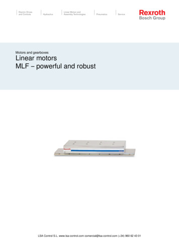
SECTION 9PERFORMANCEDATAOPTIONALGEAR RATIOSGMThe choice of gear combinations will depend upon the servicE contemplatedGEAR RATIO62:1561: 1660:17MAX. SPEED657076, , , MINIMUMCONTINUOUSSPEED (MPH)10.911.612.5. HORSEPOWERRATINGThe GP38-2 locomotive develops 2000 nominal horsepower into the gen erator for traction at 900 RPM of the engine under the following conditions:60 0 F air intake temperature29.9 inches hg barometer (minimum)0.845 specific gravity fuel.83 engine governor rack setting60 0 F fuel temperature()
SPECIFICATION AMENDMENTGMElectro-Motive Division Locomotive Specification No. 8090 is amended to incorporatecertain Remanufactured components.The items listed below constitute the maximum number of Remanufactured componentsthat may be incorporated in the GP38-2 replacement locomotive.ENGINE PARTSCrankshaftCamshaftsCam blocksHarmonic balancerLube oil scavenging pumpPiston cooling and pressure pumpAccessory drive housingEngine blowersWater pumpsFuel pumpCamshaft drive housingAUXILIARY GENERATOR014 ALTERNATORTRACTION MOTOR PARTSFrame assembly and pole piecesArmature core, commutator,and armature shaftBearing housing and assembly partsTRUCK ASSEMBLY PARTSAxles and axle gearsFrame, bolster, spring plank, safety straps,side bearing clips, and pedestal tie barsCoil and elliptic springs and coil spring seatsBrake cylindersBrake levers, straps, and slack adjustersRoller bearing journal box assembliesSPEED RECORDER AND RIGHT ANGLE DRIVESpecification Amendment No. 8090-3January 3, 1972Electro Motive DivisionGeneral Motors CorporationLa Grarlge, Illinois
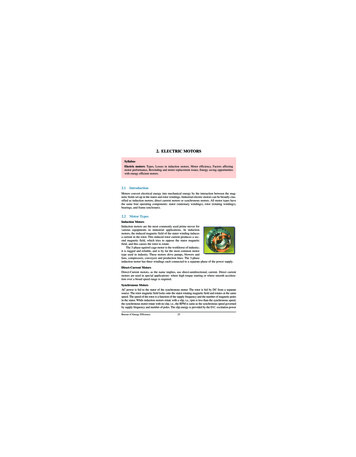
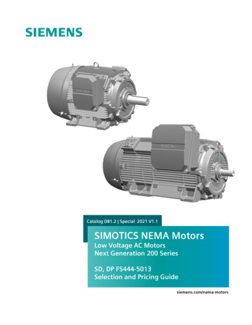
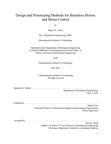
GP38-2 CLEARANCE DIAGRAM5(-)173z234IiiIr - -- f-----Ilon, 4 IN, OVERFLAG BRACKETS I-- - ----I----.i-174 II1rl--- --"-' - --- IOFT'2i'N'OVER GUTTERS - ---j - --. ·.·-.J- -"""'n16II:)151413131212. -/---II1010II9(;/II9HANDRAIL SUPPORTS ----- -- I9 )- --- --H-- --. -- ------4L-.-- --- ---- ---- -- - - - - - - - 1 - 1 1 - . -;.-. 10 FT . 0 II7!---. - - IOFT., I .OVER C A l - - I - - - - - - - - - - - - IIT7IIf'I' OVER9HANDRAIL'S --- ---l----l--- 6i55II443PADS2I10FT·O IN. OVERIFUELITANK 1/-I--------fI9FT. SlIN, OVER ST"P,L.SUPPORT '/1/-'I"0. TOP5OF RAILLOCOMOTIVE IS SHOWN INCLUDING HALF VARIABLE SUPPLIES ANI) INNOTE:NEW CONDITION, STANDING STILL ON LEVEL AND TANGENT TRA( K,LOCO. HEIGHT TOLERANCE :tI Y,LOCO. WIDTH TOLERANCE::: t ItzVERTICAL DIMENSIONS WILL BE IV2'" LESS WITH FULL WHEEL "EAR.VERTICAL DIMENSIONS CAN ALSO VARY t 8 DUE TO VARIABLE SJPPLIES.TRUCK LATERAL AT BOLSTERS Z Y4 NOM.CLEARANCE OUTLINE lAA.R. PLATE'S' DATED MARCH 1,1969 - - - - A.A.R, PLATE 'C' DATED MARCH 1,19G9 - - - - - APRIL. 1972
CAB ARRANGEMENTie------8@ ---- tIHi 1----\ ID-----G 1234MAY 1972EngineersControl Stand 6A Upper DoorsEngineers Seat6B Middle DoorSeat Stop-Permanent6C Lower DoorsAuxiliary Seat7 Trap Doorw/Adjustable Stop8 Cab Heater Hot Water (2)5 Cab Door (2)6 Electrical Cabinet9 Emergency Brake Valve10 Fire Extinguisher-20 Lb.11 Arm Rest (2)12 Fusee Rack13 Sun Visor (4)14 Window Wiper (6)15 Speed Recorder161718192021Defroster DuctDoor StopShort Hood DoorStep-Down to Short HoodGrab Iron (2)Battery Box (2)2223and BoxBox Extra Capacity24 L.amp Bracket25 Hand Brake Recess26 (:oat Hook (2) and
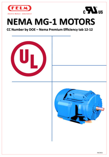
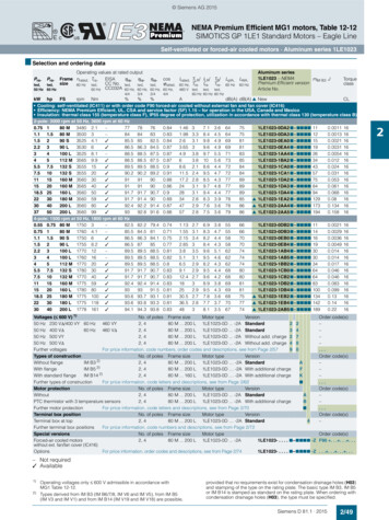
COMPARATIVE SPEED TRACTIVE EFFORT CURVE2000 HP Model GP38-2 Locomotive80,000Equipment:en"0C::J11460,00016 645EEngineAA 10 Generator fJ77T'facti()n Motors40" Diameter Wheelso0.0',i:iI ('0a:a::: LL.40,000«I1.0.Nt.O(0r--co.,.0(0(00 LO(0NQ)(!)WW ci.l CJ)t)«a:::I X('02!20,000oo1020304050SPEED -601.0(0or--70r--co9080Miles Per HourLO.!:::. N a:o co ',l'--./ - '\t}\ /\'0
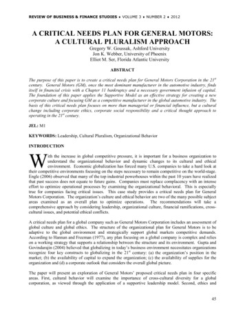
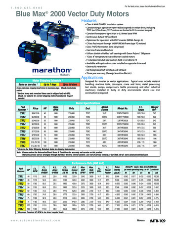
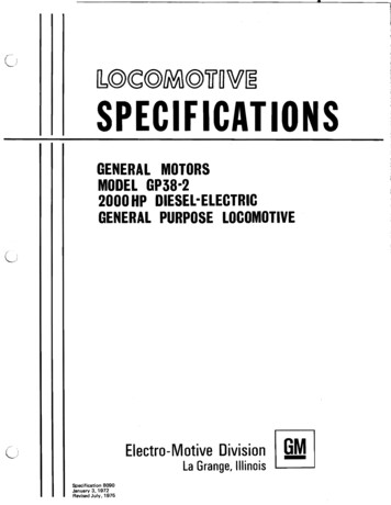
MODEL GP38-2CJ2000 HP GENERAL PURPOSE LOCOMOTIVE1. ENGINE 16·645E19. BATTERIES20. FUEL TANK (1700 GAL. SHOWN)2. GENERATOR·ALTERNATOR AR10E1·D143. TRACTION MOTOR ·GENERATOR BLOWER 21. MAIN AIR RESERVOIRS4. AUXILIARY GENERATOR22. COOLING AIR INLET SHUTTERS5. ELECTRICAL CONTROL CABINET23. LUBE OIL FILTER* 6. AIR COMPRESSOR (WBG SHOWN)24. ENGINE AIR FILTER7. ENGINE EXHAUST STACK.25. INERTIAL AIR SEPARATORNOTE:8. HANDBRAKE26. NUMBER BOXLOCOMOTIVE HEIGHT TOLERA \ICE 1% IN.9. SAND BOX FILLER27. TRACTION MOTOR AIR DUCTLOCOMOTIVE WIDTH TOLERAI\CE 1/2 IN.10. LUBE OIL COOLER28. BELLTRUCK LATERAL AT BOLSTERl: 114 IN. NOM.11. ENGINE WATER TANK*29. DYNAMIC BRAKE FAN12. 48 INCH COOLING FAN30. PILOTLocomotive is shown including half variable supplies and13. RADIATOR31. COUPLERin new condition standing still on Ie lei and tangent track.14. HORN32. FUEL FILTER15. EXHAUST MANIFOLD33. TRUCK· 4 WHEEL16. SAND BOX34. ELECTRICAL CABINET AIR FILTER*17. FUEL FILLER18. HEADLIGHT*MODIFICATION CAB BOLSTERHOOI. BOLSTERICjElectroMotive DivisionJULY 1975La Grange. IllinoisIWilI
General Motors sixteen cylinder, 2 cycle diesel engine. Power assembl arranged in 45 degree V, with 9-1/16" bore, 10" stroke, and unit injection. Roots blower scavenging through cylinder wall intake, and multivalve ex haust. Water cooled cylinder liners and heads, oil cooled pistons, ten bearing