Transcription
ADOT TRAFFIC DESIGNCADD STANDARDSOctober 2019
CHAPTER 1INTRODUCTION3CHAPTER 2LEVELS5CHAPTER 3CELLS6CHAPTER 4LINE STYLES7CHAPTER 5CADD FILE NAMING8CHAPTER 6REFERENCE FILES10CHAPTER 7PRINTING AND PLOTTING12CHAPTER 8SET UP FOR TYPICAL PLAN SHEETS14CHAPTER 9RECORD DRAWINGS17CHAPTER 10TOOLS18CHAPTER 11MICROSTATION INTERFACE CUSTOMIZATION21APPENDIX 1TRAFFIC DESIGN DRAFTING GUIDE EXAMPLE SHEETSAPPENDIX 2ADOT LEVEL STRUCTUREAPPENDIX 3SECTION 409 OF THE DICTIONARY OF STANDARDIZED TASKSAPPENDIX 4ADOT APPROVED LINE STYLES2
CHAPTER 1INTRODUCTIONThe purpose of this manual is to establish uniform policies and procedures to ensure compliance with the TrafficDesign Group’s Computer Aided Design and Drafting (CADD) standards, to produce a plan set that is consistent inappearance, and to ensure quality.This manual is intended to be used as a quick reference guide. Chapters are broken out by subject and sheettype. For more information regarding the Traffic Design Group’s CADD Standards, visit the web site.Drafting Standards for other Groups within ADOT can be found at their respective web sites and are notduplicated in this manual.Although this manual contains information on MicroStation tools and functions, its intent is not to teachMicroStation, but to convey to the user established ADOT Traffic Design CADD Standards.PLEASE NOTE:DRAFTING STANDARDS ARE ESSENTIAL IN PRODUCING A READABLE, CONSISTANT, QUALITY DOCUMENT. YOURATTENTION TO, AND USE OF THESE STANDARDS ARE IMPORTANT!3
SOME HELPFUL DRAFTING TIPS:1. Text conflicts are not acceptable,ever.2. Spelling – Use Spellcheck - incorrectspelling and bad grammar are notacceptable.3. Do not highlight a redline as beingcompleted unless it is 100%complete. Highlighting incompletework is unacceptable.4. All text is to be read from thebottom and/or the right hand side –No exceptions.5. No upside down text.6. Text – same style/height/weight onevery sheet – no exceptions.7. Lines – same type/weight everysheet.8. Leaders/Arrows – Radial,Perpendicular, Trimmed.Not Acceptable9. Check to make sure that thecallouts/information on the planmakes sense – if 3 is for a firehydrant, make sure it doesn’t pointto a valve. If you change inverts ona pipe you will have to revise theslope, etc.10. Each time you run a plot it cannotlook different (screening, etc.).11. Use the correct levels/colors foreverything.12. Redlines are bad – the less red thebetter. Any more than one redlineto get something done is inefficient.13. If you are not sure – ASK!14. Efficiency/Production are the goals.15. Three Golden Rules:a. Check your workb. Check your workc. Check your work16. The final product must be clear andcorrect – it’s your job to ensure this.4
CHAPTER 2LEVELSThe ADOT Traffic Group uses the levels structure as defined in the ADOT Level Structure. Numerical values areused to designate the level names. Levels 1-63, (not Level 1, Level 2, etc.) or the original levels. Over the pastfew years additional level names have been added and incorporated, ADOT Traffic Design Group does not useany of the new levels, except level 295 which is a no-plot level. Level numbers and level names are the sameallowing for key-ins “LV 1”, etc.NO FILES SHALL BE DEEMED ACCEPTABLE THAT CONTAIN ANY OTHER LEVELS OTHER THAN THOSE DEFINED INTHE ADOT LEVEL STRUCTURESee Appendix 2, ADOT Level Structure.5
CHAPTER 3CELLSIn the spring of 2014, ADOT Traffic Engineering updated some of their cell libraries. New sign libraries have beencreated to reflect the changes in the MOAS and ADOT Traffic Standards (see below). The new sign cells have beencreated so that they will all be proportional when placed at the same Active Scale.Traffic V8.cel has been updated and renamed to Traffic V8i. Portions of the original cell library have been removedand placed into new libraries, Accident.cel & Pave Patt.cel.TSL V8i includes updated cells for signal and lighting applications.The following are the ONLY approved CADD cell libraries for Traffic Design. These libraries should contain most ofthe cells required to complete a pavement marking, signing, lighting and traffic control plan.V:\Standards\English\ADOT.cel.ADOT.cel (and other ADOT cell libraries).V:\Traffic\Dev V8i\Celllibs\traffic V8i.cel.Cells used in the preparation of Pavement Marking, Signing and TrafficControl plans.V:\Traffic\Dev V8i\Celllibs\Sign 2014-X.Libraries containing signs from the Manual of Approved signs(sign04.cel may be used as needed).V:\Traffic\Dev V8i\Celllibs\tsl V8i.cel .Cells used in preparation of Signal and Lightingplans. All of the above cellsmay also be found on ADOT Traffic Engineering’s web -construction/traffic/cadd-standardsSIGN CELLSSigns contained within the new Sign 2014 X series of libraries were all created at 1” 1’. If a sign is 24” x 24” inreality, when placed into a sheet at an active scale of 1, the sign will measure 24’ x 24’. If all signs are placed usingthe same scale factor, the signs will be proportional to one another.Once a scale factor is decided upon, all sheets in the project should use that scale for sign cells. TIPS WHILE o WORKING WITH CELLSDo not drop cells to edit the text, the word processor style text editor has the capability to edit text within cells.Do not use shared cells, unless a need truly exists.Users may create a library of their own to house custom cells.Users may place custom cell libraries here:V:\Traffic\Users\[RACF ID]\v8i\Cellibs\Do not create cells within ADOT provided libraries.6
CHAPTER 4LINE STYLESADOT Traffic Engineering has modified and added new line styles.Gore20 e has been renamed to Gore40 e, and a new Gore20 e has been created. A new line style DY (DoubleYellow) has been added.It was determined that the size of the symbols in the line styles Typ220 e, Typ240 e, Typ280 e, Cone20 e,Cone40 e, Cone80 e, VP20 e, VP40 e, and VP80 e were too small for most applications. The original line stylesare still available, and new line styles with larger symbols have been created, Typ220T2, Typ240T2, Typ280T2,Cone20T2, Cone40T2, Cone80T2, VP20T2, VP40T2, and VP80T2.The symbols in the new line styles are 2 times larger than in the original line style. Use line styles “Leader” and “DimLeader” when dimensioning roadways, profiles and for use as note leaders.Use of terminators should be avoided.See Appendix 5 for the complete list of ADOT approved line styles.USING ACTIVE LINESTYLESCALEThe Active LineStyleScale is a number that tells MicroStation how to scale and display a line style. An ActiveLineStyleScale of 1 is normal, that is, it will display with the same dimensions that it was created with. ActiveLineStyleScale is used to make the symbols in a line style appear smaller or larger – it scales the line style. When working in reference files, the Active Linestylescale should be set to 1When working in active files, the Active Linestylescale should be set to scale/100.Refer to Chapter 7, Reference Files, for additional information about using Active Linestylescale.7
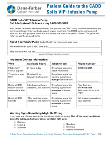
CHAPTER 5CADD FILE NAMINGTRAFFIC DESIGN CADD FILE NAMINGTRAFFIC DESIGN - ELECTRICAL DESIGN CAD FILE NAMINGDESIGN TYPET4007TCS01.dgnT Traffic DesignE Electrical DesignDESIGN TYPE TRACS NOTYPE OF SHEET (SEE BELOW) TWO DIGIT (MIN) SHEET NUMBERTYPE OF SHEETTRAFFIC DESIGNELECTRICAL DESIGNTCS Traffic Control Sheet(s)TCD Traffic Control Detail Sheet(s)Sheet(s)TCQ Traffic Control Quantity sheet(s)MOT Maintenance of Traffic Sheet(s)PMS Pavement Marking Sheet(s)Marking Detail Sheet(s)PMN Pavement Marking Notes Sheet(s)SIG Signal Sheet(s)STS Signal/Electrical General Notes TCN Traffic Control NoteSGN Signal General NotesLIT Lighting Sheet(s)ELD Electric Detail Sheet(s)UGR Underground Conduit sheet(s) PMD PavementINT Interconnect Sheet(s)FMS Freeway Management Sheet(s) SDS Sign Detail Sheet(s)LRP Loop Replacement Sheet(s) SLS Sign Locations Sheet(s)SLT Sign Lighting Sheet(s)SSS Sign Summary Sheet(s) SFS Sign Formats Sheet(s) SNS Signing Notes Sheet(s) XRS Crossroad Sheet(s)Example: T4007SDS15.dgn8
REFERENCE FILE NAMESBase files (reference files) shall conform to the above structure with the following exception: An "X" shall beplaced at the beginning of the file name.TRAFFIC DESIGNPMB Pavement Marking BaseSSB Sign Summary BaseTCB Traffic Control Base SNB Signing BaseBDR Border FileELECTRICAL DESIGNCSB Conduit Schedule BaseSSB Pole Schedule Base SFB Sign Format BaseExample: XT4007TCB.dgn (Add two digit Sheet number if needed)9
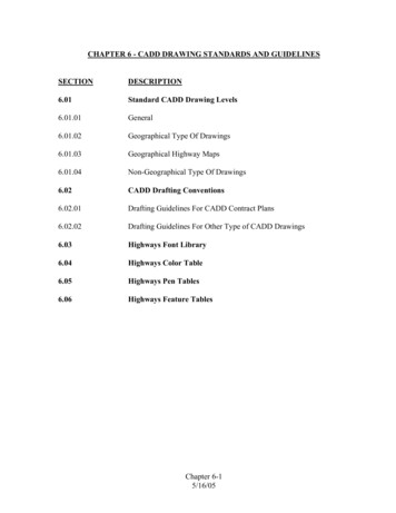
CHAPTER 6 ooo o REFERENCE FILESWhile working with reference files;Try to use the same logical name for the same file in every sheet. The logical name should be the last 2 or 3characters of the file name or a unique identifier that relates to the type of reference file.Example: xh6301tpo.dgn xtpoExample h6301des.dgn desExample h6301xs.dgn xsIf the reference file is attached multiple times to the same sheet, the top left instance of the reference file shallbe coordinately correct. Additional attachments shall use an identifier such as, top or left.Logical names for sheets with multiple instances of the same reference files will be as stated above. Example:lft-xtpo, rght-xtpoAll reference files should be clipped using a shape drawn on level 295 (RW-Work-1). This level is a no-plot level.The shape may be on a construction level if desired.If possible, set the override color, weight, and style values in the reference file itself, then when working in theactive sheet the overrides can be easily set by clicking on “update levels”.BORDER FILESBorder files shall use cell trafd, located in Traffic V8i.cel. The border file should contain only the cell trafd, andany title block information that is used by all sheets in the set. Unless there is a special circumstance, only oneborder file should be used per project.When attaching the border file to the active sheet, the border reference file may be scaled to accommodate thedrawing. The border is one of the very few references that may be scaled or rotated.USING PDFS AS A REFERENCEAlthough MicroStation V8i has the ability to use PDFs as a reference choice, they should not be used as apermanent attachment, but rather as an aid to the drafting process.USING REFERENCE FILES FROM OTHER ADOT GROUPSFiles referenced from any in-house source (Roadway or Bridge for example) should always be referenced fromthe source folder and never copied into the Traffic project folder.REFERENCES & ACTIVE LINESTYLESCALEWhen developing a file that will be used as a reference, care should be taken to ensure that the ActiveLineStyleScale (ALSS) is set to 1. The Active LineStyleScale (ALSS) is a number that tells MicroStation how to scalea custom line style. The 7 built in line styles are not affected by the ALSS.Working with Active LineStyleScales (ALSS) can be a bit tricky if care is not taken when developing the referencefile. When creating a base file for Marking plans, for example, setting the ALSS to any other number than 1 canresult in the pavement marking line styles not being to scale when measured on a plan sheet.All base files should be drafted at 1:1, and the Active LineStyleScale should be set to 1.A Marking Plan example: Marking plans are typically 40 scale. The border reference file has been scaled down10
by 0.4 and moved and rotated to fit the area of interest. The ALSS for this sheet should also be 0.4. By setting theactive sheet’s ALSS to 0.4, however, changes the dimensions of the pavement marking line styles, and they areno longer correct. By using the steps below this can be remedied.When attaching any reference file, the user is greeted by an Attachment Settings dialog box for that uniquereference file. The user can also open this dialog box by double clicking on the highlighted reference in theReferences dialog box. Below is a partial screen shot of the Attachment Settings dialog box:By setting the Global Linestylescale to Master, the Active LineStyleScale set in the active sheet is ignored for thatattachment. Pavement marking line styles will then display as intended.11
CHAPTER 7PRINTING AND PLOTTINGPrint Organizer is a utility for creating, managing, and publishing project deliverables and is a replacement for theBatch Print utility. Additional Printing enhancements include changes in the Print dialog for single sheet printing.For both on-the-fly printing, or when using Print Organizer, there are three main components to printing orplotting; the plot driver, the pen table, and the print style.The Plot Driver contains information needed by MicroStation and Windows to successfully convert and send yourdrawing to the device.Resymbolization is the process of changing characteristics of elements within a design file. When these changesare applied to printed output, the process is referred to as print resymbolization. Pen tables and design scriptscontrol print resymbolization. Pen tables let you remap any of the characteristics associated with design fileelements for the printed output.Print styles are named sets of print definition properties, such as scale, rotation, and color, that allow you tocreate print sets in a consistent and automated manner.While the way print drivers and pen tables are created and their file structure has changed, they continue tofunction much the same as they did in V8. The extension for print drivers has changed from .plt to .pltcfg, andthe format of the plot configuration files have changed from ascii to XML.Below are the print drivers available for use to Traffic Design. They can be found at:V:\Traffic\Dev V8i\Printers \The print driver does not directly affect whether or not printing in grey scale is available or not; that isdetermined by the pen table. The printer driver names that include “non” in the file name will automatically loada pen table that does not support grey scale. When a print driver is selected and loaded, the appropriate pentable will also be loaded. Pen tables may be used with any print driver to achieve the desired results.12
Here are the pen tables available to Traffic Design.Half traffic.tbl – This is the “generic” pen table and works best in most situations.None.tbl –Use this table when printing in color.Normal.tbl – prints everything in black and white, no greys or colors.Subdue.tbl – Greys out all “existing” levels in the active file as well as all reference files.Levels 1-24, 29, 31, 59-61, and colors 227 & 228 will plot in grey.Color 227 RGB 170, 170, 170 (lighter)Color 228 RGB 130,130,130 (darker)13
CHAPTER 8SET UP FOR TYPICAL PLAN SHEETSSIGNING SHEETSSIGNING LOCATION SHEETS:Signing location sheets are plan sheets that show an image of the sign (cell), and the post symbol geometricallylocated relative to the roadway. In some cases, these sheets are combined with Pavement Marking Sheets. Inany case the following applies.When labeling the signs, three pieces of information are required to accompany the sign cell: SummaryReference: this is the label that refers the reader to the correct sign on the Summary Sheet. Typically this is thedirection and mile post (E123.33, or N321.12).Condition: This label indicates the state of the sign, New or Existing.Action: This label shows what is intended for the sign. “Remove Existing”, “To Remain” are some examples of theAction Label.When placing sign cells, or importing signs from SignCAD, attention to the scale and proportionality of the signcell should be taken.Sign Location plans (Main Line) are generally drawn at 100 scale. Sign Location plans (Cross Roads) are generallydrawn at 200 scale.When combined with Striping, the centerline line is not shown, however, the stationing tick marks are alwaysvisible.SIGN SUMMARY SHEETS:Sign Summary sheets contain sign installation data (number of posts, legend, etc.). This data is sometimesgenerated in Excel and then linked to the summary sheet. Linked Excel data is very convenient because the datacan be manipulated in Excel perhaps much easier than in MicroStation. Additionally, the Excel data can be usedfor other purposes as well.We have access to Axiom’s Office Importer. This application provides a convenient way to import Excel data intoMicroStation and is great for Sign Summary Sheets.SIGN FORMAT SHEETS:Sign Format sheets show the output from SignCAD. Experimentation and experience led to the informationprovided below by Richard Moeur.14
Excerpt from an email by Richard Moeur, dated August 10, 2009.The SignCAD MDL settings that I used for placing the signs in MicroStation are as follows:Active Scale (in MicroStation): 1.00Rotation Angle: 0Geometry Scale: 1.00Master Units: Inch (NOT feet or meter)Geometry Level: 54Dimension Level: 54Include Dimensions: YesColor Fill: NODimension Sizing: Use SignCAD SizeI believe that the combinations that provide the best balance between appropriate sign size and legibledimensioning are as follows:Large & medium mainline signs - Plan sheet scale: 1" 25'SignCAD dimension scale: 1:50Ramp/crossroad/small mainline signs - Plan sheet scale: 1" 12.5'SignCAD dimension scale: 1:25PAVEMENT MARKING SHEETSMainline Pavement Marking plans are typically drafted at 40 scale. Crossroad marking plans are typically draftedat 40 scale. Occasionally, 50 scale is used.Text for proposed marking labels are drawn with a weight of 4.The text sizes follow the rules as described above in Chapter 2. Call outs use title case, notes use sentence case.Pavement Marking sheets will typically show any new edge of pavement (EOP) line work as existing. When theContractor begins to lay down the markings, the roadway work has been completed so the EOP should bedisplayed as existing. One way to accomplish this is to use level overrides. From Level Manager set theappropriate level overrides for Roadway’s “MAS” file to CO 16, LC 3, WT 2. The level override option must beon for overrides to display.The weight of the pavement marking line work should generally be ½ of the actual width of the marking.Examples: a 12” wide stop bar would be drawn at a weight of 6, a 6” line would be drawn at a weight of 3, etc.15
TRAFFIC CONTROL SHEETSTRAFFIC CONTROL GENERAL NOTES:Sentence case shall be used for all notes. Sentence case uses proper grammar and punctuation. Avoid usingabbreviations when writing notes.MAINTENANCE OF TRAFFIC SHEETS:Sentence case shall be used for all notes and comments. Sentence Case uses proper grammar andpunctuation.TRAFFIC CONTROL QUANTITIES SHEETS:Text for bid items, element of work descriptions, and other text contained within the quantities grid shall be titlecase. The first character of each word shall be capitalized. Exceptions to this are words defined as definitearticles (“the”), indefinite articles (“a”, and, “an”) and coordinating conjunctions (“and”, “but”, “if”, “or”, “for”,“yet”, “so”, "non" and “nor”) these generally are not capitalized.TRAFFIC CONTROL DETAIL SHEETS:Traffic Control Detail sheets typically are drawn at a scale of 40.Traffic Control Detail sheets will include a variety of elements such as notes, sign cells, and detail graphics. Careshould be taken when importing sign cells. All signs should be proportional and the size consistent with the restof the plan set. A Symbol legend is provided in the cell library and should be used.16
CHAPTER 9 RECORD DRAWINGSARCHIVING PROJECTSThe following are general guidelines on the assembly of record drawings (as-builts): Copy and save signed & sealed plans from Road Portal or Data Warehouse.Set up new CADD pages with plot shapes and rasters in pages of the plans 20 sheets at a time depending on sizeof the plan set.Once plans are rastered in CADD, perform red-lining and clouding per documentation from District.Determine total number of pages, including changes & addenda and use information to perform numbering anddating of the plans.After completing redlines, clouding, numbering and dating you are ready to produce final PDF of plan set.Once final half-size is created, send to Resident Engineer (RE) for review and approval.Once the RE approves the record drawing set, create a new PDF/A set in both half-sized (11”x17”) and full-sized(34”x22”). Once this is complete, send to the RE, Project Resource Office (PRO), and design engineer.Verify Project Resource Office (PRO) has received final approval from RE (or forward along if you already haveemail available).The final record drawings are usually sent through ShareFile.For more information on record drawings, please see ADOT’s Record Drawing Guidelines , administered by theProject Resource Office.17
CHAPTER 10 TOOLSTHE TRAFFIC DESIGN PULL DOWN MENUThe purpose of the Traffic Design MicroStation Pull Down Menu is to help the user find and use proper cells,tools, information, and to assist the user to following Traffic Design CADD Standards.Traffic Design’s MicroStation Pull Down Menu is a work in progress. As new items or new suggestions becomeknown, the menu will evolve. It is recommended that the user take a tour through the menu to see what isavailable, and to suggest items that could be added.AXIOM OFFICE IMPORTERThis utility is used to import data from Excel into MicroStation. This utility seems to work quite well when linkingSign Summary data. A revised version of the normal sign summary spreadsheet is available atV:\Traffic\Dev V8i\CADD Friendly SSS.xls. This revised addition has had some column widths adjusted so that theimported image matches the line work of the sheet.ROTATE TEXT TO LINEThis MDL application rotates an existing text element to match the angle of a line, linestring, or shape. Thisapplication does not have a dialog box.To load and this application:Go to the VBA Tools pull down menu and choose “Rotate Text to Line”Follow the prompts, pick and accept the line segment first. Pick and accept the text to rotate.A few things about this application: if the line was drawn "backwards" the text will rotate to be backwards also,but it’s possible to have the application activate the rotate command (at 180 ) so the text can be rotated ifneeded. If not, simply enter a reject.18
ROTATE ELEMENT TO LINEThis VBA tool works much like the rotate text tool. Snap to the first end, then to the other end of a line, and thenpick the element to rotate.ADD LENGTHAs the name implies, this VBA sums lengths of various element types. The resultant can then be pasted into thedrawing.Note, pasted text will assume current symbology and attributes.19
ARC DATAThis VBA displays information about a selected arc.Note, Pasted text will assume current symbology and attributes.STRAIGHTEN TEXTThis VBA will rotate a text element to be horizontal with the current.20
CHAPTER 11 MICROSTATION INTERFACE CUSTOMIZATIONMENUSGENERAL INFORMATION ON USER CUSTOMIZATIONSEvery user has a location on the V: drive (V:\Traffic\Users\[RACF ID]\v8i\) where they may put theircustomization files. Pull down menus, as well as icon menus would be placed in the\V8i\DGNLIB\Interface\ folder. A custom function key menu would be placed in \V8i\FKEYS\The user may even wish to have their own cell libraries, macros, or other enhancements that are unique to thatuser. MicroStation is configured such that if an appropriate file is placed in the appropriate folder it will be readand executed automatically by MicroStation at start up.FUNCTION KEYSFunction keys are great. Every user should develop a set of function keys that suits their drafting style. The keyto creating any kind of menu item in MicroStation is knowing the key-in for the command.Multiple commands can even be strung together by separating them be a semi colon (;). Below are someexamples of typical function key key-ins.active angle pt2AM dks adot traffic menu.dgnlib, screen1,sc1,s1drop complexchoose prevchoose nonechoose elemspin origpla fence blockInputmanager Menu DONPopvba load Rotate Elm.mvba; vba run Module1.GetRotationSET CURSOR SMALL;ky 2;aa 0;as 1;LOCK SNAP KEYPOINTSNap Nearest21
Extend lineactive axis 30;ky 2;LOCK AXISchange element extendedmacro K:\Rdwy\191214000-Williamson Valley Road\CADD\Sheet Num\add del tagsaa 90aa 0SHOW REFMATCH ELEMENTVIEW PREVIOUSLOCK GGROUPlv 59;co 59;wt 2;ft 3;macro chng-tb FITFIT ALLSET CURSOR FULL; ky 2ZOOM IN 1.8ZOOM OUT 2.3snap intersectionmacro kha-match elementchoose previousview off 1;view on 1;fit all;selview all;filedesignchange text case titlecasechange text case firstcapital22
APPENDIX 1 TRAFFIC DESIGN DRAFTING GUIDE EXAMPLE SHEETSThe following sheets provide examples of CADD methods which follow these guidelines.
APPENDIX 1 TRAFFIC DESIGN DRAFTING GUIDE EXAMPLE SHEETSADVANCE WARNING, TRAFFIC CONTROL PLAN
APPENDIX 1 TRAFFIC DESIGN DRAFTING GUIDE EXAMPLE SHEETSBRIDGE REPAIR, TRAFFIC CONTROL DETOUR
APPENDIX 1 TRAFFIC DESIGN DRAFTING GUIDE EXAMPLE SHEETSCULVERT INSTALLATION, TRAFFIC CONTROL DETOUR
APPENDIX 1 TRAFFIC DESIGN DRAFTING GUIDE EXAMPLE SHEETSPAVEMENT MARKING NOTES AND QUANTITIES
APPENDIX 1 TRAFFIC DESIGN DRAFTING GUIDE EXAMPLE SHEETSGORE PAVEMENT MARKING PLANS
APPENDIX 1 TRAFFIC DESIGN DRAFTING GUIDE EXAMPLE SHEETSURBAN STATE ROUTE WITH MAJOR INTERSECTION PAVEMENT MARKING PLANS
APPENDIX 1 TRAFFIC DESIGN DRAFTING GUIDE EXAMPLE SHEETSURBAN STATE ROUTE (HAWK) PAVEMENT MARKING PLANS
APPENDIX 1 TRAFFIC DESIGN DRAFTING GUIDE EXAMPLE SHEETSRAMP PAVEMENT MARKING AND SIGNING
APPENDIX 1 TRAFFIC DESIGN DRAFTING GUIDE EXAMPLE SHEETSROUNDABOUT TRAFFIC CONTROL, PAVEMENT MARKINGS, SIGNING AND LIGHTING
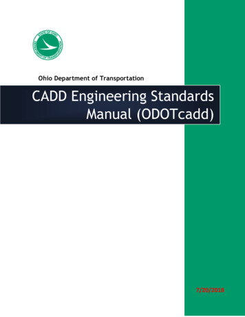
APPENDIX 617171819181920202121222223232424ADOT LEVEL STRUCTUREDESCRIPTIONGRID TICKS, LINE TERMINATORSSPOT ELEV., PHOTO AND PRIMARY CONTROL POINTSSECTION CORNERS, QUARTER CORNERS, RANGE LINES, CENTER OF SECTION,PHOTOGRAMMETRY - TEXTMONUMENTS, BOUNDARIES: CITY, COUNTY, STATE, PARK, FOREST,RESERVATION - TEXTEXIST. INDEX CONTOUR LINES AND TEXTEXIST. INTERMEDIATE CONTOUR LINES - TEXTEXIST. VEGETATION - TEXTMAPPING SYMBOLS: WATER ITEMS AND TEXTEXIST. MAN-MADE TOPOGRAPHY: BUILDINGS, NOISE WALLS,BILLBOARDS, FOUNDATIONS, DRIVEWAYS, SIDEWALKS, CATTLE GUARDS,PUMP HOUSES, ETC.TEXT FOR LEVEL 9 ITEMSEXIST. UTILITIES 9NOT COVERED BELOW), RAILROADS,STANDPIPES, WELLSTEXT FOR LEVEL 11 ITEMSEXIST. MINOR DRAINAGE ITEMS: CATCH BASINS, MANHOLES, STORM DRAINS,SANITARY SEWERS, DITCHES, DIKES, CANALS, DAMS, GABIONS, HEADWALLS,BERMS, PIPES, END SECTIONS, DOWNDRAINS, SPILLWAYS, APRONS, PIPEOUTLETS, RIPRAP, BANK PROTECTIONTEXT FOR LEVEL 13, TEXT FOR LEVEL 22EXIST. EASEMENT AND PERMIT LINES, TEXTEXIST. EDGES OF ROADWAYS, GORE PAVING, GRADER ROADS,TURNOUTSEXIST. TRAFFIC ITEMS: X-WALKS, ROADWAY STRIPPING, SIGNAL AND LIGHTPOLES. ALL SIGNS AND DELINEATION. EXIST. SIGNSTEXT FOR LEVEL 17ROAD NAMES, TEXT FOR LEVEL 16 ITEMSEXIST. NON SURVEYED ROADWAY CENTERLINES WITH TICK MARKS/ NEW TOP OF PAVEMENT (TYP SEC)EXIST. NON SURVEYED ROADWAY CENTERLINE ITEMS: BEARINGS,STATIONING, EQUATIONS, CURVE DATA, ID FOR: PC, PI, PTEXIST. MAJOR DRAINAGE ITEMS: BRIDGES, BOX CULVERTS,RETAINING WALLS, MAJOR CHANNELS, STRUCTURAL PLATE PIPES, TUNNELS.EXIST. CHANNELIZATION ITEMS: CURBS, GUARDRAILS, IMPACTATTENUATORS, CONCRETE BARRIERS (MEDIAN AND HALF),BARRICADES, CHAN LINK CABLE BARRIERSTEXT FOR LEVEL 23 ITEMSADOT Traffic Design Group CAD Standards
9504950NORTH ARROW, MILEPOST MARKERS, ROADWAY DIMENSIONS,MATCH LINES AND OTHER MISCELLANEOUS ITEMSALL MISCELLANEOUS CENTERLINES: SURVEY, OFFICE, ETC. MISCELLANEOUSCENTERLINE ITEMS: BEARINGS, STATIONING,EQUATIONS, CURVE DATA, ID FOR: PC, PI, PT. LOCATION SERVICES: ALL NEWCENTERLINES AND CENTERLINE ITEMSNEW CONSTRUCTION CL WITH TICK MARKS, CL STATIONINGNEW CONSTRUCTION CENTERLINE ITEMS: BEARINGS, CURVE DATA,EQUATIONS, ID FOR: PC, PI, PTEXIST. FENCES, RIGHT OF WAY MARKERS AND LINES - TEXTNEW FENCES, RIGHT OF WAY MARKERS AND LINES - TEXTEXIST. ACCESS CONTROLNEW ACCESS CONTROLRW PROPERTY LINESNEW EDGES OF PAVEMENT, TURNOUTS, GRADER ROADS, SAW CUTSTEXT FOR LEVEL 35 ITEMSNEW INTERMEDIATE AND INDEX CONTOUR LINES, NEW CUT ANDFILL LINESNEW MINOR DRAINAGE ITEMS: CATCH BASINS, MANHOLES, STORM DRAINS,DITCHES, DIKES, CANALS, DAMS, GABIONS, HEADWALLS, END SECTIONS,BERMS, DOWNDRAINS, SPILLWAYS, PIPE OUTLETS, APRONS, PIPES, RIPRAP,BANK PROTECTION / DRAINAGE CHANNEL(TYP SEC)TEXT FOR LEVEL 38 ITEMS (NEW MINOR DRAINAGE ITEMS). TEXTFOR LEVEL 48 ITEMS (NEW MAJOR DRAINAGE ITEMS)NEW UTILITIES (NOT COVERED BELOW), RAILROADS, STANDPIPES,WELLSTEXT FOR LEVEL 40 ITEMSNEW MISCELLANEOUS ITEMS (HAZARDS): CATTLE GUARDS, CONCRETEBARRIERS, (MEDIAN AND HALF), IMPACT ATTENUATORS, GUARDRAILS,BARRICADES, BLOCK FENCES, CHANLINK CABLE BARRIERS, NOISE WALLS, TRAFFIC CONTROL ITEMS - CONES,VERTICAL PANELS, FLAGGING TREESTEXT FOR LEVEL 42 ITEMSNEW MISCELLANEOUS ITEMS (ROADWAY EDGES), GORE PAVING, CURBS,SIDEWALKS, DRIVEWAY, ROADWAY SHOULDERS / CURBAND GUTTER (TYP SEC)TEXT FOR LEVEL 44 ITEMSNEW ROADWAY STRIPPING ITEMS (PAVEMENT MARKINGS); 0 FOR WHITE, 17 FORYELLOW.TEXT FOR LEVEL 46 ITEMS - DIMENSION LINES AND TEXT FORSIGNING & MARKING SHEETSNEW MAJOR DRAINAGE ITEMS: BRIDGES, BOX CULVERTS, TUNNELS, RETAININGWALLS, PUMP HOUSES, MAJOR CHANNELS,STRUCTURAL PLATE PIPESNEW LIGHT POLESNEW PULLBOXES AND CONDUITS, CABINETS, LOOP DETECTORS,ADOT Traffic Design Group CAD Standards
W DRAINAGE EASEMENTTEXT FOR LEVEL 49 AND LEVEL 50 ITEMS, TEXT FOR POLESCHEDULENEW SIGNALS & LUMINAIRSTEXT FOR LEVEL 52 ITEMS - CONDUCTOR SCHEDULE, PHASEDIAGRAMSNEW SIGNS - TEXT - CHANGEABLE MESSAGE SIGNSLANDSCAPE DETAILS / INDEX OF SHEETS TEXT - SIGNING SHEETSTEXT, GENERAL NOTESTEXT FOR LEVEL 55 ITEMSIRRIGATION DETAILSTEXT FOR LEVEL 57ALL AREA PATTERNING AND SHADING / SLOPE TEXT (TYP SEC)STANDARD GRID - PROFILE SHEET (1 INCH)STANDARD GRID - PROFILE SHEET (INTERMEDIATE)PLAN SHEET TE
3 . The purpose of this manual is to establish uniform policies and procedures to ensure compliance with the Traffic Design Group's Computer Aided Design and Drafting (CADD) standards, to produce a plan set that is consistent in