Transcription
Deployment GuideJuly-2015 rev. ADeploying Array NetworksAPV Series Application Delivery Controllerswith VMware Horizon View
1 Introduction . 21.1 VMware Horizon View . 21.2 Array Networks APV Series Appliances . 21.3 Prerequisites & Assumptions . 22 VMware View Load Balancing . 32.1 VMware View Servers . 32.2 Port Protocol Uses . 32.3 View Client Connection Process . 43 Deployment Overview . 63.1 Internal Client Access: Load Balancing Connection Servers. 63.1.1 Scenario 1 – L7 Load Balance the First Connection, with Session Persistence . 63.1.2 Scenario 2 – L4 Load Balance All View Connections with IP Persistence . 63.2 External Client Access; Load Balancing Security Servers. 63.2.1 Scenario 3 – L4 Load Balance all View Connections with IP Persistence . 64 Configuration Steps . 84.1 Scenario 1 – L7 Load Balance the First Connection, with Session Persistence . 84.1.1 View Server Configuration . 84.1.2 APV Configuration . 94.1.3 Validate the Configuration & Application. 144.2 Scenario 2 – L4 Load Balance All View Connections with IP Persistence . 154.2.1 View Server Configuration . 154.2.2 APV Configuration . 154.2.3 Validate the Configuration . 184.3 Scenario 3 - L4 Load Balance All View Connections with IP Persistence . 194.3.1 View Security Server Configuration . 194.3.2 APV Configuration . 194.3.3 Validate the Configuration . 225 Summary .246 Appendix: .256.1 Configure Static NAT for Server Access. . 256.2 Configure SSL Virtual Host . 256.3 Configure HTTP to HTTPS Redirect . 276.4 Disable Server Certificate Check . 286.5 Sample APV CLI Configuration . 281
1 IntroductionThis guide details the configuration of Array Networks APV Series application deliverycontrollers for deployment with VMware Horizon View. It includes details of ports/services thatmust be load balanced, topology considerations for the various VMware Horizon View servers,and steps on how to configure the appliances.For an introduction to setting up an APV Series appliance, as well as more technical information,please refer to our quick-start guides and full administration manuals for the appliance’s WebUI.1.1 VMware Horizon ViewVMware Horizon View (formerly VMware View) is a virtual desktop infrastructure solution thatsimplifies desktop management and provides users with access when needed, regardless oftheir location. For high availability and scalability, VMware recommends that multiple ViewServers be deployed in a load-balanced cluster.Please refer to the following VMware link for additional Horizon View architecture and -60architecture-planning.pdf1.2 Array Networks APV Series AppliancesArray Networks’ APV Series provides a strategic point of control of optimizing the availability,security and performance of enterprise applications, IP data services and data center equipment.Leveraging robust and powerful distribution algorithms, health check mechanisms and failovercapabilities, the APV Series maintains connections, ensures persistence, directs traffic awayfrom failed data centers, and intelligently distributes application services between multiple nodesand locations for optimized performance and availability.APV Series ensures that both end users and administrators obtain the optimal user experienceby creating a highly available and scalable platform that achieves the highest levels of reliabilitythrough network optimization.The APV Series is available as a dedicated hardware appliance or as the vAPV virtualapplication delivery controller.1.3 Prerequisites & AssumptionsIt is assumed that the reader of this deployment guide is a network administrator or a personotherwise familiar with networking and general computer terminology. Software versionssupported:VMware Horizon View: View Connection Server v5.2, v5.3, v6.x and laterArrayOS APV 8.4.0.x, 8.5.0.x and laterVerify that each View Connection Server instance or security server has a security certificatethat can be fully verified by using the host name that you enter in the browser.In this example, the View clients are running the Windows 7 Operating System.2
2 VMware View Load BalancingTo support VMware Horizon View high availability, the best practice is to load balance twoSecurity Servers or Connection Servers.2.1 VMware View ServersVMware Horizon View supports two types of servers:Connection ServerThe View Connection Server acts as a broker for client connections. It authenticatesusers through Windows Active Directory and directs the requests to the appropriatevirtual machine, physical or blade PC, or Windows Terminal Services server. TheConnection Server can be the gateway for the View Client to access the virtual desktopmachine.Security Server (optional, for external access)A View Security Server is a special instance of a View Connection Server that runs asubset of View Connection Server functions. A Security Server is used to provide anadditional layer of security between the Internet and the internal network. A SecurityServer resides within a DMZ and acts as a proxy host for connections inside the trustednetwork. Each Security Server is paired with an instance of View Connection Server andforwards all traffic to that instance.2.2 Port Protocol Uses 443 TCP HTTPS3
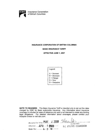
4172 TCP PCoIP 4172 UDP PCoIP 8443 TCP Blast (HTML Access)2.3 View Client Connection ProcessVMware Horizon View clients have two connection stages to access the View Desktops. Theyare:First Connection: Initial connection, access the portal, logon and authentication, obtainthe session data (including Virtual Desktop access information), etc. We refer as to thisas portal access (HTTPS/443). This type of connection is always load balanced by theAPV Series.Second Connection: The client connects to the Virtual Desktop machine (per sessiondata). It can be RDP (HTTPS/443), Blast (TCP/8443), or PCoIP (UDP/TCP, port 4172).Depending upon the View Servers’ (or Security Server) configuration, the secondconnection can bypass or NAT through the APV Series.Figure 1: View Client Connection ProcessThe point at which the second View Client connection connects is controlled by the View Server(or Security Server External URL) Settings. It can be: Direct access to the Virtual Desktop machine, bypassing the APV and View Servers.This is the default for View Servers; the settings are no HTTP(S) Secure Tunnel, noPCoIP Secure Gateway, and no Blast Secure Gateway. Use the View Server as the proxy for the View Clients. This option requires configuringan external URL for the Connection Server. For example, if 10.1.60.26:4172 is used, theexternal firewall (or APV Series) would NAT 10.1.60.26 to the Connection Server.4
Persistence (aka Server Affinity). This requires that View client requests are forwardedto the same View Server for the duration of the session. This can be achieved usingeither source IP persistence or application cookie (JSESSIONID or insert cookie)persistence for HTTP/HTTPS. Source IP persistence can incur an uneven load in amega proxy scenario, since one IP is used by many clients. The application cookiemethod is better for load distribution, but requires SSL offloading to see clear text traffic(see below). SSL Offloading (option, required by L7). In this method, View Clients must use HTTPS toconnect to View Manager. If your View Clients connect to load balancers or otherintermediate servers that pass on the connections to View Connection Server instancesor Security Servers, you can offload SSL to the intermediate servers.To learn how to configure View Servers for SSL offload, please see the following VMware c 977-6955-4A7D8438-AD82C5AD9077.htmlTechnical NotePer VMware, if View Clients use smart card authentication, the clients must make HTTPSconnections directly to the View Connection Server or Security Server. SSL offloading is notsupported with smart card authentication.5
3 Deployment OverviewThere are many options to deploy View Servers and the APV Series load balancer. Basically theoptions can be either internal or external clients (with or without View Security Server, or IPusage). Additional options include server persistence, with or without SSL offloading or bridging,and additional health checks for the View Servers.3.1 Internal Client Access: Load Balancing Connection Servers3.1.1 Scenario 1 – L7 Load Balance the First Connection, with Session PersistenceIn this scenario, in which the APV Series is load balancing View Connection Servers, theConnection Server is not gateway enabled (or enabled without an external URL). For thefirst connection, the View client will access the APV Series, then the APV applianceselects a Connection Server for login based on the JSESSIONID cookie. Or it can selectan available Connection Server per load balancing algorithm for new a session. For thesecond connection, the View client bypasses the APV Series, and directly connects tothe Virtual Desktop machine (or Connection Server).This scenario requires a single Virtual Service, SSL offload, with cookie persistence forthe View Client to the same Connection Server (the latter allows load distribution amongView Servers to be more even compared with persistent IP). For the second connection,the client directly accesses (or NATs through the APV to) the Connection Server orVirtual Desktop machines for fast access. In this scenario the APV load is reduced sincefor the second connection, Virtual Desktop display traffic bypasses the APV. However,this uses multiple IPs for each Virtual Desktop machine.3.1.2 Scenario 2 – L4 Load Balance All View Connections with IP PersistenceThis scenario provides better security, access control and management by not allowingView clients to directly access Virtual Desktop machines by using a single IP for all Viewtraffic. The Connection Server acts as the Gateway for View traffic and external URLsare configured to utilize the APV virtual services for load balancing.In this scenario, the APV uses a single IP with different ports/protocols for multipleVirtual Services and uses the client IP to ensure that View clients connect to the sameConnection Server for the duration of the session for both the first and secondconnections. The Connection Server has its external URL configured to direct Viewclient traffic to the APV Series.3.2 External Client Access; Load Balancing Security Servers3.2.1 Scenario 3 – L4 Load Balance all View Connections with IP PersistenceIn this scenario, a single IP with multiple Virtual Services with different ports/protocols isused to conserve public IP usage for external clients' access. This scenario also uses IPpersistency to ensure that clients connect to the same Security Server for the duration ofthe session.The View Security Server external URLs are pointed to the APV virtual services. Thefirst and second connections both go through the APV virtual services to access the6
Security Server. The clients need to be persistent to the same Security Server, so IPpersistency is used.In addition, in this scenario if the paired connection is down, the Security Server needsto be marked as down as well.7
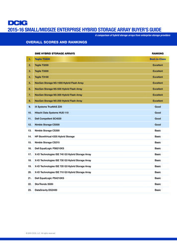
4 Configuration StepsPlease ensure that the APV/vAPV system is accessible from the network, and WebUI isenabled. To access the APV system WebUI, enter https:// apv ip :8888 from the browser. Werecommend using Internet ExplorerLog in; the default user account/password is “array/admin”. For the Array Networks Pilot Login,click Login to enter (default is no password enabled).4.1 Scenario 1 – L7 Load Balance the First Connection, with SessionPersistenceThis scenario uses APV Series load balancing for the first View client connection, with SSLoffload via cookie for server persistence for better load distribution. The second connections willbypass the APV with different FQDNs or IPs.4.1.1 View Server ConfigurationThe Connection Server will let View Clients directly access Virtual Desktop machines orConnection Servers (Gateways).VMware Horizon View configuration:View Configuration Servers Connection Servers Edit.Uncheck all so that View clients can directly access the Virtual Desktop machine.8
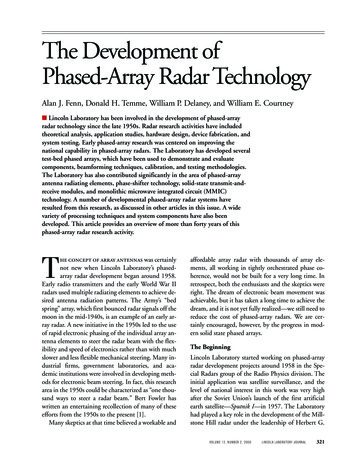
4.1.2 APV ConfigurationDefine the Application Health CheckOn the APV system, the HTTP Health Check Request/Response Table is used toconfigure the content -based Request/Response health check. The APV system healthcheck will send the string and match the response to determine the real service’savailability.RequestIndex0Request StringGET HTTP 1.1\r\n\r\nResponseIndex1ResponseStringVMwareTo configure the content-based Health Check, enter WebUI, Mode: Config.1. Select Real Services from the sidebar. Click the Health Check Setting tab. TheHEALTH CHECK SETTING screen opens.2. For Request Index: 0, enter "GET / HTTP 1.1\r\n\r\n" and for Response Index: 1,enter "VMware". Then click SAVE CHANGES.9
If the View servers have other options to report their health condition, enter the URL andexpected content into the Health Check Request/Response Table.Create Real Services – Connection Server, Secure TunnelOn the APV Series, the Real Services are two View Connection Servers. TheConnection Server is SSL offloading to the APV, so the secured tunnel is via port80/HTTP. Following is the summary of all Real Services that need to be added to theAPV configuration.Real Service Name(ConnectionServer)RealServiceTypeRealService IPReal ServicePortHealthCheckType(index)rs cs01 httpHTTP10.2.40.2680HTTP (0/1)rs cs02 httpHTTP10.2.40.2880HTTP (0/1)Table 1 - Real Services for Connection ServersTo configure the Real Services, enter WebUI, Mode: Config.1. Select Real Services from the sidebar. Real Services (tab) - Add. The “ADDREAL SERVICE ENTRY” screen opens.2. The “ADD REAL SERVICE ENTRY” screen allows you to configure real servers.Enter a unique name for the Real Service Name (rs cs01 http). From the RealService Type pulldown, select “HTTP”. Enter the Real Service IP/Port(10.2.40.26/80) which is used by Connection Server 1.3. Select http as the Health Check Type. For the Request Index and ResponseIndex, pull down the selection and select the corresponding entry (Request Index:0, Response Index: 1) as in the above table. Then click Save to add the RealService.10
4. Repeat steps 1-3 as above: add all Real Services according to Table 1 – RealServices for Connection Servers.Create the GroupThe APV Server Load Balancing (SLB) Group defines the load balancing method andthe set of servers in the group. The following table contains all group information thatneeds to be entered into the APV system. Using the application session cookie methodis recommended to achieve better load distribution.GroupNameGroup MethodGroup MemberPersistence(Cookie:JSESSIONID)rs cs01 httpgp cs SIDrs cs02 httpTable 2 - SLB Group for Connection ServersTo create a SLB Group, from WebUI, Mode: Config:1. Select Groups from the sidebar. The ADD GROUP screen opens.2. Enter a unique name for the Group Name; in the example we used “gp cs SID”.From the Group Method pull down menu, select the “Persistence”, Session Type:string, First Choice: Least Connections. Click Add to create the SLB group.3. To add Real Services to the SLB group, open the GROUPS LIST by doubleclicking on the SLB Group (gp cs SID). The GROUP INFORMATION screenopens.4. Under the “GROUP MEMBERS” section, click on “Add”, and the ADD GROUPMEMBER screen opens.5. From the Eligible Reals pull down menu, select “rs cs01 http”, click Save &Add Another and select “rs cs02 http”. Then click “Save”.11
6. To add the persistence cookie information, select the group gp cs SID, then pulldown to access the PERSISTENCE LIST. Click Add, and the ADD ENTRYPERSISTENCE screen opens.7. For both request and response Modes, select Type: cookie and Field Name:JSESSIONID. Click Save to enter the cookie information.Create the Virtual ServiceFollowing is the one-arm Virtual Service information that used for this example. For atwo-arm configuration, the SLB Virtual Service and the Connection Servers are ondifferent network segments. If the View clients need to be NATed through the APVappliance, see Appendix: 6.1 Configure Static NAT for Server Access.Virtual ServiceNameVirtualService TypeVirtualService IPVirtualServicePortSLBPolicyAssociateGroupsvs view portalHTTPS10.2.40.30443Defaultgp cs SIDTable 3 - Virtual Service for Connection ServerTo create a new SLB Virtual Service, enter WebUI, Mode: Config.1. Select Virtual Services from the sidebar. The “ADD VIRTUAL SERVICE”screen opens.2. Enter a unique name for the Virtual Service Name (vs view portal). Use thecheck box to enable the virtual service. From the Virtual Service Type pull downmenu, select “HTTPS”. Enter the Virtual Service IP and Port (10.2.40.30/443).Use the check box to enable ARP. Set the maximum number of openconnections per virtual service. “0” means unlimited. Depending on which type ofvirtual service is specified, certain parameter fields will appear, change ordisappear. Click “Add” to create the new SLB Virtual Service.12
3. Select the Virtual Service (vs view portal) on the VIRTUAL SERVICE LIST bydouble clicking on it. The VIRTUAL SERVICE INFORMATION screen opens witha new series of tabs for completing the virtual services configuration.4. Pull down to the ASSOCIATE GROUPS section, and from the Eligible vLink orGroups pull down menu select “gp cs SID” and in the Eligible Policies pulldown menu, select “default”. Click Add to associate the Group with the VirtualService.Because the Virtual Service type is HTTPS, we need to associate an SSL Virtual Host –if the SSL Virtual Host was not created previously, see Appendix: 6.2 Configure SSLVirtual Host.5. Select “SSL” from the sidebar. Click Virtual Hosts - Add. The SSL VIRTUALHOST screen opens.6. Enter a unique SSL Virtual Host Name (ssl-vhost1) and select the SLB VirtualService (vs view portal). Then click Save.7. If SSL Virtual Host is not enabled, we need to enable it. To enable it, select “SSL”from the sidebar. Click Virtual Hosts. Double click the SSL Virtual Host on thelist (ssl-vhost1). Then click Virtual Host Settings.8. Under SSL BASIC SETTNGS, check the Enable SSL box if it is not alreadychecked. Then click SAVE CHANGES to enable the SSL.13
4.1.3 Validate the Configuration & ApplicationValidate that the basic configuration is functioning correctly:1. From WebUI, SERVER LOAD BALANCE, Monitoring - Status - VirtualService Status. Select “vs view portal” as the virtual service.2. Verify that the configuration is as intended: HTTPS for the Virtual Service andHTTP for the Real Service.3. Verify that all “Service Status” icons are green.To verify that the View client works properly with the APV Series, from View Clients,enter the URL/IP to access the View portal.14
4.2 Scenario 2 – L4 Load Balance All View Connections with IP PersistenceFor this scenario, all View traffic to the Connection Server will pass through the APV appliance.4.2.1 View Server ConfigurationEnable HTTP(S) Secure tunnel, PCoIP Secure Gateway, and Blast Secure Gateway.Set the external URLs to the APV Virtual Services.4.2.2 APV ConfigurationThe APV system needs to be configured with multiple Virtual and Real Services to proxyall View traffic via a single IP.Define Application Health CheckFor the HTTP content application health check, the request/response configuration canbe the same as Section 4.1.2.Create Real ServicesReal Services are two Connection Servers. The Connection Server will gateway all Viewtraffic, so we need include secure tunnel, PCoIP and Blast support as Real Services.Following is the summary of all Real Services need add to the APV configuration. Thers cs01 http and rs cs02 http configuration are the same as 4.1.2; however we needadd additional real services.15
Real Service Name(Connection Server)RealServiceTypeReal ServiceIPReal ServicePortHealthCheck Typers cs01 httpHTTP10.2.40.2680HTTP (0/1)rs cs01 blastTCP10.2.40.268443TCPrs cs01 pcoip tcpTCP10.2.40.264172TCPrs cs01 pcoip udpUDP10.2.40.264172ICMPrs cs02 httpHTTP10.2.40.2880HTTP (0/1)rs cs02 blastTCP10.2.40.288443TCPrs cs02 pcoip tcpTCP10.2.40.284172TCPrs cs02 pcoip udpUDP10.2.40.284172ICMPTable 4 - Real Services for Connection ServersTo configure the Real Services, enter WebUI, Mode: Config.1. Select Real Services from the sidebar. Click Add. The ADD REAL SERVICEENTRY screen opens.2. Enter a unique name for the Real Service Name; in our example, weentered ”rs cs01 blast”. Select TCP as the Real Service Type, enter IPaddresses/Port “10.2.40.26/8443” which is used by the Connection Server 1Blast service.3. Select TCP as the Health Check Type.4. Repeat steps 1 through 3 to enter all Real Services, using the default healthsetup for TCP/UDP.Optional: Additional Health CheckA Connection Server hosts multiple services; if one of the services is down, we need tomark the whole server as down, so the APV can divert new View client access to other,healthy, Connection Servers. For example, if Blast or PCoIP are down, the APV canutilize the Additional Health Check to mark the portal access as down for a ConnectionServer.Additional HealthCheck NameRealServiceNameHealthCheck IPHealthCheck PortHealthCheck Typeahc cs01 blastrs cs01 http10.2.40.268443TCPahc cs01 pcoiprs cs01 http10.2.40.264172TCPahc cs02 blastrs cs02 http10.2.40.288443TCPahc cs02 pcoiprs cs02 http10.2.40.284172TCPTable 5 - Additional Health Checks for Connection ServersTo configure the additional health checks as a Real Service, enter WebUI, Mode: Config.1. Select Real Services from sidebar; double click the Real Service (rs cs01 http),and then click Additional Health Check.16
2. Under ADD ADDITIONAL HEALTH CHECK, enter a unique name for the HealthCheck Name (ahc cs01 blast in the example). Select the type (tcp), and enterthe target Health Check IP and Port (10.2.40.26/8443). Click Add.3. Repeat steps 1 and 2 to enter all additional health checks from Table 5 –Additional Health Checks.Create GroupsThe following table shows the groups that are used in the example. Since View Clientsneed get to the same Connection Server for different View services, we are using"HASH IP" for this example. As there are multiple groups for a server, we need RealService names for a server in sync (sorted with the same position) among all groups.Group NameGroup Methodgp cs httpHash IPGroup Memberrs cs01 httprs cs02 httpgp cs blastHash IPrs cs01 blastrs cs02 blastgp cs pcoip tcpHash IPrs cs01 pcoip tcprs cs02 pcoip tcpgp cs pcoip udpHash IPrs cs01 pcoip udprs cs02 pcoip udpTable 6 - GroupTo create an SLB Group, enter WebUI, Mode: Config.1. Select Groups from the sidebar. The ADD GROUP screen opens.2. Enter a unique name for the Group Name; in the example we used “gp cs http”.From Group Method pull down menu, select “Hash IP”. Click Add to create theSLB group.3. To add Real Services to the SLB group, on the GROUPS LIST double click toselect the SLB Group (gp cs http). The GROUP INFORMATION screen opens.4. Under the “GROUP MEMBERS” section, click “Add”. The ADD GROUPMEMBER screen opens.5. From the Eligible Reals pull down menu, select “rs cs01 http”, click Save &Add Another and select “rs cs02 http” and “Save”.17
6. Repeat steps 1 through 5 for all other groups and members.Create Virtual ServicesThe following table lists all Virtual Services for the scenario:Virtual ServiceNameVirtualService TypeVirtualService IPVirtualServicePortSLBPolicyAssociateGroupsvs view portalHTTPS10.2.40.30443Defaultgp cs httpvs view blastTCP10.2.40.308443Defaultgp cs blastvs view pcoip tcpTCP10.2.40.304172Defaultgp cs pcoip tcpvs view pcoip udpUDP10.2.40.304172Defaultgp cs pcoip udpTable 7 - Virtual ServicesVirtual Service vs view portal is the same as in Scenario 1. For detailed configurationsteps, please refer Section 4.1.2.To create additional SLB Virtual Services, enter WebUI, Mode: Config.1.Select Virtual Services from the sidebar. The “ADD VIRTUAL SERVICE” screenopens.2.Enter a unique name for the Virtual Service Name (vs view blast). Use thecheck box to enable the virtual service. From the Virtual Service Type pull downmenu, select “TCP”. Enter the Virtual Service IP and Port (10.2.40.30/8443). Click“Add” to create the new SLB Virtual Service.3.Select the Virtual Service (vs view blast) on the VIRTUAL SERVICE LIST bydouble clicking on it. The Virtual Service Information screen opens with a newseries of tabs for completing the virtual services configuration.4.Scroll down to ASSOCIATE GROUPS, from the Eligible vLink or Groups pulldown menu; select “gp cs blast” and on the Eligible Policies pull down menuselect “default”. Click Add to associate the Group with the Virtual Service.5.Repeat steps 1 through 4 to add all remaining Virtual Services listed on Table 7 –Virtual Services.4.2.3 Validate the ConfigurationValidate that the basic configuration is functioning correctly:1.From WebUI, SERVER LOAD BALANCE, Monitoring - Status - VirtualService Status, select “vs view portal”, "vs view blast","vs view pcoip tcp" and "vs view pcoip udp" as the virtual services.2.Verify that the configuration is as intended and that all “Service Status” icons aregreen.18
4.3 Scenario 3 - L4 Load Balance All View Connections with IP PersistenceFor external client access, an APV can be deployed with single IP to load balance all Viewtraffic to the Security Server.4.3.1 View Security Server ConfigurationEach Security Server is paired with a Connection Server. All communications to theSecurity Server are encrypted. Only one IP is used for all View services.On the Security Server, fill out all external URLs and IP addresses as below.In the VMware Horizon View Administrator’s interface, go to View Configuration Servers Security Servers Edit.4.3.2 APV ConfigurationThe APV Series is using L4 with IP persistence to load balance multiple Security Servers.No SSL processing is performed on the APV Series.Additional health checks are needed for the paired Connection Server. In this scenario ifthe Connection Server is down, the front Security Server should be marked as down aswell; otherwise, View clients will not be able to access the Virtual Desktop via thedowned Connection Server.Define Application Health CheckFor this example, the default protocol checks are used.19
Create Real ServicesThe following table shows the Security Server ports that need to be load balanced as theReal Services.Real ServiceName(Security Server)RealServiceTypeReal ServiceIPReal ServicePortHealthCheck Typers ss01 portalTCP10.2.40.27443TCPrs ss01 blastTCP10.2.40.278443TCPrs ss01 pcoip tcpTCP10.2.40.274172TCPrs ss01 pcoip udpUDP10.2.40.274172ICMPrs ss02 portalTCP10.2.40.29443TCPrs ss02 blastTCP10.2.40.298443TCPrs ss02 pcoip tcpTCP10.2.40.294172TCPrs ss02 pcoip udpUDP10.2.40.294172ICMPTable 8 - Real
2 VMware View Load Balancing To support VMware Horizon View high availability, the best practice is to load balance two Security Servers or Connection Servers. 2.1 VMware View Servers VMware Horizon View supports two types of servers: Connection Server The View Connection Server acts as a broker for client connections. It authenticates