Transcription
Paper ID #15838A Modular System for Energy Efficiency Study of Hydraulic ApplicationsDr. Alamgir A. Choudhury, Western Michigan UniversityAlamgir A. Choudhury is an Associate Professor of Engineering Design, Manufacturing and ManagementSystems at Western Michigan University, Kalamazoo, Michigan. His MS and PhD are in mechanical engineering from NMSU (Las Cruces) and BS in mechanical engineering from BUET (Dhaka). His interestincludes computer applications in curriculum, MCAE, mechanics, fluid power, and instrumentation &control. He is a Registered Professional Engineer in the State of Ohio and affiliated with ASME, ASEE,SME and TAP.Dr. Jorge Rodriguez P.E., Western Michigan UniversityFaculty member in the Department of Engineering Design, Manufacturing, and Management Systems(EDMMS) at Western Michigan University’s (WMU). Co-Director of the Center for Integrated Design(CID), and currently the college representative to the President’s University-wide Sustainability Committee at WMU. Received his Ph.D. in Mechanical Engineering-Design from University of WisconsinMadison and received an MBA from Rutgers University. His B.S. degree was in Mechanical and ElectricalEngineering at Monterrey Tech (ITESM-Monterrey Campus). Teaches courses in CAD/CAE, MechanicalDesign, Finite Element Method and Optimization. His interest are in the area of product development,topology optimization, additive manufacturing, sustainable design, and biomechanics.c American Society for Engineering Education, 2016
A modular system energy efficiency study of hydraulic applicationsDue to the growing demand for energy efficient products on the market, the investigation ofenergy usage in product lifecycles is becoming an important factor in design processes. Often, thisproblem is addressed by the analysis of energy efficiency of a product already designed along withits subsequent design improvement. The consideration of energy efficiency at an earlier stage addsto the complexity of the design process, but payoff may be significant in terms of marketdominance. In this paper, the design of a manually powered hydraulic bicycle using energyefficiency as a primary design objective is presented. A laboratory setup is developed to testperformance of the hydraulic system components. Experimental analysis of component behaviorof a functional prototype of the hydraulic system is performed. The analysis result is used to selectcomponents for optimum performance of the system in its desired operational conditions. Themethodology can be utilized in design of similar systems where energy efficiency is a primarydesign objective.1. IntroductionWorldwide, the vast majority of energy is produced from fossil-based fuels resulting in theincrease of carbon dioxide in the atmosphere [1]. In the area of fluid power, the United Statesconsumes about 2 Quads of energy per year with an average of 22% system efficiency [2]. Thedesign of industrial products and processes requiring less energy will significantly impact thedemand of fossil fuel-based energy and its impact on the climate. Production of 2 Quads energycosts about 60B, in process emits 360 million metric tons (MMT) of CO2 to the atmosphereeach year. Since the energy crisis of the 1970s, energy efficiency improvement in most industrialsystems is noticeable, but very little has changed in the fluid power system. Improving thisefficiency by a mere 5% would save fluid power industry about 10B per year, reducing CO2emissions by 65 MMT. A 10% improvement will bring the energy efficiency of fluid powersystems comparable to that of the internal combustion engine, saving the industry 20B per yearand reducing yearly CO2 emissions by 110 MMT. Considering this benefit, industries arelooking for methods to reduce overall energy consumption and maximize the sustainability ofproducts and processes. Achieving this goal is a complex and gradual process and will require a
different design methodology. Both industry and government bodies have made energy savingand energy efficiency a priority in all future operations. In academia, this awareness is leading tovarious curriculum reform. The National Science Foundation funded various projects to updateengineering curricula for the comprehensive teaching of energy in different undergraduateprograms. The NSF funded accelerated testing methodology projects [3] utilizing statisticalmethods to determine the interrelationship between various stress loadings and total energy usein a mechanical system. This established a framework to facilitate the optimum experimentaldesign and energy reduction in the process. The US Department of Energy promotes bestpractices in energy efficiency, reusable energy, waste reduction, and productivity improvementthrough the integration of activities. While energy efficiency and conservation is a novelobjective on its own merit, many consider this essential for the long term sustainability of anindustrial society [4, 5, 6]. Generally, engineering design classes in undergraduate programsfollow a structured problem- solving approaches for solutions of open ended design problems.Besides achieving mechanical integrity of the product and intended product functions, additionalanalysis tools are utilized to achieve other design goals, typically referred to as design for X [7].This includes a variety of design objectives to ensure the long term sustainability of products andprocesses. Design for Environment (DfE), or ecodesign [8, 9] aims to reduce the environmentalimpact in the life cycle of a product by enhancing its design objectives. It may also aim to reduceresource consumption in terms of material, energy, and pollution prevention. Other concepts,such as Design for Disassembly (DfD) and Design for Recycling (DfR) practices [10, 11, 12],would also allow the product designer to have a substantial positive impact on the environmentalaspects of a product’s lifecycle.The incorporation of energy efficiency in a design project will require additional analysis toolsand proven design methodology. Because of the analytical complexity of the subject,experimental methods are more feasible to understand the source and nature of energy loss influid power system. This paper presents an initiative to incorporate energy efficiency in a fluidpowered transportation system design project. Though the methodology is used in the capstonedesign project, it can be beneficial for the design of a mechanical system in general.2
2. Experimental analysis of energy efficiencyThe formulation of accurate analytical model of all energy losses system and its utilization indesign of an energy efficient fluid power system is not expected to be within the reach of mostundergraduate students. It is more viable to study the behavior of a prototype system in thelaboratory and utilize the experimental result to improve the energy efficiency of the system.The prototype would be developed according to system specification in a conventional designprocess. It would be scaled to fit the laboratory limitations if such scaling does not affect thecharacteristics of the system significantly. Additional sensors and process instrumentation wouldbe added to monitor the prototype behavior. In most hydraulic systems, major sources of energyloss are known. After the function of the prototype is verified, energy losses in the system wouldbe measured and tabulated. Often, common sense practices can be quickly adapted in the systemto enhance its energy efficiency without formal design changes. Actual experimental processstarts with operation of the system under variety of conditions and acquiring of process data. Anonlinear regression modeling method is utilized to fit the process behavior with their expectedanalytical nature. Upon the performance of a sensitivity analysis of the process data, parametersmostly effecting the energy efficiency of the overall system are identified. In general,optimization of the energy efficiency model would specify optimal design parameters of thesystem. The study of the process parameters also leads a designer towards specific andinnovative solutions of the design problem.The design process presented in this paper is practiced in a conventional capstone design project,where a group of students are assigned a two semester design project. In the past, student groupswere asked to design a human powered hydraulic system to transport a single person. Withoutusing any direct drive mechanism, the system would transfer the rider’s power to the drivingwheel through the use of a fluid power system. The goal of the design was its functionality,safety, reliability, manufacturability and cost effectiveness. It was implemented as a routine stepby step process of the problem’s definition, concept generation, design analysis, designspecification, component selection and fabrication, prototype development, performance testing,and validation of the design process. Later additional design criteria was added to address theissue of energy usage. This includes capture energy lost due to braking or downhill motion andenergy efficiency of the overall system. This required a new design process with energyefficiency as primary design objective. The most significant sources of energy loss in a hydraulic3
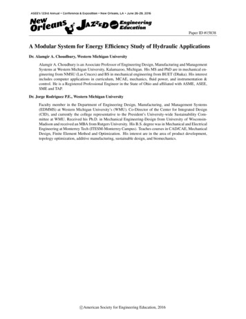
system are the pump, motor, control valves and in fluid throttling process. The design of fluidpower circuit without the throttling of fluid and the use of most efficient control valve wereeasily added to the design process. The challenge was the selection of the pump and motor forthe most energy efficient operation of the system. Manufacturers of the components provideperformance characteristics tested in their normal range of operating conditions. In this hydraulicsystem, pump and motor operate in a broader range of operating conditions. Therefore, theirperformance beyond normal operating conditions need to be determined experimentally.Meaningful analysis of the test data requires sophisticated measurement, data acquisition, andanalysis system in the laboratory. Therefore, a new laboratory is being developed to assiststudent groups with such experiments.In the following, example of an experimental analysis in design of an energy efficient humanpowered hydraulic transportation system is presented.3. Energy efficiency testing laboratoryA laboratory (Figure 1) is developed to test performance of the prototype, variety of systemconfiguration, and a fluid power system in general. For a hands-on study of the process and thedesigned system, one can assemble the components, create the desired application, and study itsperformance. The laboratory is composed of six modules. Using quick connect coupling and aflexible hose, these modules can be connected to create the system under investigation.PumpcontrolPump driveEletric motorSensorsMeasureing instrumentationPump/relief valveVariable flow circuit,valves and accumulatorDAQData displayReservoirControlmoduleData analysis systemHydrualicactuator/motorDirection controlFlow controlHeaterCooler/Heat exchangerActuatorloadingmechanismPressure controlFluid power system design laboratory setupFigure 1. Layout of the test laboratory4
Pump module: This module (Figure 2) has a series of variable displacement pumps to supply afluid power system in general. The pumps are driven by 7.5, 2 and 0.5 HP electric motors withtheir own control (ABB ACS 500) to vary flow rate. A 30 gallon reservoir is used to supply fluidto these pumpsFigure 2. Pump module circuitand other components of the module. A flexible pump mounting fixture is added to allow theinstallation of other pumps in a test system. A solenoid valve operated supply manifold is used toprovide power from individual or combination of pumps. Flow from a hydraulic system returns tothe reservoir through another manifold and cartridge filter. The whole module is mounted on aportable frame and quick connect couplings are used to integrate with other modules as necessary.Flow and conditioning module: This module (Figure 3) will be used to create any flow circuitnecessary for a specific system under consideration. It consists of a bank of stainless steel tubes inlayers which can be connected in a series or parallel using two way direction control valves. Onewould be able to create different types of flow circuit utilizing the tubes, hoses, and directioncontrol valves installed in the module. To ensure the maintenance of physical properties andchemical stability, hydraulic fluid from the actuator is conditioned prior to the return to thereservoir. Hydraulic fluid will be conditioned using a panel filtration unit, a heating unit and a heatexchanger in this module. This allows for testing the performance of a hydraulic system in adesired operating temperature, irrespective of ambient temperature.Actuation module: Hydraulic motors and cylinders required in a system under investigation areinstalled in this module. The module (Figure 4) has flexible mountings to allow for the installationof different hydraulic motor or cylinder. A hydraulic motor is used to drive the pump with desiredtorque and rpm. Motor power is supplied by the flow from the pump module. The load on the5
pump is created by controlling the pressure and flow at the pump exit. To test characteristics of alinear actuator, the motor/pump setup can be replace with appropriate hydraulic cylinders and forcesensors.Instrumentation module: This module has sensors, data acquisition, data processing, and adisplay and control instrumentation. A combined SCXI and PXI chassis based National Instrumenthardware is utilized for this purpose. NI DAQ cards, such as NI PCI-7342, 6024E, GPIB ENET,NI CR10-9073, NI 9213, NI 9205, NI 9901, NI 9977, and other accessories are utilized forFigure 3. Flow and conditioning moduleFigure 4. Actuator module and motor-pump couplingcollecting all process data (pressure, temperature, flow, torque, force, and rpm) in either analog ordigital form. The sensors are configured by the DAQ modules for their excitation and outputsignals. The system also allows sending appropriate signals to process actuators (valves, pumpdrive and temperature controller). LabVIEW program is utilized to integrate the process sensors6
with the analysis and control system. Additionally, Matlab, Automation Studio, and other analysistools are used for further study of process and component behavior based on the data acquired.Control module: This is an external module that uses mainly microcontrollers and programmablelogic controllers (PLCs) in the fluid power process. It replicates a hardware-based control systems,as opposed to the software-based controls included in the Instrumentation Module. It can beexpanded to control other systems besides the fluid power modules, thus allowing for a widerrange of possible projects.4. Experimental analysisThis design project was part of a national design competition among fifteen different universityteams. The success of the design would be determined by performance of the system in a seriesof competitive races. The objective was to design a hydraulic system that would minimizeenergy loss and optimize performance of the system in the races. In the design process, all pumpsand motors meeting the operational requirement were assessed and two sets of pumps and motorsidentified as “Aerospace” and “H3” were selected for testing in the laboratory. A test system isdeveloped in the laboratory that allows operation of the pumps and motors under variable flowrate, pressure, rpm, torque and power. This operational data was imported in Excel for detailedanalysis.Energy analysis and energy efficiency mapping: The goal of the analysis was to determineoverall which pump and motor would operate at higher efficiency during the duration of theraces. Based on the desired speed of the bike in race track, shaft rpm of pump and motor wasdetermined as function of time. Table 1 shows the bike speed, corresponding track length, shaftrpm and its duration. The data is used to calculate a Speed Factor (S) at each pump and motorspeed as fraction of total race time.Si Where,tiT (1)Si Speed Factorti Duration of a specific speedT Completion time of race.For each wheel velocity, the corresponding shaft speed is calculated based on wheel rpm andgear ratio. In the laboratory efficiency characteristics of the pumps and motors are mapped withrespect to shaft rpm and pressure (Figures 5 and 6). Rotational speed and power are measured by7
utilizing an electric motor control system. Appropriate pressure and flow is maintained by usinga pressure relief valve and a flow control valve.Using the efficiency maps of the pump and motor, an overall Efficiency Index (E) is calculatedfor both sets of pump and motor. The Efficiency Index at each shaft speed is given byEi Si iWhere, (2)Ei Efficiency Index i Efficiency at pressure iOverall Efficiency Index isE Ei 1, n j 1, mij (3)Where i and j are for each pressure and speed factorFor the overall calculation speed and efficiency data was used to create a regression model ofefficiency characteristics and calculate efficiency index for any shaft speed and pressure in aspecific design scenario. The result of the analysis are shown in Table 2 and 3. Based on thisanalysis, the highest efficiency index pump and motor were found to be 154.441 and 197.9571for the Aerospace pump and motor respectively.Table 1. Speed factorTherefore, they were chosen in the final design. In a later stage of the design, the efficiencyindex formulation was modified by introducing factors due to size, weight and the cost of pumpsand motors. Because of the low cost, an H3 pump and motor were deemed more suitable in finalcomponent selection.8
Figure 5 Hydraulic motor overall efficiency versus pressureFigure 6. Efficiency mapping of a hydraulic motor5. Design assessmentEffectiveness of this design process is assessed by the success of the design in the competitiveraces among twelve participating university teams. Prior to use of this design process, our systemmet the competition criteria but was not the winner in the races. This design did, however, earnfirst place in the design report as assessed by industry professionals. In terms of its actual9
performance, it earned the overall championship in the competition. Performance testing ofstudent design in the laboratory and effectiveness of such design is shown as an example in thedepartmental senior design project class.Table 2. Pump Efficiency IndexTable 3. Motor Efficiency Index6. ConclusionA modular form of laboratory for experimental analysis of energy efficiency of a hydraulicsystem is developed. The experimental method, type of analysis, and design process is discussed10
in general terms. An example of a hydraulic transportation system, analysis method adapted, anddesign process is presented. The result was a superior design and better realization of designobjectives. The methodology can be applied in principle to achieving energy efficiency in systemdesign.Bibliography1. Energy in the United States, Wikipedia, http://en.wikipedia.org/wiki/Energy in theUnited States2. Estimating the Impact (Energy, Emission and Economics) of the U. S. Fluid PowerIndustry, Oak Ridge National Laboratory report, ORNL/TM-2011/14, 2012.3. Liao, H.T. and Zhang, D. "Statistically Precise and Energy Efficient Accelerated LifeTesting," SAE Int. J. Mater. Manuf., v.4, 2011, p. 992-998.4. Foundation for Global Sustainability, Do You Know What Sustainability Mean?,http://www.korrnet.org/fgs/edu/index.html5. Robert A. Frosch, “Sustainability Engineering (editorial)”, The Bridge 29:1, Spring 19996. UN Environment Program/Industry and Environment, Ecodesign: A promising approachto sustainable production and consumption. Tech. Rep. CP18, 19977. Timkor, S., Haapala, K. and Kumar, V.; New Engineering Design Concepts forSustainable Products, Proceedings of ASEE Annual conference and Exhibition, 2006.8. Design for Environment (DfE) or Ecodesign on/Glossary/Glossary.html, 2006.9. Hollowayu, L., Materials selection for optimal environmental impact in mechanicaldesign, Materials and Design, pp.133-143, 1998.10. Gungor, A., Gupta, S. M., Issues in environmentally conscious manufacturing andproduct recovery: a survey, Computers & Industrial Engineering, 36, pp. 811-853, 1999.11. Burke, D., K. Beiter and K. Ishii, Life cycle design for recyclability, Proceedings of theASME Design Theory and Methodology Conference, Scottsdale, AZ, 1992, DE-42, pp.325– 332.12. Ishii, K. Charles F. Eubanks and Patrick Di Marco, Design for product retirement andmaterial life cycle, Materials and Design, 5, pp. 225–233. 1994.11
12
Madison and received an MBA from Rutgers University. His B.S. degree was in Mechanical and Electrical Engineering at Monterrey Tech (ITESM-Monterrey Campus). Teaches courses in CAD/CAE, Mechanical . the system would transfer the rider's power to the driving wheel through the use of a fluid power system. The goal of the design was its .