Transcription
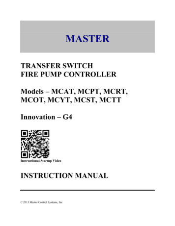
MASTERTRANSFER SWITCHFIRE PUMP CONTROLLERModels – MCAT, MCPT, MCRT,MCOT, MCYT, MCST, MCTTInnovation – G4Instructional Startup VideoINSTRUCTION MANUALC 2013 Master Control Systems, Inc
MASTER – Transfer Switch Fire Pump ControllerG4 – Instruction ManualTABLE OF CONTENTSImportant Safety Information . Page 3General Description and Installation . . Page 4Model Number Construction . Page 5Standard Product Specifications . Page 8Annotated Controller Illustration Page 10Installation . Page 12Connections Page 13Initial Power Up . . Page 17Setup Assistant . Page 18Logging In . . Page 22Menu Functions . . Page 23Advanced Setup . . Page 26Setting Summary Page 28Startup Procedure and Check List . Page 29Operating Instructions . Page 32Downloading History . Page 34Maintenance . Page 35Replacement Parts List . Page 36Drawings:-External Wiring Diagram-Schematic Diagram-Piping ConnectionOption and Modification Drawings-Programmable Option Chassis Wiring Diagram-LPM, Leading Phase Monitor, Supplemental Drawing-SP1 and SP2, Supervisory Power Wiring Diagram-19, 20, 20A, Space Heater Wiring Diagram-30 Single Phase MCAT Wiring External and Schematic DiagramMaster Control Systems, Inc.MC T-G4 Issue 02-v03-2-Lake Bluff, Illinois2019.07.11
MASTER – Transfer Switch Fire Pump ControllerG4 – Instruction ManualIMPORTANT SAFETY INFORMATIONWARNING - DANGER OF LETHAL ELECTRICAL SHOCK AND ARC FLASHHAZARD - USE APPROPRIATE PERSONAL PROTECTIVEEQUIPMENT (PPE) IN ACCORDANCE WITH NFPA 70E.WARNING - TO PREVENT THE POSSIBILITY OF SERIOUS INJURY OR DEATHDUE TO AN ELECTRICAL FAULT, BE SURE THE DOOR(S) ISCLOSED AND LATCHED BEFORE CLOSING ANY OF THEISOLATING SWITCHES AND CIRCUIT BREAKERS OR OPERATINGTHE CONTROLLER.WARNING - THIS EQUIPMENT MUST ONLY BE SERVICED BY QUALIFIEDELECTRICAL PERSONNEL.WARNING - DO NOT DEFEAT ANY INTERLOCKS OR SAFETY FEATURES OREQUIPMENT OR CIRCUITRY.WARNING - FOREIGN VOLTAGE MAY BE PRESENT. CONTROLLERS EQUIPPEDWITH MODIFICATION “SP1” OR “SP2” UTILIZE AUXILIARYBRANCH CIRCUIT POWER WHICH IS NOT SWITCHED ORCONTROLLED BY THE ISOLATING SWITCH (IS) OR CIRCUITBREAKER (CB). ALWAYS TURN OFF OR DISCONNECT THEEXTERNAL SOURCE OF POWER BEFORE ATTEMPTING TOSERVICE THE CONTROLLER.WARNING - BEFORE ATTEMPTING TO MAINTENANCE OR SERVICE THISEQUIPMENT, BE SURE TO FOLLOW THE PLACARD INSTRUCTIONSTO DE-ENERGIZE BOTH THE TRANSFER SWITCH AND FIRE PUMPCONTROLLER.CAUTION - OPENING ONLY THE NORMAL SOURCE CIRCUIT BREAKER (CB-N)WILL CAUSE THE GENERATOR TO START AND THE CONTROLLERTO TRANSFER TO THE EMERGENCY SOURCE AFTER A 10 SECONDDELAY.Master Control Systems, Inc.MC T-G4 Issue 02-v03-3-Lake Bluff, Illinois2019.07.11
MASTER – Transfer Switch Fire Pump ControllerG4 – Instruction ManualGENERAL DESCRIPTION and APPLICATIONMaster combined Manual and Automatic Electric Fire Pump Controllers meet all of therequirements of NFPA-20, Standard for the Installation of Stationary Fire Pumps for FireProtection. They are designed to automatically start an electric motor driven fire pump in theevent of a fire.-Model MCATZ transfer switch fire pump controller combination units provideacross-the-line (direct-on-line) full voltage starting for three phase motor driven firepumps. These controllers are used where local power limitations do not restrict the motorstarting in-rush (locked rotor) current.-Model MCPTZ transfer switch fire pump controller combination units provide partwinding reduced inrush starting for three phase motor driven fire pumps. Thesecontrollers are used where local power limitations restrict the motor starting in-rush(locked rotor) current.-Model MCRTZ transfer switch fire pump controller combination units provide primaryreactor reduced voltage starting for three phase motor driven fire pumps. Thesecontrollers are used where local power limitations restrict the motor starting in-rush(locked rotor) current.-Model MCOTZ transfer switch fire pump controller combination units provide wyedelta (star-delta) open transition reduced inrush starting for three phase motor driven firepumps. These controllers are used where local power limitations restrict the motorstarting in-rush (locked rotor) current.-Model MCYTZ transfer switch fire pump controller combination units provide wyedelta (star-delta) closed transition reduced inrush (reduced voltage) starting for threephase motor driven fire pumps. These controllers are used where local power limitationsrestrict the motor starting in-rush (locked rotor) current.-Model MCSTZ transfer switch fire pump controller combination units provide reducedvoltage soft starting and soft stopping for three phase motor driven fire pumps. Thesecontrollers are used where local power limitations restrict the motor starting in-rush(locked rotor) current, and/or where hydraulic conditions warrant. They utilize a solidstate motor starter for soft start and stop functions.-Model MCTTZ transfer switch fire pump controller combination units provideautotransformer reduced voltage starting for three phase motor driven fire pumps. Thesecontrollers are used where local power limitations restrict the motor starting in-rush(locked rotor) current.Master Control Systems, Inc.MC T-G4 Issue 02-v03-4-Lake Bluff, Illinois2019.07.11
MASTER – Transfer Switch Fire Pump ControllerG4 – Instruction ManualMODEL NUMBER epower3, 5, 7.5, 1015, 20, 25, 3040, 50, 60, 75100, 125, 150200, 250, 300350, 400-Voltage Code20 – 200v, 60hz21 – 208v, 60hz22 – 220v, 50hz23 – 230v, 60hz24 – 240v, 60hz38 – 380v, 50hz39 – 380v, 60hz40 – 400v, 50hz41 – 415v, 50hz42 – 415v, 60hz46 – 460v, 60hz57 – 575v, 60hz-ModificationsXG4(See table below)G4 Innovation - Modification Code TableFC- Foam ControllerLPM - Leading Phase MonitorPOC - Programmable Option Chassis – 8 input signals and 8 output relaysRelays can be programmed for:AC Volts Low (provided with Mod. 82H)AC FailureBypass ModeCB Trip (requires SP1 or SP2 to maintain signal)Failure to StartLoad ShedLockoutLow Discharge PressureLow Suction PressureLow Zone Start or On DemandMotor Overload (provided with Mod. 82H)Overpressure (provided with Mod. 82H)PhaseSmartPhase ReversalPump House Trouble inputs 1-8Pump RunningSingle Phase RunningTransducer FailureTransfer Switch NormalTransfer Switch Normal Power AvailableTransfer Switch EmergencyTransfer Switch Emergency Power AvailableTransfer Switch Emergency CB OpenTransfer Switch Generator StartSIS- Adds Separate Isolating Switch compartment. Normal bay incident energy 0.5 cal/cm2SP1 - Supervisory Power input for 120 vac, 50/60 hzMaster Control Systems, Inc.MC T-G4 Issue 02-v03-5-Lake Bluff, Illinois2019.07.11
MASTER – Transfer Switch Fire Pump 8F82H83LT200G4 – Instruction Manual- Supervisory Power input for 240 vac, 50/60 hz- NEMA type 12, dust tight enclosure- NEMA type 3R, rain tight enclosure- NEMA type 4, water tight enclosure- NEMA type 4X, 304 stainless steel water tight enclosure- NEMA type 4X, 316 stainless steel water tight enclosure- CE declaration for European Community- 300 PSI, 316 SS pressure transducer, test valve, and wet parts- 300 PSI, 300 series SS pressure transducer, test valve, and wet parts- 500 PSI, pressure transducer, test valve, and wet parts- Space heater- Space heater with thermostat- Space heater with humidistat- 200,000 amp short circuit current rating – Emergency source- Single phase MCAT controller- Low pump room temperature switch- Auxiliary 1 amp, 115 vac fused output- Modbus TCP/IP Ethernet port (internal on HMI)- 5.7 inch, 64k color, Magelis HMI- Low suction transducer and wet parts externally mounted- 200,000 amp short circuit current rating – Normal sourceG4 Standard Functions Pressure Start Remote Start Deluge Start Manual, Non-automatic Operation (Remote, Deluge, or Manual Start only) Sequence Delay High Zone Delay Minimum Run Timer 3 second restart delay Auto Weekly or Monthly Testing Pressure Drop Start button Audible Alarm with silence. Transducer Testing Remote Alarm Contact Testing Single phase starting lockout (PhaseSmart) Single phase running alarm Failure to Start alarm Low Discharge Pressure alarm Overpressure alarm (provided with Mod. 82H) AC Volts Low alarm (provided with Mod. 82H) Motor Overload alarm (provided with Mod. 82H) Pump Demand/On Demand contacts Conversion between PSI and BARMaster Control Systems, Inc.MC T-G4 Issue 02-v03-6-Lake Bluff, Illinois2019.07.11
MASTER – Transfer Switch Fire Pump Controller G4 – Instruction ManualMotor run audible alarmLockout (when authorized by AHJ)Master Control Systems, Inc.MC T-G4 Issue 02-v03-7-Lake Bluff, Illinois2019.07.11
MASTER – Transfer Switch Fire Pump ControllerG4 – Instruction ManualSTANDARD PRODUCT SPECIFICATIONSFire Protection Approvals – UL listed to ANSI/UL 218, FM approved to standard 1321/1323.Fire Protection Standards – Complies with NFPA 20, IEC62091.Voltage Rating – Controllers are designed for or it’s rated voltage, -15% and 10%.Voltmeter and Ammeter Display Accuracy – The display accuracy is designed for - 2% of ratedvoltage and current.Normal Short Circuit Current Rating – Standard controllers are rated for 100,000 symmetricalRMS amps at 200 vac to 480 vac. Higher ratings are available.Emergency Short Circuit Current Rating – Standard controllers are rated for 100,000symmetrical RMS amps at 200 vac to 480 vac. Higher ratings are available.Horsepower Rating – Controller are designed to control the specific nameplated motorhorsepower rating.Service Factor – Controllers are designed for use with motors having a maximum Service Factorof 1.15.Locked Rotor Code – Standard three phase controllers are designed for use with motors having alocked rotor KVA/HP code based on the following table:Motor Voltage 200-600 vacHPFreq.KVA/HP360K560J7½60H1060H15 & up60GMotor Voltage 380-415 vacHPFreq.KVA/HP350L550K7½50J10 & up50HStandard single phase controllers with Mod. 30 are designed for motors having thefollowing locked rotor currents:Motor Voltage 230 vacHPFreq.3605607½601060Master Control Systems, Inc.MC T-G4 Issue 02-v03LRC90135200260-8-Lake Bluff, Illinois2019.07.11
MASTER – Transfer Switch Fire Pump ControllerG4 – Instruction ManualRemote Contacts – On the CU, control unit, the voltage free contacts are rated for 2 amps(resistive) at 30 vdc, or 1 amp (resistive) at 125 vac.Remote Contacts – On the POC, Programmable Option Chassis, the voltage free contacts arerated for 6 amps (resistive) at 30 vdc, 6 amps (resistive) at 250 vac. They also carry UL pilotduty ratings R300 and B300.Pressure Rating – Standard controllers are rated for 300 PSI (20.7 BAR). Higher ratings areavailable. The display accuracy is designed for - 2% of rated pressure. Note: If the systempressure exceeds the rated pressure by 4%, a XDCR/DVS Fault will occur and start the motor.Plumbing – Standard controllers are provided with brass fittings. Other materials are available.Enclosure – Standard controllers are rated for NEMA type 2 or IP-31. Other enclosures areavailable.Ambient Temperature – Rated for operation in a 50C ambient provided the input and outputcable has a temperature rating of 105C. For a 40C ambient, the temperature rating of the cablecan be reduced to 90C. No direct sunlight is allowed on the enclousure.Electromagnetic Compatibility – Tested to comply with EN 61000-6-2 for immunity and EN61000-6-4 for emissions.Master Control Systems, Inc.MC T-G4 Issue 02-v03-9-Lake Bluff, Illinois2019.07.11
MASTER – Transfer Switch Fire Pump ControllerG4 – Instruction ManualANNOTATED CONTROLLER ILLUSTRATIONMC*TZ Series ControllerEmergency Isolating SwitchNormal Isolating SwitchAudible AlarmUSB Waterproof AdapterColor DisplayEmergency Circuit Breaker(Disconnecting Means)Normal Circuit Breaker(Disconnecting Means)Pressure Sense Line ConnectionStart (Pushbutton)Stop (Pushbutton)Emergency Manual OperatorEmergency Manual Operator LatchMaster Control Systems, Inc.MC T-G4 Issue 02-v03- 10 -Lake Bluff, Illinois2019.07.11
MASTER – Transfer Switch Fire Pump ControllerG4 – Instruction ManualANNOTATED CONTROLLER ILLUSTRATIONMC*TZ Series Controller.Normal Isolating SwitchCurrent Transformers.Emergency Isolating SwitchLine Chassis.Control Unit.Transfer SwitchControl Panel (MX-150)Customer Terminal Bar 1 - TB1ContactorNormal Circuit BreakerEmergency Circuit BreakerPrimary ReactorTransfer Switch Transformer (RT-Box)Master Control Systems, Inc.MC T-G4 Issue 02-v03- 11 -Lake Bluff, Illinois2019.07.11
MASTER – Transfer Switch Fire Pump ControllerG4 – Instruction ManualINSTALLATIONThe fire pump controller and all of its wiring and plumbing should be installed in accordancewith the requirements given below and the external wiring diagram(s) near the end of thismanual. It is designed to be installed in accordance with the requirements of NFPA-20,Standard for the Installation of Stationary Fire Pumps for Fire Protection, and the requirementsof NFPA-70, article 695, the National Electric Code, as well as any local requirements.LOCATION - Controllers should be located as close as practical to the motors they control. Itshould also be located within sight of the motor and in an area free from dripping and sprayingwater.RATINGS - Check that the system voltage and the motor nameplate voltage and horsepowerratings agree with the controller nameplate voltages and horsepower ratings before beginninginstallation.MOUNTING - Controllers should be securely mounted and bolted to noncombustible surface orstructure. The use of a (3 inch) housekeeping pad is recommended when needed to keep thebottom of the controller dry.CONDUIT ENTRANCE - Conduit entrance can be made either through the top or bottom of theenclosure.CAUTION - FOREIGN METALLIC DEBRIS, SUCH AS DRILLING CHIPS, CANCAUSE A DANGEROUS AND/OR DAMAGING ELECTRICAL FAULTWHEN THE EQUIPMENT IS ENERGIZED. BE SURE TO PROTECTALL ELECTRICAL PARTS FROM METALLIC DEBRIS DURINGINSTALLATION.Use appropriate conduit hub that matches the "Enclosure Type" as shown on the controllernameplate. When controllers suitable for outside installation are used, be sure the appropriateweatherproof conduit hub is used and provide a sun roof to prevent direct sunlight on thecontroller.NOTE: If entering from the top, waterproof hubs are required for all installations to match theminimum “Enclosure Type”.Master Control Systems, Inc.MC T-G4 Issue 02-v03- 12 -Lake Bluff, Illinois2019.07.11
MASTER – Transfer Switch Fire Pump ControllerG4 – Instruction ManualCONNECTIONSPIPING CONNECTIONS - A 1/2 inch nominal pressure sense line, typically made of brass,rigid copper or 300 series stainless steel, shall be connected to the incoming bulkhead connectorlocated on the controller. The pressure sense line shall have two 3/32" orifices installed betweenthe fire protection system and the bulkhead fitting. Secure this sense line as needed to preventvibration or damage. For further installation details, consult NFPA-20 or refer to the PipingDiagram drawing located in the drawing section of this manual.POWER CONNECTIONS –MCATZ - The normal power source input conductors are connected to the NormalIsolating Switch (IS-N) at points labeled NL1, NL2, and NL3. The emergency powersource input conductors are connected to the Emergency Isolating Switch (IS-E) at pointslabeled EL1, EL2, and EL3. Power supply phase sequence for Normal and EmergencyMUST be the same, preferably A-B-C. The output motor wiring is connected to thebottom of the Main Contactor M at points labeled T1, T2, and T3. Refer to the ExternalWiring diagram for details.MCPTZ – The normal power source input conductors are connected to the NormalIsolating Switch (IS-N) at points labeled NL1, NL2, and NL3. The emergency powersource input conductors are connected to the Emergency Isloating Switch (IS-E) at pointslabeled EL1, EL2, and EL3. Power supply phase sequence for Normal and EmergencyMUST be the same, preferably A-B-C. The output motor wiring is connected to thebottom of the Main Contactors M1 and M2 load side lugs T1-T2-T3 and to T7-T8-T9.Refer to the External Wiring diagram for details.MCRTZ – The normal power source input conductors are connected to the NormalIsolating Switch (IS-N) at points labeled NL1, NL2, and NL3. The emergency powersource input conductors are connected to the Emergency Isolating Switch (IS-E) at pointslabeled EL1, EL2, and EL3. Power supply phase sequence for Normal and EmergencyMUST be the same, preferably A-B-C. The output motor wiring is connected to thebottom of the Main Contactor M load side terminal lugs T1, T2 and T3. Refer to theExternal Wiring diagram for details.MCOTZ - The normal power source input conductors are connected to the NormalIsolating Switch (IS-N) at points labeled NL1, NL2, and NL3. The emergency powersource input conductors are connected to the Emergency Isolating Switch (IS-E) at pointslabeled EL1, EL2, and EL3. Power supply phase sequence for Normal and EmergencyMUST be the same, preferably A-B-C. The output motor wiring is connected to thebottom of the Main Contactors M1 and M2 load side terminal lugs T1-T2-T3 and to T6T4-T5 or T12-T10-T11. Refer to the External Wiring diagram for details.MCYTZ - The normal power source input conductors are connected to the NormalIsolating Switch (IS-N) at points labeled NL1, NL2, and NL3. The emergency powersource input conductors are connected to the Emergency Isolating Switch (IS-E) at pointsMaster Control Systems, Inc.MC T-G4 Issue 02-v03- 13 -Lake Bluff, Illinois2019.07.11
MASTER – Transfer Switch Fire Pump ControllerG4 – Instruction Manuallabeled EL1, EL2, and EL3. Power supply phase sequence for Normal and EmergencyMUST be the same, preferably A-B-C. The output motor wiring is connected to thebottom of the Main Contactors M1 and M2 load side terminal lugs T1-T2-T3 and to T6T4-T5 or T12-T10-T11. Refer to the External Wiring diagram for details.MCSTZ – The normal power source input conductors are connected to the NormalIsolating Switch (IS-N) at points labeled NL1, NL2, and NL3. The emergency powersource input conductors are connected to the Emergency Isolating Switch (IS-E) at pointslabeled EL1, EL2, and EL3. Power supply phase sequence for Normal and EmergencyMUST be the same, preferably A-B-C. The output motor wiring is connected to thebottom of the Main Contactor M load side terminal lugs T1, T2, and T3. Refer to theExternal Wiring diagram for details.MCTTZ - The normal power source input conductors are connected to the NormalIsolating Switch (IS-N) at points labeled NL1, NL2, and NL3. The emergency powersource input conductors are connected to the Emergency Isolating Switch (IS-E) at pointslabeled EL1, EL2, and EL3. Power supply phase sequence for Normal and EmergencyMUST be the same, preferably A-B-C. The output motor wiring is connected to thebottom of the Main Contactor M load side terminal lugs T1, T2 and T3. Refer to theExternal Wiring diagram for details.MOTOR CIRCUIT CONDUCTORS - All motor circuit conductors must be sized according tothe National Electric Code (NFPA-70) on a continuous duty basis. Insulation for theseconductors should be chosen so it will not be affected by the surrounding environment and havean insulation temperature rating at least 90 degrees C for an ambient of 40C or at least 105C foran ambient of 50C.The ampacity of the wire is based on 125% of the motor full load current (FLA) using the 60Ccolumn for 100 amps or less and the 75C column in field wiring table 310.15(B)(16) of the 2011edition of the NFPA 70 for higher currents. Also, apply the appropriate correction factors inaccordance with 310.15(B)(1) through 310.15(B)(7).The outgoing motor wiring is reduced to:-58% of this value for wye-delta (MCOT or MCYT) controllers.-50% of this value for part winding (MCPT) controllers.CAUTION - BE SURE TO SECURE CONDUCTORS IN SUCH A MANNER SO THEYWILL NOT MOVE OR INTERFERE OR RUB AGAINST ANYCOMPONENTS OR MECHANISMS IN THE CONTROLLER. PROTECTAGAINST CONTACT WITH SHARP EDGES OR CORNERS.NOTE: The controller is Service Entrance Rated so a dual grounding lug is provided for thegrounding electrode conductor and the grounded service conductor. No neutral connection isprovided or needed. The controller is suitable for use on either three wire or four wire systemswithout the use of a neutral.Master Control Systems, Inc.MC T-G4 Issue 02-v03- 14 -Lake Bluff, Illinois2019.07.11
MASTER – Transfer Switch Fire Pump ControllerG4 – Instruction ManualNOTE: The controller is not designed to be used as a junction box for any purpose, includingthe following: (1) to supply other equipment, (2) to splice incoming or outgoing wires, (3) toconnect external surge suppression, or (4) to be used as a raceway.REMOTE ALARM CONNECTIONS - See the contact rating limitations on the wiring diagram.1.Pump Running Signal - Terminals numbered 5, 6, and 7 provide a form "C" set ofcontacts which transfer when the motor current is detected. Contacts on terminals 5 and6 close in the alarm state, while contacts on terminals 6 and 7 open in the alarm state.2.Pump Running Signal (2nd set) - Terminals numbered 8, 9, and 10 provide a form "C" setof contacts which transfer when the motor current is detected. Contacts on terminals 8and 9 close in the alarm state, while contacts on terminals 9 and 10 open in the alarmstate.3.A.C. Power Failure Signal - Terminals numbered 11, 12, and 13 provide a form "C" setof contacts which transfer when any phase of the incoming normal power fails. Contactson terminals 11 and 12 close in the alarm state, while contacts on terminals 12 and 13open in the alarm state.4.Phase Reversal Signal - Terminals numbered 14, 15, and 16 provide a form "C" set ofcontacts which transfer when any two phases of the incoming power are reversed.Contacts on terminals 14 and 15 close in the alarm state, while contacts on terminals 15and 16 open in the alarm state.5.System Trouble Signal – Terminals numbered 17, 18, and 19 provide a form “C” set ofcontacts which transfer when internal controller trouble exists. Contacts on terminals 17and 18 close in the alarm state, while contacts on terminals 18 and 19 open in the alarmstate.6.Low Zone Remote Start (On Demand) – Terminals numbered 20, 21, and 22 provide aform “C” set of contacts which transfer immediately when the High Zone function isenabled and a start demand is received. Contacts on terminals 20 and 21 close in thealarm state, while contacts on terminals 21 and 22 open in the alarm state.7.Transfer Switch Normal - Terminals numbered 23, 24, and 25 provide a form “C” set of contactswhich transfer when the transfer switch is in the Normal position. Contacts on terminals 23and 24 close in the alarm state, while contacts on terminals 24 and 25 open in the alarmstate.8.Transfer Switch Emergency - Terminals numbered 26, 27, and 28 provide a form “C” set ofcontacts which transfer when the transfer switch is in the Emergency position. Contacts onterminals 26 and 27 close in the alarm state, while contacts on terminals 27 and 28 openin the alarm state.9.Emergency Circuit Breaker Open - Terminals numbered 29, 30 and 31 provide a form "C" set ofMaster Control Systems, Inc.MC T-G4 Issue 02-v03- 15 -Lake Bluff, Illinois2019.07.11
MASTER – Transfer Switch Fire Pump ControllerG4 – Instruction Manualcontacts which transfer when the Emergency Circuit Breaker is operated. Contacts on terminals29 and 30 close in the alarm state, while contacts on terminals 30 and 31 open in the alarm state.10.Generator Start Circuit - Terminals numbered 32, 33, and 34 provide a form “C” set of contactswhich transfer to start the Emergency Standby Generator Set. Contacts on terminals 32 and 33close to start the generator, while contacts on terminals 33 and 34 open to start thegenerator.REMOTE INPUTS 1.Deluge Valve Start – Wire a normally closed remote contact between terminals 1 and 2on TB1A of the Control Unit. Contacts open to start. See Circuit Wiring Table below.2.Remote Start – Wire a normally closed remote contact between terminals 1 and 3 onTB1A of the Control Unit. Contacts open to start. See Circuit Wiring Table below.3.Lockout – Wire a normally open remote contact between terminals 1 and 4 on TB1A ofthe Control Unit. Contacts close to lockout. See Circuit Wiring Table below.Remote/Deluge Start or Lockout Circuit Wiring TableWire Size#12 AWG#14#16#18#20#22#24#26Wire ResistanceOhm/1,000 Ft.1.5882.5254.0166.38510.1516.1425.6740.1812 vdc(50 Ohms)15,700 Ft.9,9006,2003,9002,5001,50094062024 vdc(250 Ohm)78,500 Ft.49,00031,00019,50012,5007,5004,7003,100NOTE: Resistance and number of splices and contacts in circuit must be taken intoconsideration. A single splice may exceed the total resistance of 1,000 Ft. or more of wire.SUPERVISORY POWER CONNECTION If Modification Codes SP1 or SP2 is provided, the control power circuit is also powered from aseparate branch circuit. This keeps the control circuit powered so alarms can be provided whenthe Circuit Breaker is off or tripped. On the SP1 or SP2 auxiliary chassis, terminals numbered 1and 2 are provided for connection of Supervisory Power. SP1 is for 120 vac, 50/60 hz and SP2is for 240 vac, 50/60 hz.Master Control Systems, Inc.MC T-G4 Issue 02-v03- 16 -Lake Bluff, Illinois2019.07.11
MASTER – Transfer Switch Fire Pump ControllerG4 – Instruction ManualINITIAL POWER UPWhen turning on your controller for the first time, your G4 touch screen will automatically turnon and will immediately be prompted with a QR code. This will take you to a startup video tostep you through the initial startup. Press BACK, then the next screen will ask you to set thecurrent date and time as follows:1. Press HOUR button and enter the hour to match a 24-hour clock to correspond withtoday’s time. Continue with the MINUTE and SECOND buttons to finish entering the time.2. Press Day and enter the day of the week with 1 corresponding to Sunday.3. Press YEAR button and enter the year. Continue with the MONTH and DAY buttons tofinish entering the date.4. Press SET TIME/DATE to enter the complete time and date with the day of the weekselected. Any of the settings can be changed again prior to pressing the SET TIME/DATEbutton.NOTE: In some cases, a password is required to begin. If the Login screen appears, the ServiceLevel password is required to continue. Contact the factory for further information.After the time and date are set, press BACK to proceed to page 1 of the SETUP ASSISTANT.Master Control Systems, Inc.MC T-G4 Issue 02-v03- 17 -Lake Bluff, Illinois2019.07.11
MASTER – Transfer Switch Fire Pump ControllerG4 – Instruction ManualSETUP ASSISTANTThe Setup Assistance helps you to setup all the basic settings on the controller. It allows you toset the Start/Reset pressures, set the display for PSI or BAR, set the Phase Rotation for ABC orCBA, enable Deluge/Remote Start, enable the Minimum Run Timer, set the Sequence staringdelay, set the accelerate time, and enable the Auto Test Timer.Note: After the Initial Power Up, you will need to Login to access the Setup Assistant. SeeLogging In for further information.Note: All settings are automatically updated once entered.Page 1 allows you to setup the Start Pressure. On the initial Power Up, the START PSI (BAR) andRESET PSI (BAR) settings will be zero. The pump won’t start in this condition until the START PSI(BAR) is set. To set, simply press the START PSI (BAR) button and enter the value desired. TheReset pressure will automatically set itself to 10 PSI (0.69 BAR) above the Start pressure.If you need to adjust your Reset Pressure Setting, simply push the RESET PSI (BAR) button, andset it accordingly.Press NEXT to continue to page 2 of the Setup Assistant, where you will find all your options andsettings, including PHASE SEQUENCE, DELUGE START, REMOTE START, MIN RUN, SEQUENCESTART DELAY, and ACCEL DELAY.Master Control Systems, Inc.MC T-G4 Issue 02-v03- 18 -Lake Bluff, Illinois2019.07.11
MASTER – Transfer Switch Fire Pump ControllerG4 – Instruction ManualPhase SequenceThe alarm should be off in the incoming phase sequence is ABC. If the alarm is sounding, youcan toggle the phase sequence to CBA. Verify the motor is rotating in the correct direction andthe alarm is off when the setup is complete.To toggle the Phase Sequence from the sequence shown on the screen, press the PHASESEQUENCE button. Each time the button is pressed, the sequence will change from ABC to CBAand visa versa.Deluge StartThe Deluge Start function will allow a maintained contact from a Deluge Valve to call for a start,if enabled. To use this function, you must wire a normally closed contact to the controller thatopens when the Deluge Valve trips. The start function is delayed by Sequence Start delaysetting.To enable the Deluge Start from the screen, simply toggle the DELUGE START button to enable ordisable as dictated by your needs.Remote StartThe Remote Start function will allow a remote manual pushbutton to call for a start, if enabled.To use this function, you must wire a normally closed contact to the controller that opens whenthe Remote Start button is pressed. The start function is immediately and will not be delayed bythe Sequence Start delay setting.To enable the Remote Start from the screen, simply toggle the REMOTE START button to enableor disable as dictated by your needs.Minimum RunWhen enabled, the Minimum Run option will run the motor for at least 600 seconds. If there isMaster Control Systems, Inc.MC T-G4 Issue 02-v03- 19 -Lake Bluff, Illinois2019.07.11
MASTER – Transfer Switch Fire Pump
MASTER - Transfer Switch Fire Pump Controller G4 - Instruction Manual Master Control Systems, Inc. - 6 - Lake Bluff, Illinois MC_T-G4 Issue 02-v03 2019.07.11 SP2 - Supervisory Power input for 240 vac, 50/60 hz 12 - NEMA type 12, dust tight enclosure 3R - NEMA type 3R, rain tight enclosure 4 - NEMA type 4, water tight enclosure

