Transcription
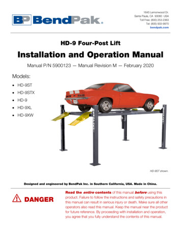
1645 Lemonwood Dr.Santa Paula, CA 93060 USAToll Free: (800) 253-2363Tel: (805) 933-9970bendpak.comHD-9 Four-Post LiftInstallation and Operation ManualManual P/N 5900123 — Manual Revision M — February 2020Models: HD-9ST HD-9STX HD-9 HD-9XL HD-9XWHD-9ST shown.Designed and engineered by BendPak Inc. in Southern California, USA. Made in China. DANGERRead the entire contents of this manual before using thisproduct. Failure to follow the instructions and safety precautions inthis manual can result in serious injury or death. Make sure all otheroperators also read this manual. Keep the manual near the productfor future reference. By proceeding with installation and operation,you agree that you fully understand the contents of this manual.
Manual. HD-9 Four-Post Lifts, Installation and Operation Manual, Manual P/N 5900123, Manual Revision M,Released February 2020.Copyright. Copyright 2020 by BendPak Inc. All rights reserved. You may make copies of this document if youagree that: you will give full attribution to BendPak Inc., you will not make changes to the content, you do not gainany rights to this content, and you will not use the copies for commercial purposes.Trademarks. BendPak and the BendPak logo are registered trademarks of BendPak Inc. All other company,product, and service names are used for identification only. All trademarks and registered trademarks mentionedin this manual are the property of their respective owners.Limitations. Every effort has been made to make sure complete and accurate instructions are included in thismanual. However, product updates, revisions, and/or changes may have occurred since this manual waspublished. BendPak reserves the right to change any information in this manual without incurring any obligation forequipment previously or subsequently sold. BendPak is not responsible for typographical errors in this manual.You can always find the latest version of the manual for your product on the BendPak website.Warranty. The BendPak warranty is more than a commitment to you: it is also a commitment to the value ofyour new product. Contact your nearest BendPak dealer or visit www.bendpak.com/support/warranty forfull warranty details. Go to bendpak.com/support/register-your-product/ and fill out the online form to registeryour product (be sure to click Submit).Safety. Your product was designed and manufactured with safety in mind. However, your safety also dependson proper training and thoughtful operation. Do not install, operate, maintain, or repair the unit without reading andunderstanding this manual and the labels on the unit; do not use your Lift unless you can do so safely!Owner Responsibility. In order to maintain your product properly and to ensure everyone’s safety, it is theresponsibility of the product owner to read and follow these instructions: Follow all installation, operation, and maintenance instructions. Make sure product installation conforms to all applicable local, state, and federal codes, rules, and regulations,such as state and federal OSHA regulations and electrical codes. Read and follow all safety instructions; keep them readily available for operators. Make sure all operators are properly trained, know how to safely operate the unit, and are properly supervised. Do not operate the product until you are certain that all parts are in place and operating correctly. Carefully inspect the product on a regular basis and perform all maintenance as specified. Service and maintain the unit with approved replacement parts only. Keep instructions permanently with the productand make sure all labels are clean and visible. Only use the Lift if it can be used safely!Unit Information. Enter the Model Number, SerialNumber, and the Date of Manufacture from the labelon your unit. This information is required for part orwarranty issues.Model:Serial:Date of Manufacture:
Table of ContentsIntroduction3Operation68Shipping Information4Maintenance71Safety Considerations4Troubleshooting73Components6Wiring Diagrams74Specifications8Labels76FAQs11Parts Drawings79Installation Checklist12ALI Store91Installation13IntroductionThis manual describes the following BendPak Four-Post Lifts: HD-9ST. Four-Post Lift with an overall width of 100.25" (8.4 feet), raising Vehicles up to 9,000 lbs(4,082 kg). ALI certified.HD-9STX. Has the same overall width as the HD-9ST but with higher rise and extendedlength. ALI certified.HD-9. Four-Post Lift with an overall width of 110.25" (9.2 feet), raising Vehicles up to 9,000 lbs(4,082 kg). ALI certified.HD-9XL. Has the same overall width as the HD-9, but with extended length. ALI certified.HD-9XW. Has the same overall width as the HD-9, but with higher rise and extendedlength. ALI certified.This manual is mandatory reading for all users of the HD-9 Series, including anyone who installs, uses,maintains, repairs, or wants to know more about them. DANGERUse care when installing, operating, maintaining, or repairing this equipment; failure todo so could result in property damage, product damage, injury, or (in very rare cases)death. Make sure only authorized personnel operate this equipment. All repairs mustbe performed by an authorized technician. Do not make modifications to the unit; thisvoids the warranty and increases the chances of injury or property damage. Makesure to read and follow the instructions in this manual and on the labels on the unit.Keep this manual on or near the equipment so that anyone who uses or services it can read it. If youare having issues, refer to the Troubleshooting section of this manual for assistance.Technical support and service is available from your dealer, on the Web at bendpak.com/support,by email at techsupport@bendpak.com, or by phone at (800) 253-2363, extension 196. Youmay also contact BendPak for parts replacement information at (800) 253-2363, extension 191;please have the model and serial number of your unit available.HD-9 Series Four-Post Lifts3P/N 5900123 — Rev. M — February 2020
Shipping InformationYour equipment was carefully checked before shipping. Nevertheless, you should thoroughly inspectthe shipment before you sign to acknowledge that you received it.When you sign a bill of lading, it tells the carrier that the items on the invoice were received in goodcondition. To protect yourself, do not sign until after you have inspected the shipment. If any ofthe items listed on the bill of lading are missing or are damaged, do not accept the shipment until thecarrier makes a notation on the bill of lading that lists the missing and/or damaged goods.If you discover missing or damaged goods after you receive the shipment and have signed the bill oflading, notify the carrier at once and request the carrier to make an inspection. If the carrier will notmake an inspection, prepare a signed statement to the effect that you have notified the carrier (on aspecific date) and that the carrier has failed to comply with your request.It is difficult to collect for loss or damage after you have given the carrier a signed bill of lading. If thishappens to you, file a claim with the carrier promptly. Support your claim with copies of the bill oflading, freight bill, invoice, and photographs, if available. Our willingness to assist in helpingyou process your claim does not make us responsible for collection of claims orreplacement of lost or damaged materials.Safety ConsiderationsRead this entire manual carefully before installing or using the product. Do notinstall or operate the product until you are familiar with all operating instructions and warnings. Do notallow anyone else to operate it until they are familiar with all operating instructions and warnings. Keepthis manual on or near the product for future reference.Read and follow the warnings and instructions on the labels on the product. Contact BendPak at(800) 253-2363 or techsupport@bendpak.com if you need replacement labels or areplacement manual.Safety InformationThe following safety information applies to the HD-9 Four-Post Lifts: BendPak recommends referring to the ANSI/ALI ALIS Standard (R2015) Safety Requirements forInstallation and Service for more information about safely installing, using, and servicing your Lift.The product may only be operated by authorized, trained persons.You must wear OSHA-approved (publication 3151) personal protective equipment at all timeswhen installing, using, maintaining, or repairing the Lift: leather gloves, steel-toed work boots, eyeprotection, back belts, and hearing protection are mandatory.Never exceed the rated capacity of the Lift.When the Lift is in use, keep all body parts well away from it.Do not make any modifications to the Lift; this voids the warranty and increases the chances ofinjury or property damage.Make sure all operators read and understand this Installation and Operation Manual. Keep themanual near the Lift at all times.Make an inspection of the Lift before using it. Check for damaged, worn, or missing parts. Do notuse it if you find any of these issues. Instead, take it out of service, then contact an authorizedrepair facility, your dealer, or BendPak at (800) 253-2363 or techsupport@bendpak.com.HD-9 Series Four-Post Lifts4P/N 5900123 — Rev. M — February 2020
BendPak recommends making a thorough inspection of the product at least once a year.Replace any damaged or severely worn parts, decals, or warning labels.SymbolsFollowing are the symbols used in this manual: DANGER WARNING CAUTIONNOTICETipCalls attention to an immediate hazard that will result in death or severe injury.Calls attention to a hazard or unsafe practice that could result in death or severepersonal injury.Calls attention to a hazard or unsafe practice that could result in minor personalinjury, product damage, or property damage.Calls attention to a situation that, if not avoided, could result in product or propertydamage.Calls attention to information that can help you use your product better.Liability InformationBendPak Inc. assumes no liability for damages resulting from: Use of the equipment for purposes other than those described in this manual. Modifications to the equipment without prior, written permission from BendPak. Injury or death caused by modifying, disabling, overriding or removing safety features. Damage to the equipment from external influences. Incorrect operation of the equipment.Electrical Information DANGERAll wiring must be performed by a licensed, certified Electrician. Do not performany maintenance until main electrical power has been disconnected from the Liftand cannot be re-energized until all procedures are complete.Important electrical information: Improper electrical installation can damage the Power Unit motor, which is not covered by thewarranty.The Lift uses electrical energy; if your organization has Lockout/Tagout policies, make sure toimplement them after connecting to a power source.Use a separate circuit breaker for each Power Unit.Protect each circuit with a time delay fuse or circuit breaker:- For a 208 to 230 VAC, single phase circuit, use a 25 amp fuse.- For a 208 to 230 VAC, three phase circuit, use a 20 amp fuse.- For a 380 to 440 VAC, three phase circuit, use a 15 amp fuse.HD-9 Series Four-Post Lifts5P/N 5900123 — Rev. M — February 2020
ComponentsThe main components of your Lift include: Power Post. The Post that holds the Power Unit. The Power Post can be in either of twolocations. You can tell the Power Post from the other Posts because it has two MountingBrackets on it. Mount the Power Unit on one of the two Mounting Brackets.The other three Posts. These Posts are interchangeable.Power Unit. An electric/hydraulic unit that connects to an electric power source and thenprovides Hydraulic Fluid to the Hydraulic Cylinder that raises and lowers the Runways.Powerside Runway. On the same side as the Power Post. The Powerside Runway has theHydraulic Cylinder and the Lifting Cables under them. The Powerside Runway must go next to thePower Post.Offside Runways. The other Runway. It does not have a Hydraulic Cylinder or Lifting Cablesunder.Utility Rails. Hold the optional Rolling Jacks. Utility Rails must go on the inside of the Lift.Crosstubes. Go at each end of the Lift. The Crosstubes are hollow; the Lifting Cables that raiseand lower the Runways are routed through the Crosstubes. The Crosstubes are notinterchangeable: Each Crosstube has an opening (called a ‘Window’) that faces the inside of theLift. Make sure to install the Lift so that the Windows open to the inside of the Liftonly.Drive-up Ramps. One for each Runway. Use them to drive onto and off of the Runways.Tire Stops. Located at the Front of the Lift, Tire Stops prevent the Vehicle’s Front Tires fromgoing any further forward. Additionally, we strongly recommend chocking the Vehicle’s Rear Tires.Safety Locks. Once engaged, they hold the Runways in position, even if the power goes out orthere is a leak in the Hydraulic Hoses. Your Lift has a column of Safety Locks in each post, spacedevery four inches. This lets you lock the Runways at just the right height for what you want to do.This Lift also has a backup Slack Safety system; refer to About Safety Locks for moreinformation. Only leave the Runways on the ground or engaged on a Safety Lock.Pushbutton Air Valve. Includes a Pushbutton that moves the Safety Locks away from theLadder so that they do not engage as you lower the Runways. Used only to lower the Runways.Usually located next to the Power Post.Ladders. Pieces of steel that gets installed at the back of each Post; these are part of the SafetyLock system.HD-9 Series Four-Post Lifts6P/N 5900123 — Rev. M — February 2020
Drawing shows the two possible Power Post locations; only one Post has the Brackets for mountingthe Power Unit. Not all components are shown.Optional AccessoriesThere are additional products you can use with your Lift: Aluminum Drive-up Ramps. The Aluminum Drive-up Ramps are a low-profile alternative to thestandard Drive-up Ramps that come with your Lift. See the Aluminum Approach Rampspage on the BendPak website for more information.Aluminum Platforms. Aluminum Platforms fill in the open space between the Lift’s twoRunways, preventing liquids from dripping on the floor or onto a Vehicle below the Runways. Seethe Aluminum Platforms page on the BendPak website for more information.Caster Kit. The Caster Kit allows you to pick up and move your Lift without needing todisassemble it. See the Caster Kit page on the BendPak website for more information.Plastic Drip Trays. Plastic Drip Trays prevent liquids from falling onto your work area or Vehicle.See the Plastic Drip Trays page on the BendPak website for more information.Rolling Bridge Jack. A Rolling Bridge Jack raises the wheels of a Vehicle off the Runways of aLift, making it much easier to perform service such as brake jobs and suspension work while theVehicle is still on the Lift. See the RBJ4500 Rolling Bridge Jack page on the BendPakwebsite for more information.HD-9 Series Four-Post Lifts7P/N 5900123 — Rev. M — February 2020
SpecificationsHD-9 Series Four-Post Lifts8P/N 5900123 — Rev. M — February 2020
ModelHD-9STHD-9STXLifting Capacity9,000 lbs / 4,082 kgMax capacity at Front Axle4,500 lbs / 2,041 kgMax capacity at Rear Axle4,500 lbs / 2,041 kg5" / 125 mma Min. runway heightb Maximum rise70" (5.10 feet) / 1,778 mm82" (6.10 feet) / 2,083 mmc Maximum lifting height75" (6.3 feet) / 1,903 mm87" (7.3 feet) / 2,208 mm100.25" (8.4 feet) / 2,546 mmd Overall widthe Outside length174" (14.6 feet) / 4,420 mm198" (16.6 feet) / 5,029 mmf Overall length200.5" (16.9 feet) / 5,094 mm224.5" (18.9 feet) / 5,704 mmg Height of post88" (7.4 feet) / 2,235 mm100" (8.4 feet) / 2,540 mm90" (7.6 feet) / 2,292 mmh Distance between posts76.5" (6.5 feet) / 1,943 mmi Drive-thru clearance19" / 482 mmj Runway width164.5" (13.9 feet) / 4,178 mmk Runway length188.5" (15.9 feet) / 4,788 mm38" (3.2 feet) / 963 mml Width between runwaysm Runway centerline56.5" (4.9 feet) / 1,435 mmn Outside edge of runways75.5" (6.4 feet) / 1,918 mm115" (9.7 feet) / 2,921 mm135" (11.3 feet) / 3,429 mmMin. wheelbase @ 75 capacity1100" (8.4 feet) / 2,540 mm115" (9.7 feet) / 2,921 mmMin. wheelbase @ 50 capacity85" (7.1 feet) / 2,159 mm95" (7.11 feet) / 2,413 mmMin. wheelbase @ 25 capacity170" (5.10 feet) / 1,778 mm80" (6.8 feet) / 2,032 mmSafety Lock positions14, spaced every 4" / 102 mm17, spaced every 4" / 102 mmMin. wheelbase @ ratedcapacity11Lifting timeMotor45 – 50 seconds60 Hz, 1 Ph (special voltages available upon request)The Lift supports less weight than its rated capacity if the Vehicle’s wheelbase is shorter; this isbecause the wheels are closer to the middle of the Runways, where there is less strength.For example, the maximum weight allowed on the Lift for a Vehicle with a wheelbase of 85" is50 percent of the Lift’s rated capacity (or 4,500 lbs when the rated capacity is 9,000 lbs).Specifications subject to change without notice.1HD-9 Series Four-Post Lifts9P/N 5900123 — Rev. M — February 2020
ModelHD-9HD-9XLLifting capacityMax capacity at Front AxleMax capacity at Rear Axle9,000 lbs / 4,082 kg4,500 lbs / 2,041 kg4,500 lbs / 2,041 kga Min. runway heightb Maximum rise70" (5.10 feet) / 1,778 mmc Maximum lifting height75" (6.3 feet) / 1,903 mm4.5" / 114 mmd Overall widthe Outside lengthf Overall lengthg Height of posth Distance between postsi Drive-thru clearancej Runway widthk Runway lengthMin. wheelbase @ 50 capacity 1Min. wheelbase @ 25 capacity 1Locking positionsMotor182" (6.10 feet) /2,083 mm87" (7.3 feet) /2,208 mm110.25" (9.2 feet) / 2,800 mm174" (14.6 feet) /4,420 mm200" (16.8 feet) /5,080 mm198" (16.6 feet) / 5,029 mm224" (18.8 feet) / 5,690 mm88" (7.4 feet) / 2,235 mm100" (8.4 feet) /2,540 mm100.25" (8.4 feet) / 2,555 mm86.5" (7.3 feet) / 2,197 mm19" / 482 mm164.5" (13.9 feet) /4,178 mml Width between runwaysm Runway centerlinen Outside edge of runwaysMin. wheelbase @ ratedcapacity 1Min. wheelbase @ 75 capacity 1HD-9XW188.5" (15.9 feet) / 4,788 mm38" / 963 mm or 44.25" / 1,127 mm56.5" – 63.25" / 1,435 – 1,610 mm75.5" – 82.25" / 1,918 – 2,092 mm115" (9.7 feet) /135" (11.3 feet) / 3,429mm2,921 mm100" (8.4 feet) /115" (9.7 feet) / 2,921 mm2,540 mm85" (7.1 feet) /95" (7.11 feet) / 2,413 mm2,159 mm70" (5.10 feet) /80" (6.8 feet) / 2,032 mm1,778 mm14, spaced every 4" / 14; spaced every 4" /17; spaced every 4" /102 mm102 mm102 mm220 VAC, 60 Hz, 1 Ph (special voltages available upon request)The Lift supports less weight than its rated capacity if the Vehicle’s wheelbase is shorter; this isbecause the wheels are closer to the middle of the Runways, where there is less strength. Forexample, the maximum weight allowed on the Lift for a Vehicle with a wheelbase of 85" is 50percent of the Lift’s rated capacity (or 4,500 lbs when the rated capacity is 9,000 lbs).Specifications subject to change without notice.HD-9 Series Four-Post Lifts10P/N 5900123 — Rev. M — February 2020
Frequently Asked QuestionsQuestion:Answer:What kinds of Vehicles can I put on my Lift?Cars, trucks, SUVs; anything that fits on the Runways, up to 9,000 lbs (4,082 kg).Q: Can any of the four Posts be the ‘Power Post’?A: No; the only two possible locations for the Power Post are either the Front Driver-Side or the RearPassenger-Side. This will be explained later.Q: How can my Lift fit both narrow and wide Vehicles on the Runways?A: The Offside Runway (the Runway without the Hydraulic Cylinder or Lifting Cables underneath) canbe easily switched between the narrow and wide settings. You would need to unbolt the OffsideRunway on both ends, slide it over to the other position, and then bolt it into position. Theadjustable Offside Runway does not apply to the HD-9ST or HD-9STX models.Q: Does the Lift have to be anchored in place?A: Yes, BendPak strongly recommends that you anchor the Lift; it may be less stable if you do notanchor the Bases, and you could possibly void ALI certification. If you plan to use the optionalRolling Bridge Jack, the Lift must be anchored.Q: How high does the ceiling have to be?A: It depends on the height of the Vehicles you are putting on the Runways and how high you raisethe Runways. If you are going to put a tall Vehicle on the Lift and raise it all the way up, you shouldcheck to make sure there is enough room.Q: Does it matter if I drive my Vehicles in front first or back them in?A: We strongly recommend driving your Vehicle in front first, because that makes it easier to centerthe wheels on the Runways. Also, remember to put the front wheels up against the Tire Stopsand chock the rear wheels.Q: Will the Lifting Cables really hold my Vehicles?A: Yes. Your Lift has 4/10 inch thick, aircraft-quality wire rope that runs through oversized Sheaves,reducing friction on them and extending their life with minimal maintenance.Q: How many Safety Locks does my Lift have?A: Depending on the Lift model you have, your Lift has either 14 or 17 Safety Locks for you to use.See Specifications for more information about your Lift model.Q: How long can I leave a Vehicle on a raised Runway?A: As long as you want, if it is on a Safety Lock. Once the Lift is engaged on a Safety Lock,gravity holds it in position, so a loss of power does not impact it; it is going to stay where you leftit. Always leave the Runways either fully lowered or engaged on a Safety Lock.Q: Can I install my Lift outside?A: Your Lift is approved for indoor installation and use only. Outdoor installation is prohibited.Q: How many Rolling Bridge Jacks can I use on my Four Post Lift?A: Two. Never place the Rolling Bridge Jack towards the middle of the Runways, they must go atthe Front or Rear of the Lift.HD-9 Series Four-Post Lifts11P/N 5900123 — Rev. M — February 2020
Installation ChecklistFollowing are the steps needed to install your Lift. Perform them in the order shown. 1. Review the safety rules. 2. Make sure you have the necessary tools. 3. Plan for Electrical work. 4. Select the installation location. 5. Check the Clearances. 6. Decide the Lift Orientation. 7. Unload and unpack the Lift components. 8. Create Chalk Line Guides. 9. Move the Posts into position. 10. Install the Crosstubes. 11. About Safety Locks. 12. Install the Ladders and Top Caps. 13. Raise the Crosstubes. 14. Secure the Ladders. 15. Removing the Sheaves. 16. Install the Runways. 17. Route the Lifting Cables. 18. Working with Compression Fittings and Tubing. 19. Install the Air Line. 20. Install the Return Line. 21. About Hydraulic Contamination. 22. Install the Hydraulic Hose. 23. Install the Power Unit. 24. Install the Flex Tube Bracket Plate and Angle Plate. 25. Install the Flex Tube. 26. Install the Pushbutton Air Valve and connect the Air Lines. 27. Connect the Return Line. 28. Connect the Hydraulic Hose. 29. Contact the Electrician. 30. Connect to a power source (Electrician required). 31. Install the Power Disconnect Switch and Thermal Disconnect Switch (Electrician required). 32. About Effective Embedment. 33. Anchor the Posts. 34. Perform final leveling. 35. Install the Accessories. 36. Lubricate the Lift. 37. Test the Lift. 38. Review the final checklist. 39. Outdoor usage.HD-9 Series Four-Post Lifts12P/N 5900123 — Rev. M — February 2020
InstallationThe installation process takes multiple steps. Perform them in the order listed.Read the entire Installation section before beginning the install; this gives you a betterunderstanding of the process as a whole. WARNINGOnly use the factory-supplied parts that came with your Lift. If you useparts from a different source, you void your warranty and compromise the safety ofeveryone who installs or uses the Lift. If you are missing parts, visitbendpak.com/support or call (800) 253-2363, extension 191.Being SafeWhile installing this equipment, your safety depends on proper training and thoughtful operation. WARNINGDo not install this equipment unless you have automotive Lift installation training.Always use proper lifting tools, such as a Forklift or Shop Crane, to move heavycomponents. Do not install this equipment without reading and understanding thismanual and the safety labels on the unit.Only fully trained personnel should be involved in installing this equipment. Pay attention at all times.Use appropriate tools and lifting equipment. Stay clear of moving parts.BendPak recommends referring to the current version of the ANSI/ALI ALIS Standard SafetyRequirements for Installation and Service for more information about safely installing, using, andservicing your Lift. WARNINGYou must wear OSHA-approved (publication 3151) personal protective equipmentat all times when installing, using, maintaining, or repairing the Lift: leather gloves,steel-toed work boots, eye protection, back belts, and hearing protection aremandatory.Using ToolsYou may need some or all of the following tools: Rotary hammer drill or similar ¾ inch carbide bit (conforming to ANSI B212.15) Hammer, crow bar, and two sawhorses Four-foot level and 12-foot ladder Open-end wrench set, SAE and metric Socket and ratchet set, SAE and metric Hex key wrench set Medium crescent wrench, torque wrench, pipe wrench Chalk line Medium-sized flat screwdriver and needle-nose pliers Tape measure (25 feet or above) Forklift, Shop Crane, or heavy-duty rolling dollyHD-9 Series Four-Post Lifts13P/N 5900123 — Rev. M — February 2020
Planning for Electrical WorkYou will need to have a licensed, certified Electrician available at some point in the installation. DANGERAll wiring must be performed by a licensed, certified Electrician.Notify your Electrician in advance so that they come prepared with an appropriate Power Cord with aPlug for connecting to the power source, a Power Disconnect Switch, and a Thermal DisconnectSwitch. Refer to Contacting the Electrician for more information.Your Electrician needs to: Connect the Power Unit to an electric power source. An electric power source isrequired. The Power Unit comes with a pigtail for wiring to a power source. Have your Electricianremove the pigtail and wire from inside the Electrical Box on the Power Unit to a Power Cord andPlug or have them wire it directly into the electrical system at the Lift location.Note: Installing the Power Unit and connecting the Power Unit to the power source areseparate procedures and are completed at different times in the installation process. Youdo not need an Electrician to install the Power Unit, but an Electrician is required toconnect the Power Unit to the power source.Install a Power Disconnect Switch. Ensures you can quickly and completely interruptelectrical power to the Lift in the event of an electrical circuit fault, emergency situation, or whenequipment is undergoing service or maintenance. Put it within sight and reach of the Lift operator.Install a Thermal Disconnect Switch. Ensures the equipment shuts down in the event of anoverload or an overheated motor.Note:None of these components are included with the Lift.HD-9 Series Four-Post Lifts14P/N 5900123 — Rev. M — February 2020
Selecting a LocationWhen selecting the location for your Lift, consider: Architectural plans. Consult the architectural plans for your desired installation location. Makesure there are no issues between what you want to do and what the plans show.Available space. Make sure there is enough space for the Lift: front, back, sides, and above.Refer to Specifications for measurements.Overhead Clearance. Check for overhead obstructions such as building supports, heaters,electrical lines, low ceilings, hanging lights, and so on. Use the maximum lifting height of your Liftmodel plus the height of the tallest Vehicle you plan on raising to determine how much height youwill need at the Lift location.Power. You need an appropriate power source for the Power Unit.Outdoor installations. Your Lift is approved for indoor installation and use only.Floor. Only install the Lift on a flat, concrete floor; do not install on asphalt or any other surface.The surface must be level; do not install if the surface has more than three degrees of slope. WARNING Shimming. If your concrete floor is not completely level, you can use Shims under the bases ofthe Posts, as needed, to level the Lift. To estimate your Shim requirements, use a transit level andtargets to check for flatness. Use the provided Shims as necessary.NOTICE Installing your Lift on a surface with more than three degrees of slope could lead toinjury or even death; only install the Lift on a level floor. If your floor is not level,consider making the floor level or using a different location.Do not shim a Post more than half an inch using the provided Shims and AnchorBolts. A maximum shim of 2 inches is possible by ordering optional Shim Plates.Contact BendPak at (800) 253-2363, extension 191 to order.Concrete specifications. Do not install the Lift within 6 inches of cracked or defectiveconcrete. Make sure the concrete is at least 4.25 inches thick, 3,000 PSI, and cured for aminimum of 28 days. CAUTIONBendPak lifts are supplied with installation instructions and Concrete anchors thatmeet the criteria set by the current version of the American National Standard“Automotive Lifts – Safety Requirements for Construction, Testing, and Validation”,ANSI/ALI ALCTV. You are responsible for any special regional structural and/orseismic anchoring requirements specified by any other agencies and/or codes suchas the Uniform Building Code (UBC) and/or International Building Code (IBC).Be sure to check your floor for the possibility of it being a post-tension slab. In this case, youmust contact the building architect before drilling. Using ground penetrating radar may help youfind the tensioned steel. WARNING Cutting through a tensioned Cable can result in injury or death. Do not drill into apost-tension slab unless the building architect confirms you are not going to h
implement them after connecting to a power source. Use a separate circuit breaker for each Power Unit. Protect each circuit with a time delay fuse or circuit breaker: - For a 208 to 230 VAC, single phase circuit, use a 25 amp fuse. - For a 208 to 230 VAC, three phase circuit, use a 20 amp fuse.