Transcription
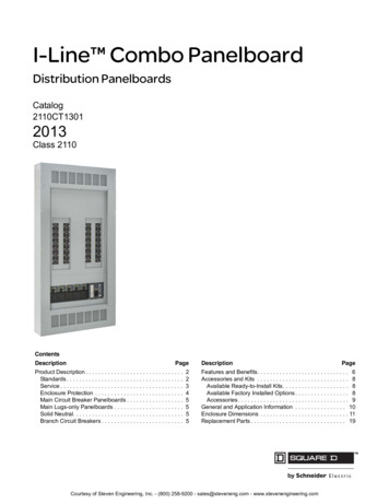
I-Line Circuit BreakerPanelboardsCatalog2110CT9701R07/192019Class 2110CONTENTSDescription . . . . . . . . . . . . . . . . . . . . . . . . . . . . . . . . . . . . . . . . . . . . PageProduct Description . . . . . . . . . . . . . . . . . . . . . . . . . . . . . . . . . . . . Page 2Features and Benefits . . . . . . . . . . . . . . . . . . . . . . . . . . . . . . . . . . Page 6Accessories . . . . . . . . . . . . . . . . . . . . . . . . . . . . . . . . . . . . . . . . . . Page 7General and Application Information . . . . . . . . . . . . . . . . . . . . . . . Page 8Dimensions. . . . . . . . . . . . . . . . . . . . . . . . . . . . . . . . . . . . . . . . . . Page 13
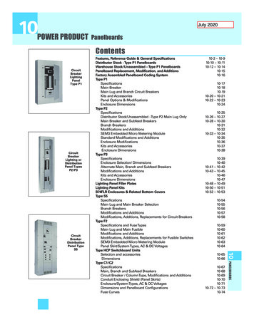
I-Line Circuit Breaker PanelboardsProduct DescriptionProduct DescriptionSquare D -brand I-Line circuit breaker power distribution panelboardsare for use on AC or DC systems. The panels, labeled cULus (complianceto UL and CSA standards certified by UL) are also UnderwritersLaboratories (UL ) Listed under File E33139. The following are suitable foruse as service entrance equipment: All main circuit breaker panelboards. All main lugs panelboards with six disconnects or less. All main lugs panelboards with branch-mounted, back-fed maincircuit breaker. (For Canadian MLO service entrance, use HCP-SU andHCR-U only).A solid neutral that is insulated, but may be bonded to the box with agrounding strap.Service entrance panelboards meeting the requirements of CSA areavailable in Canada factory-assembled only.I-Line circuit breaker panelboards are available as 400–1200 A main lugsonly and 100–1200 A main circuit breakers. I-Line panelboards aredesigned to accept the following circuit breakers: FA, FH, BD, BG, BJ, BK,HD, HG, HJ, HL, HR, QB, QD, QG, QJ, JD, JG, JJ, JL, JR, LA, LD, LG, LJ,LH, LL, LR, MG, MJ, PG, PJ, PK, PL, RG, RJ, RK, and RL.StandardsType HCR-U—1200 A Main Circuit BeakerI-Line circuit breaker panelboards are designed, manufactured, and testedto comply with the following standards:StandardDescriptionUL 50Standard for enclosures for electrical equipmentUL 67Standard for panelboardsCSA C22.2, Nos. 29 and 94—1989Standard for panelboards and enclosed panelboardsNFPA 70National Electrical Code (NEC)NEMA PB 1Standard for panelboardsW–P 115C Type 1 Class 1Specification for circuit breaker panelboards2000 IBCUS standard for seismic requirements1995 NBCCCanadian standard for seismic requirementsServiceI-Line circuit breaker panelboards can be used on the following systemvoltages:Type HCR-U—1200 A Main Circuit Beaker 120/240 VAC; 1-phase, 3-wire240 VAC; 1-phase, 2-wire240 VAC; 3-phase, 3-wire240 VAC Ground, B-phase; 3-phase, 3-wire208Y/120 VAC; 3-phase, 4-wire480Y/277 VAC; 3-phase, 4-wire480 VAC; 3-phase, 3-wire600Y/347 VAC; 3-phase, 4-wire600 VAC; 3-phase, 3-wire125/250 VDC; 3-wire250 VDC; 2-wire2 1998–2019 Schneider ElectricAll Rights Reserved07/2019
I-Line Circuit Breaker PanelboardsProduct DescriptionPanelboard TypesPanelboardTypeMaximum MainsAmpacityMainCircuitBreakersMain LugsMaximumBranch CircuitBreaker FrameSize aLeftRightEnclosureDimensions bWidth#IN Depth#IN(mm)(mm)HCJ800 A800 AJDJD32 (813)9.50 (241)HCP-SU800 A800 A cMG, PGNone26 (600)9.50 (241)HCP1200 A800 A cMG, PGJD42 (1067)9.50 (241)HCR-U1200 A1200 A cRGJD44 (1118)9.50 (241)a For a complete listing of applicable circuit breaker types, refer to the dimensions section.bRefer to the Dimensions section for standard panelboard heights.c Available as a main circuit breaker panelboard when provided with a branch mounted back-fedmain circuit breaker.Type HCP—600 A Main Circuit BreakerType HCP-SU800 A Main Circuit BeakerType HCJ—400 A Main Lugs307/2019 1998–2019 Schneider ElectricAll Rights Reserved
I-Line Circuit Breaker PanelboardsProduct DescriptionEnclosure TypesTypesEnvironmentsProvides Protection AgainstType 1IndoorContact with the enclosed equipmentType 2IndoorFalling water and dirtType 3ROutdoorFalling rain, sleet; undamaged by iceType 4/4X Stainless Indoor/OutdoorCorrosion, hose-directed water, dustType 5IndoorSettling dust, falling dirt, dripping liquidsType 12IndoorCirculating dust, falling dirt, dripping liquidsHCJ, HCP, HCP-SU, and HCR-U surface and flush trims available asfour-piece construction, standard (door not included). An optional fourpiece trim with door is also available.Fronts:Type 1EnclosuresFinished with gray-baked enamel electrodeposited over cleanedphosphatized steel (ANSI 49).Directory card holders provided with all fronts.Types 1 and 2 Enclosure with Optional DoorBoxes:Galvanized steel in 26, 32, 42, and 44-inch (660, 813, 1067, and 1118mm) widths.Removable endwalls without knockouts.Gasketed door with vault handle and directory card holder.Three-point latching.Type 3R, 5,and 12EnclosuresFlush Lock used onHCJ, and HCP-SU Types1 and 2 Fronts(Catalog No. PK4FL)Sliding Vault Lock used onHCP, and HCR-U Types 1and 2 Fronts(Catalog No. PK5FL)End and side gutter trim.No knockouts.Removable drain screw for Type 3R.Finished with gray-baked enamel electrodeposited over cleaned phosphatizedsteel (ANSI 49).Type ant, stainless steel.Watertight and dusttight.Gasketed door.Directory card located on inside of door.Type 3R, 5, and 12 EnclosuresVault Handle used on allType 3R, 5, and 12 Enclosures(Catalog No. PK4NVL)Type 3R, 5, and 12 Enclosures407/2019 1998–2019 Schneider ElectricAll Rights Reserved
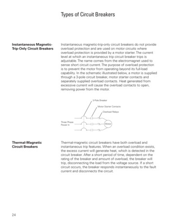
I-Line Circuit Breaker PanelboardsProduct DescriptionMain Breaker PanelboardsMain Circuit Breaker and Solid Neutral Compartment(Canada service entrance not shown) Accept a maximum 1200 A, 80% or 100% rated main breaker. Suitable for use as service entrance equipment with appropriatebarriers, US and Canada. Accepts mechanically restrained I-Line circuit breakers.Available factory-assembled or merchandised.*Factory-assembled main circuit breaker interiors are availablebottom-feed or top-feed.Available with a short circuit current rating (SCCR) up to 200 kAmaximum (100 kA @ 600 VAC) when supplied by an I-Limiter circuit breaker. Available with a silver-plated or tin-plated copper bus, or tin-platedaluminum bus. Solid neutral is mounted in the mains compartment with the maincircuit breaker. Merchandised panelboards are provided as bottom-feed.Main Lugs Only PanelboardsMain Lug and Solid Neutral CompartmentMain neutral lug Available with main lug only interiors rated up to 1200 A. Accepts mechanically restrained I-Line circuit breakers. Available with a silver-plated or tin-plated copper bus, or tin-platedaluminum bus. Solid neutral is mounted in the mains compartment with the main lugs.Available factory-assembled or merchandised.Suitable for use as service entrance equipment when provided with amain circuit breaker, US and Canada.Available with a short circuit current rating (SCCR) up to 200 kAmaximum (100 kA @ 600 VAC) when supplied by an I-Limiter circuitbreaker.Hinged cover, isolated main lugs compartment.Main lug interiors are available as top-feed or bottom-feed.Solid NeutralFull capacity bondingstrap for use on serviceentrance applicationsTypical Solid Neutral Mounts in main lug or main circuit breaker compartment.Does not take up interior circuit breaker mounting space.UL/CSA Listed for use with Al or Cu conductors.Copper or aluminum neutral available.200% rated neutral available as a factory-assembled option.Neutral with C/T for Use on HCR-U When Ground-FaultProtection is Required (Catalog No. HCR12SNCT)5 1998–2019 Schneider ElectricAll Rights Reserved07/2019
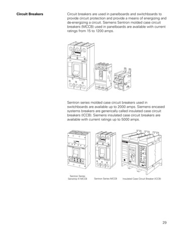
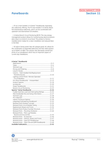
I-Line Circuit Breaker PanelboardsFeatures and BenefitsFeatures and BenefitsFeatured below are just a few of the many features and benefits ofSquare D -brand I-Line circuit breaker panelboards.Circuit BreakersI-Line circuit breakers, with their exclusive bus connection design, providesuperior reliability and performance advantages.Circuit Breaker Mounting 15–1200 A frame circuit breakers require only a screwdriver and arefirmly attached to the bus stack and mechanically attached to the interiorassembly. The connectors are an integral part of the I-Line circuit breaker—eliminating the assembly of connectors to the bus bar. Pre-assembled hardware means reduced installation time.The unique line side connection requires no routine maintenance.Steel channels provideadditional support for insulatorbracing structure.Ratchet-Type MountingBus phase insulators interlockwith the circuit breakerinsulating shroud and providehigh dielectric strengthbetween the bus bars.Circuit breakers on righthand side of the busstructure are completelyindependent of positionand frame size of thoseon left-hand side.Circuit breakermountingbracket—anintegral part ofeach circuitbreaker; securelysupports andaligns load end ofcircuit breaker.Circuit breaker connectors areshrouded and braced in moldedprotective insulator. Circuit breakerjaws are lubricated and pre-set at thefactory and require no adjustment.Insulating shroud keysinto slots in bussupport base. Alignsand supports line endof circuit breaker.Glass-reinforcedpolyester insulatorsprovide continuousbus bar support.I-Line Bus Structure and Circuit Breaker MountingPush-to-TripPush-to-trip is a standard feature on all I-Line circuit breakers. It is useful forchecking circuit breaker operation and for testing auxiliary devices. Thecircuit breaker is mechanically tripped by pressing the push-to-trip button inthe circuit breaker case.Blow-On ConnectionsBlow-On ConnectionsAll circuit breaker connections are “blow-on” type. Under high-level shortcircuit conditions, the magnetic forces developed tend to draw the connectorjaws together, gripping the I-Line bus bar more firmly.607/2019 1998–2019 Schneider ElectricAll Rights Reserved
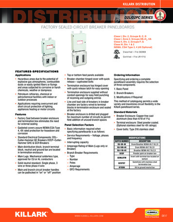
I-Line Circuit Breaker PanelboardsAccessoriesShort Circuit Current Rating (SCCR) SCCR is equal to the lowest interrupting capacity of a branch or maincircuit breaker installed in the panelboard. I-Line panelboards, with branch circuit breakers installed, areshort-circuit tested as complete units. All tests are conducted in accordance with UL 67 and CSA C22.2(Standards for Panelboards).With I-Limiter main circuit breaker, I-Line main circuit breaker panelboardsare UL/CSA Listed for use on systems with up to a 200,000 maximum RMSsymmetrical amperes available fault current (100 kA @ 600 VAC).I-Line Plug-on Unit with Surgelogic SPD SPD requires no wiring or conduit, saving labor time and materials.Bus-connected design enhances performance.Meets the requirements of UL and CSA for retrofit applications inexisting I-Line panelboards and switchboards. Integrated and circuit breaker disconnects feature compact design,requiring only 13.50 inches (343 mm) of branch mounting space. SCCR up to 200 kA rating (100 kA @ 600 VAC) meets a wide variety ofcustomer applications.AccessoriesI-Line Plug-On Unit with Surgelogic SPDA wide variety of accessories are available for field or factory installation ofI-Line panelboards.Equipment Ground BarsEquipment ground bars mount in the panelboard box to provide convenienttermination of equipment grounding conductors. They are available incopper or aluminum.Box ExtensionsEquipment Ground Bar (Catalog No. PK32DGTA)Box extensions provide additional end gutter for feeding cables into the endof the cabinet; they are UL/CSA Listed.Blank FillersBlank fillers are required to cover unused mounting space in I-Linepanelboards.Backfed Main Breaker BarriersTypical Box ExtensionsPrimarily for use in Canada, these barriers provide additional protection forbackfed main breakers.Blank Fillers (Catalog Nos. HNM4BL and HNM1BL)7 1998–2019 Schneider ElectricAll Rights Reserved07/2019
I-Line Circuit Breaker PanelboardsGeneral and Application InformationGeneral and Application InformationPlease refer to Digest Section 9 for circuit breaker ratings information.Circuit BreakerFrame TypeFA 240 VMaximumVoltageRating240277FA 480 V480277FH aNumber ofPoles231231Cont.AmpereRating15–100UL/CSA Interrupting Rating—RMS Amperes (Symmetrical)AC Volts, 50/60 HzDC Volts12024048060012525010 K25 K———5K25 K25 K18 K—10 K10 K25 K—10 K—35–10015–10015–3035–10065 K65 K c25 K c6002, 315–100———18 K—50 KBD600 Y1, 2, 315–12525 K25 K18 K14 K——BG600 Y1, 2, 315–12565 K65 K35 K18 K——BJ600 Y1, 2, 315–125100 K100 K65 K25 K——BK600 Y1, 215–30100 K100 K65 K65 K——HD6002, 315–15025 K25 K18 K14 K20 K20 KHG6002, 315–15065 K65 K35 K18 K20 K20 KHJ6002, 315–150100 K100 K65 K25 K20 K20 KHL6002, 315–150125 K125 K100 K50 K20 K20 KHR600315–150200 K200 K200 K100 K——QB2402, 370–22510 K10 K————QD2402, 370–22525 K25 K————QG2402, 370–22565 K65 K————QJ e2402, 370–225100 K100 K————JD6002, 3150–25025 K25 K18 K14 K20 K20 KJG6002, 3150–25065 K65 K35 K18 K20 K20 KJJ6002, 3150–250100 K100 K65 K25 K20 K20 KJL6002, 3150–250125 K125 K100 K50 K20 K20 KJR6002, 3150–250200 K200 K200 K100 K——LA6002, 3125–40042 K42 K30 K22 K10 K10 KLH a6002, 3125–40065 K65 K35 K25 K—50 KLD6002, 3250–60025 K25 K18 K14 K——LG6002, 3250–60065 K65 K35 K18 K—20 KLJ6002, 3250–600100 K100 K65 K25 K——LL6002, 3250–600125 K125 K100 K50 K—20 KLR6002, 3250–600200 K200 K200 K100 K——MG6002, 3300–80065 K65 K35 K18 K——MJ6002, 3300–800100 K100 K65 K25 K——PG6002, 3600–120065 K65 K35 K18 K——PJ6002, 3600–1200100 K100 K65 K25 K——PK d6002, 3600–120065 K65 K50 K50 K——PL4802, 3600–1200125 K125 K100 K25 K——Continued on next page807/2019 1998–2019 Schneider ElectricAll Rights Reserved
I-Line Circuit Breaker PanelboardsGeneral and Application InformationUL/CSA Interrupting Rating—RMS Amperes Number ofPolesRG6002, 31000–1200RJ6002, 31000–1200RK d6002, 31000–120065 K65 K65 K65 K——RL6002, 31000–1200125 K125 K100 K50 K——Circuit BreakerFrame TypeAC Volts, 50/60 Hz120DC Volts24048060012525065 K65 K35 K18 K——100 K100 K65 K25 K——‡ 15 and 20 A are Switching Duty rated (SWD).c 277 VAC rated.a Separate UL rating available for 240 V and 480 V grounded B phase systems. Circuit breakers must be ordered with 5861 suffix.c FG and FJ 600Y/347 VAC @ 15–30 A only.d Canada Only.eQJ 3-pole is rated 100 KA@208Y/120 VAC.Circuit Breaker Terminal DataCircuit BreakerFrame SizeAmpere RatingTerminal Lug Wire SizeFA100 A15–30#14-#4 Cu or #12-#4 AlFA100 A35–100#14-1/0 Cu or #12-1/0 AlFH100 A15–30#14-#4 Cu or #12-#4 AlFH100 A35–100#14-1/0 Cu or #12-1/0 AlBD, BG, BJ125 A15–125#14–2/0 Al/CuBK125 A15–30#14–2/0 Al/CuHD, HG, HJ, HL, HR150 A15–150#14-3/0 Al/CuQB, QB, QG, QJ225 A70–225#4-300 kcmil Al/CuJD, JG, JJ, JL250 A150–175#4/0 Al/CuJD, JG, JJ, JL, JR250 A200–250#3/0-350 kcmil Al/Cu(1) #1-600 kcmil or(2) #1-250 kcmil Al/CuLA, LH400 A125–400LD, LG, LJ, LL, LR400 A250LD, LG, LJ, LL, LR600 A400–600(2) #2-500kcmil AL/CUMG, MJ800 A300–800(3) 3/0-500 kcmil Al/CuPG, PJ, PKd, PL1200 A250–800(3) 3/0-500 kcmil Al/CuPG, PJ, PKd, PL1200 A1000–1200(4) 3/0-500 kcmil Al/CuRG, RJ, RKd, RL1200 A1000–1200(4) 3/0-600 kcmil Al/Cu(1) #2-600 kcmil CU or (1) #2-500 kcmil ALNOTE: Lugs are rated for 75 C wire, except FA (15–30 A) and FI (20–30 A), which are rated for 60/75 C. Torque values are listedon the circuit breaker faceplate tables.d Canada only.Circuit Breaker Accessories Shunt tripUndervoltage tripAlarm switchAuxiliary contactsGround-fault shunt trip9 1998–2019 Schneider ElectricAll Rights Reserved07/2019
I-Line Circuit Breaker PanelboardsGeneral and Application InformationNOTE: All accessories, except for the Ground-fault shunt trip arefield-installable for LA, LH circuit breakers.For detailed information on circuit breakers and accessories, refer to theDigest.10A20Circuit BreakerClassHD, HG, HJ, HL611QB, QD, QG, QJ734JD, JG, JJ, JL611LA, LH660MG, MJ612PG, PJ, PKd, PL612RG, RJ, RKd, RL612d Canada only.0A80Plug-On Lugs Terminal Data0A405A22Amperage RatingFrame SizeCatalogNo.250 A250 ASL250Plug-On LugsTerminal Lug Wire Size(1) #4-300 kcmil Al/Cu(1) #1-600 kcmil Al/Cu or400 A400 ASL400800 A800 ASL800M5(3) 3/0 AWG-500 kcmil1200 A1200 ASL1200P5(4) 3/0 AWG-500 kcmil1200 A1200 ASL1200P6(3) 350-600 kcmil(2) #1-250 kcmil Al/Cu1200 A1200 ASL1200P7(3) 3/0 AWG-750 kcmil(750 kcmil: Compact Al only)1200 A ‡1200 AS33930(4) 3/0-600 kcmil Al/Cu‡ For 100% rated applications (“R” frame breakers).Plug-On QO Distribution Panel (Catalog No. HQO306)1-Pole2-Pole3-PoleQO with Visi-Trip Indicator Six-pole, 240 VAC maximum Mounts in all I-Line panelboards.Use with QO, QO-H, QO-VH, QH, and Qwik-Gard plug-on circuitbreakers through 30 A. For detailed information, refer to DP CatalogClass 730 and 910.QO Distribution Panel Branch Circuit BreakersDistribution Channel TypeNumber of Poles & Amperages1-Pole 10–30 A10 k AIR, QO2-Pole 10–30 A3-Pole 10–30 A1-Pole 15–30 A ‡10 k AIR, QO-GFI2-Pole 15–30 A ‡1-Pole 15–30 AQwik-Gard Circuit Breaker with Ground FaultCircuit Interrupter22 k AIR, QO-VH2-Pole 15–30 A3-Pole 15–30 A22 k AIR, QO-VHGFI1-Pole 15–30 A ‡1-Pole 15–30 A65 k AIR, QH2-Pole 15–30 A3-Pole 15–30 A‡ Maximum of three GFI-suffix circuit breakers can be installed.1007/2019 1998–2019 Schneider ElectricAll Rights Reserved
I-Line Circuit Breaker PanelboardsGeneral and Application InformationCircuit Breaker TypesBD, BG, BJ, BK1-, 2-, and 3-Pole; 15–125 A(BK is 15–30 A)QB, QD, QG, QJ2- and 3-Pole; 70–225 AHD, HG, HJ, HL2- and 3-Pole; 15–150 AJD, JG, JJ, JL2- and 3-Pole; 150–250 AMG, MJ2- and 3-Pole; 300–800 APG, PJ, PK, PL2- and 3-Pole; 250–1200 ARG, RJ, RK, RL2- and 3-Pole; 1000–1200 A11 1998–2019 Schneider ElectricAll Rights Reserved07/2019
I-Line Circuit Breaker PanelboardsGeneral and Application InformationMain Lugs and Main Circuit Breaker Ratings and Lug SizesMainsAmpereRatingMain LugsActual Lug SizeMain Circuit BreakerCable Size Per UL/CSA WireBending SpaceActual Lug SizeCable Size Per UL/CSA WireBending Space(1) #14-1/0 Al/Cu(1) #14-#1 Al/CuMechanical Lug Sizes100225—(1) #6-300 kcmil Al/Cu—(1) #6-300 kcmil Al/Cu(1) #4-300 kcmil Al/Cu(1) #4-300 kcmil Al/Cu(1) #2-600 kcmil Cu or(1) #1-600 kcmil Al/Cu(1) #1-600 kcmil Cu or400(2) #2-600 kcmil Al/Cu(2) #2-500 kcmil Al/Cu(2) #1-250 kcmil Al/Cu(2) #1-250 kcmil Al/Cu600(2) #2-600 kcmil Al/Cu(2) #2-500 kcmil Al/Cu(3) 3/0-500 kcmil Al/Cu(3) 3/0-500 kcmil Al/Cu800(4) 3/0-750 kcmil Al/Cu(3) 3/0-500 kcmil Al/Cu(4) 3/0-500 kcmil Al/Cu(3) 3/0-500 kcmil Al/Cu1200(4) 3/0-750 kcmil Al/Cu(4) 3/0-500 kcmil Al/Cu(4) 3/0-600 kcmil Al/Cu(4) 3/0-500 kcmil Al/CuVCEL Lug Sizes c1002254006008001200——(1) #4-300 kcmil Al/Cu(1) #4-300 kcmil Al/Cu(1) 2/0-500 kcmil Al/Cu or(1) 2/0-500 kcmil Al/Cu or(1) 500-750 kcmil Al or(1) 500-750 kcmil Al or(2) #4-300 kcmil Al/Cu(2) #4-250 kcmil Al/Cu(2) 2/0-500 kcmil Al/Cu(2) 2/0-500 kcmil Al/Cu(3) 2/0-500 kcmil Al/Cu(3) 2/0-500 kcmil Al/Cu(4) 500 kcmil Cu or(4) 500 kcmil Cu or(4) 500-750 kcmil Al(4) 600 kcmil Al(1) #8-1/0 Al/Cu(1) #8-#1 Al/Cu(1) #4-300 kcmil Al/Cu(1) #4-300 kcmil Al/Cu(1) 500 kcmil Cu or(1) 500 kcmil Cu or(1) 500-750 kcmil Al(1) 500-750 kcmil Al(2) 2/0-500 kcmil Al/Cu(2) 2/0-500 kcmil Al/Cu(2) 500 kcmil Cu or(2) 500 kcmil Cu or(2) 500-750 kcmil Al(2) 500-750 kcmil Al——c Compression lugs vary depending on interior type used; contact your local Schneider Electric sales office for assistance.NOTE: All lugs are suitable for 75 C wire. Torque values are included on the neutral diagram.1207/2019 1998–2019 Schneider ElectricAll Rights Reserved
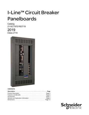
I-Line Circuit Breaker PanelboardsDimensionsDimensionsType HCJ—800 A Maximum Main Lugs32.008131.752.0026.3844516703/8 Dia.FlushLockSolid NeutralWhenRequired51HSurface Mounting HBAFlush Mounting H 2.00CCEnd ofMain LugsDE22.009.5Typical Box with InteriorTypical Box Side View559Typical 4-Piece Trimwith Optional Door241Typical EndwallFlush Mounting 34.25S/N870Surface Mounting 32.25A B CFront Center RearBusBusBus8195.005.00127Typical Mounting of BD, BG, BJ, BK, FA, FH,HD, HG, HJ, HL, HR, JD, JG, JJ, JL, JR, QB, QD, QG, QJCircuit BreakersINCHESDual Dimensions: MillimetersMainLugsAmpereRating400AfBfCf127Typical Wiring DiagramBranch connection phasing isdetermined by circuit breakerselection.Catalog NumberInteriorBox4-PieceTrimwithoutDoor ‡H4-Piece Trimwith Door ‡in.HCJ14484 bHC3248DB9 HC3248T( ) HC3248T( )D48.00HCJ14484CUHCJ23734HCJ32734 b HC3273DB9 HC3273T( ) HC3273T( )D a 73.00HCJ32734CUHCJ50914HC3291DB9 HC3291T( ) HC3291T( )D a 91.00Typical 4-Piece Trimwithout Optional 073418.40 467 12.80 325Continued on next page13 1998–2019 Schneider ElectricAll Rights Reserved07/2019
I-Line Circuit Breaker PanelboardsDimensionsMainLugsAmpereRatingCatalog NumberInteriorBox4-PieceTrimwithoutDoor ‡H4-Piece Trimwith Door ‡HCJ14486 bHC3248DB9 HC3248T( ) HC3248T( )DHCJ14486CUHCJ23736600HCJ32736 b HC3273DB9 HC3273T( ) HC3273T( )D aHCJ32736CUHCJ50916HC3291DB9 HC3291T( ) HC3291T( )D aHCJ14488HC3248DB9 HC3248T( ) HC3248T( )DHCJ23738HC3273DB9 HC3273T( ) HC3273T( )D a800HCJ32738HCJ50918HC3291DB9 HC3291T( ) HC3291T( )D a‡ Replace parentheses with “F” for flush or “S” for .50125766.00167628.9073418.4046712.80325a Two flush locks are supplied.b Add Cu to suffix for copper bus.1407/2019 1998–2019 Schneider ElectricAll Rights Reserved
I-Line Circuit Breaker PanelboardsDimensionsType HCJ—400 A Maximum Main Circuit Breaker32.008131.752.0026.3844516703/8 Dia.FlushLockSolid NeutralWhenRequiredService EntranceBarrier(Canada only)End ofMain CircuitBreaker Lugs51HSurface Mounting HBFlush Mounting H 2.00CACDE22.009.5Typical Box with InteriorTypical Box Side View559Typical 4-Piece Trimwith Optional Door241Typical EndwallFlush Mounting 34.25S/N870Surface Mounting 32.25A B CFront Center RearBusBusBus8195.005.00127Typical Mounting of BD, BG, BJ, BK, FA, FH,HD, HG, HJ, HL, HR, JD, JG, JJ, JL, JR, QB, QD, QG, QJKA, KH, QB, QD, QG, QJ, or QOCircuit BreakersDual Dimensions: fCf127Typical Wiring DiagramBranch connection phasing isdetermined by circuit breakerselection.Catalog NumberInteriorBox4-PieceTrimwithoutDoor ‡H4-Piece Trimwith Door ‡400HCJ14734MHC3273DB9 HCJ73T( ) HCJ73T( )D400HCJ23734MHC3273DB9 HCJ73T( ) HCJ73T( )D a400HCJ41914M bHC3291DB9 HCJ91T( ) HCJ91T( )D a400HCJ41914MCUHC3291DB9 HCJ91T( ) HCJ91T( )D‡ Replace parentheses with “F” for flush or “S” for surface.Typical 4-Piece Trimwithout Optional 43143143112.8012.8012.8012.80325325325325a Two flush locks are supplied.b Add Cu to suffix for copper bus.15 1998–2019 Schneider ElectricAll Rights Reserved07/2019
I-Line Circuit Breaker PanelboardsDimensionsType HCJ—800 A Maximum Main Circuit Breaker32.008131.752.0026.3844516703/8 Dia.BSolid NeutralWhenRequiredService EntranceBarrier(Canada only)End ofMain CircuitBreaker LugsSurface Mounting HFlushLockH51AFlush Mounting H 2.00CCDE22.009.50559Typical 4-Piece Trimwith Optional Door241Typical Box with InteriorTypical Box Side ViewTypical EndwallFlush Mounting 34.25S/N870Surface Mounting 32.25A B CFront Center RearBusBusBus8195.005.00127Typical Mounting of BD, BG, BJ, BK, FA, FH,HD, HG, HJ, HL, HR, , JD, JG, JJ, JL, JR, QB, QD, QG, QJCircuit BreakersDual Dimensions: fCf127Typical Wiring DiagramBranch connection phasing isdetermined by circuit breakerselection.Typical 4-Piece Trimwithout Optional DoorCatalog NumberInteriorBox4-PieceTrimwithoutDoor ‡H4-PieceTrim withDoor ‡ aHCJ18736MP HC3273DB9 HCM73T( ) HCM73T( )DHCJ36916MP HC3291DB9 HCM91T( ) HCM91T( )DHCJ18738MP HC3273DB9 HCM73T( ) HCM73T( )D800HC36918MP HC3291DB9 HCM91T( ) HCM91T( )D‡ Replace parentheses with “F” for flush or “S” for 6847447447447412.8012.8012.8012.80325325325325a Two flush locks are supplied.1607/2019 1998–2019 Schneider ElectricAll Rights Reserved
I-Line Circuit Breaker PanelboardsDimensionsType HCP—800 A Maximum Main kHBEnd ofMain Lugs51Surface Mounting HASolidNeutralWhenRequiredFlush Mounting H 2.00CCD10.3026230.009.50Typical Box with InteriorTypical Box Side View762Typical 4-Piece Trimwith Optional Door241Typical EndwallFlush Mounting 44.25S/N1124A B CFront Center RearBusBusBusSurface Mounting 42.2510738.00AfBfCf8.00203203Typical Mounting of BD, BG, BJ, BK, FA, FH,HD, HG, HJ, HL, JD, JG, JJ, JL, LA, LD, LG, LJ, LL, LR, MG, MJ,PG, PJ, PK, PL, QB, QD, QG, QJCircuit BreakersTypical Wiring DiagramBranch connection phasing isdetermined by circuit breakerselection.Typical 4-Piece Trimwithout Optional DoorINCHESDual Dimensions: MillimetersMainLugsAmpereRatingCatalog NumberInteriorBox4-Piece Trimwithout Door‡H4-PieceTrim withDoor ‡HCP14504HC4250DBHCW50T( )HCW50T( )DHCP23594HC4259DBHCW59T( )HCW59T( )D400HCP32684HC4268DBHCW68T( )HCW68T( )DHCP50864HC4286DBHCW86T( )HCW86T( )DHCP14506HC4250DBHCW50T( )HCW50T( )DHCP23596HC4259DBHCW59T( )HCW59T( )D600HCP32686HC4268DBHCW68T( )HCW68T( )DHCP50866HC4286DBHCW86T( )HCW86T( )DHCP14508HC4250DBHCW50T( )HCW50T( )DHCP23598HC4259DBHCW59T( )HCW59T( )D800HCP32688HC4268DBHCW68T( )HCW68T( )DHCP50868HC4286DBHCW86T( )HCW86T( )D‡ Replace parentheses with “F” for flush or “S” for 3244544544544544544544544541541541541517 1998–2019 Schneider ElectricAll Rights Reserved07/2019
I-Line Circuit Breaker PanelboardsDimensionsType HCP—1200 A Maximum Main Lugs42.0010672.002.1335.47515490127/64 Dia.VaultLockSurface Mounting HAHSolidNeutralWhenRequiredBEnd ofMain LugsFlush Mounting H 2.0051CCD10.3026230.009.50762Typical 4-Piece Trimwith Optional Door241Typical Box Side ViewTypical Box with InteriorTypical EndwallFlush Mounting 44.25S/N1124A B CFront Center RearBusBusBusSurface Mounting 42.25107310.35AfBfCf5.41263137Typical Mounting of BD, BG, BJ, BK, FA, FH,HD, HG, HJ, HL, JD, JG, JJ, JL, LA, LD, LG, LJ, LL, LR,MG, MJ, PG, PJ, PK, PL, QB, QD, QG, QJCircuit BreakersTypical Wiring DiagramBranch connection phasing isdetermined by circuit breakerselection.Typical 4-Piece Trimwithout Optional DoorDual Dimensions: INCHESMillimetersMainLugsAmpereRatingCatalog NumberInteriorBox4-Piece Trimwithout Door‡H4-PieceTrim withDoor ‡HCP145012N HC4250DBHCW50T( )HCW50T( )DHCP235912N HC4259DBHCW59T( )HCW59T( )D1200HCP326812N HC4268DBHCW68T( )HCW68T( )DHCP508612N HC4286DBHCW86T( )HCW86T( )D‡ Replace parentheses with “F” for flush or “S” for 54151807/2019 1998–2019 Schneider ElectricAll Rights Reserved
I-Line Circuit Breaker PanelboardsDimensionsType HCP—800 A Maximum Main Circuit Breaker42.0010672.002.1334.38515487327/64 Dia.HSolidNeutralWhenRequiredService EntranceBarrier(Canada only)End ofMain CircuitBreaker LugsB51Surface Mounting HAFlush Mounting H 2.00VaultLockCCD10.3026230.009.50Typical Box with InteriorTypical Box Side View762Typical 4-Piece Trimwith Optional Door241Typical EndwallFlush Mounting 44.25S/N1124A B CFront Center RearBusBusBusSurface Mounting 42.2510738.00AfBfCf8.30203211Typical Mounting of BD, BG, BJ, BK, FA, FH,HD, HG, HJ, HL, JD, JG, JJ, JL, LA, LD, LG, LJ, LL, LR,MG, MJ, PG, PJ, PK, PL, QB, QD, QG, QJCircuit BreakersTypical Wiring DiagramBranch connection phasing isdetermined by circuit breakerselection.INCHESDual Dimensions: MillimetersMainCircuitBreakerAmpereRatingTypical 4-Piece Trimwithout Optional DoorCatalog NumberInteriorBox4-Piece Trimwithout Door‡HCP18686M HC4268DBHCW68T( )HCP36866M HC4286DBHCW86T( )HCP18688M HC4268DBHCW68T( )800HCP36868M HC4286DBHCW86T( )‡Replace parentheses with “F” for flush or “S” for surface.600HABCD4-PieceTrim withDoor ‡in.mmin.mmin.mmin.mmin.mmHCW68T( )DHCW86T( )DHCW68T( )DHCW86T( .6818.6847447447447419 1998–2019 Schneider ElectricAll Rights Reserved07/2019
I-Line Circuit Breaker PanelboardsDimensionsType HCP-SU—800 A Maximum Main Circuit Breaker.422.00Service EntranceBarrier(Canada 86472102.0747Typical 2-Piece Trimwith Optional Door5326.16665Typical Box with InteriorTypical Box Side ViewS/NTypical Mounting of BD, BG, BJ, BK, FA, FH,HD, HG, HJ, HL, JD, JG, JJ, JL, LA, LD, LG, LJ, LL, LR,MG, MJ, PG, PJ, PK, PL, QB, QD, QG, QJA B CFront Center RearBusBusBusCircuit BreakersAfBfCfDual Dimensions: INCHESMillimetersBranch connection phasing isdetermined by circuit breaker selection.Typical 2-Piece Trimwithout Optional DoorMainCircuitBreakerAmpereRatingCatalog NumberInteriorBoxH2-Piece Trim without 2-Piece Trim withDoor ‡ aDoor ‡ a800HCP54868SUHC2686DBHC2686T( )‡ Replace parentheses with “F” for flush or “S” for surface.HC2686T( 6127.23692a Flush trims are 4-piece.2007/2019
With I-Limiter main circuit breaker, I-Line main circuit breaker panelboards are UL/CSA Listed for use on systems with up to a 200,000 maximum RMS symmetrical amperes available fault current (100 kA @ 600 VAC). I-Line Plug-on Unit with Surgelogic SPD SPD requires no wiring or conduit, saving labor time and materials.