Transcription
Spectra Catalog Cover:hires 2/22/13 8:39 AM Page 1GE Energy Spectra Series SwitchboardsInformation provided is subject to change without notice. Please verify all details with GE. All values are design ortypical values when measured under laboratory conditions, and GE makes no warranty or guarantee, express orimplied, that such performance will be obtained under end-use conditions.GE Energy41 Woodford Avenue, Plainville, CT 06062www.geindustrial.com 2013 General Electric Companyimagination at workimagination at workGET-8032C (02/13)
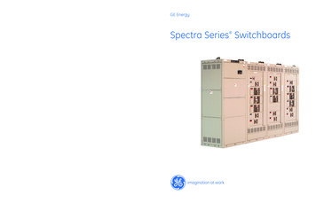
Spectra Series SwitchboardsContentsSection 1 - Introduction. . . . . . . . . . . . . . . . . . . . . . . . . . . . . . . . . . . . . . . . . . . . . . . . . . . . . . . . . . . . . . . . . . . 2Section 2 - Features and Characteristics. . . . . . . . . . . . . . . . . . . . . . . . . . . . . . . . . . . . . . . . . . . . . . . . . . 5Section 3 - Terminology . . . . . . . . . . . . . . . . . . . . . . . . . . . . . . . . . . . . . . . . . . . . . . . . . . . . . . . . . . . . . . . . . . 9Section 4 - Sizing and Dimension4.1 General . . . . . . . . . . . . . . . . . . . . . . . . . . . . . . . . . . . . . . . . . . . . . . . . . . . . . . . . . . . . . . . . . . . . . . . . . . 144.2 Typical Drawing . . . . . . . . . . . . . . . . . . . . . . . . . . . . . . . . . . . . . . . . . . . . . . . . . . . . . . . . . . . . . . . . . . 174.3 Class 1 Switchboard - Group Mounted . . . . . . . . . . . . . . . . . . . . . . . . . . . . . . . . . . . . . . . . . . . . . 184.4 Class 2 Individually Mounted Main Group Mounted Feeders/Class 5 Individually Mounted Switchboard . . . . . . . . . . . . . . . . . . . . . . . . . . . . . . . . . . . . . . . . . 224.5 Utility Metering Compartments. . . . . . . . . . . . . . . . . . . . . . . . . . . . . . . . . . . . . . . . . . . . . . . . . . . . 244.6 Outdoor Enclosures . . . . . . . . . . . . . . . . . . . . . . . . . . . . . . . . . . . . . . . . . . . . . . . . . . . . . . . . . . . . . . . 254.7 Instrument and Metering Arrangements . . . . . . . . . . . . . . . . . . . . . . . . . . . . . . . . . . . . . . . . . . . 254.8 Busway Entrance . . . . . . . . . . . . . . . . . . . . . . . . . . . . . . . . . . . . . . . . . . . . . . . . . . . . . . . . . . . . . . . . . 264.9 Low Voltage Transition Sections and Dual Voltage Switchboards . . . . . . . . . . . . . . . . . . . 264.10 Conduit Entrance Space . . . . . . . . . . . . . . . . . . . . . . . . . . . . . . . . . . . . . . . . . . . . . . . . . . . . . . . . . 274.11 Switchboard Weights . . . . . . . . . . . . . . . . . . . . . . . . . . . . . . . . . . . . . . . . . . . . . . . . . . . . . . . . . . . . 27Section 5 - Application Data5.1 Standards/Codes/Ratings/Conditions . . . . . . . . . . . . . . . . . . . . . . . . . . . . . . . . . . . . . . . . . . . . . . 325.2 Protective Device Ratings . . . . . . . . . . . . . . . . . . . . . . . . . . . . . . . . . . . . . . . . . . . . . . . . . . . . . . . . . 365.3 Power Break II Circuit Breaker . . . . . . . . . . . . . . . . . . . . . . . . . . . . . . . . . . . . . . . . . . . . . . . . . . . . 385.4 WavePro Low Voltage Power Circuit Breakers . . . . . . . . . . . . . . . . . . . . . . . . . . . . . . . . . . . . 405.5 High Pressure Contact Switches . . . . . . . . . . . . . . . . . . . . . . . . . . . . . . . . . . . . . . . . . . . . . . . . . . . 435.6 Molded Case Circuit Breakers . . . . . . . . . . . . . . . . . . . . . . . . . . . . . . . . . . . . . . . . . . . . . . . . . . . . . 445.7 Fusible Switches . . . . . . . . . . . . . . . . . . . . . . . . . . . . . . . . . . . . . . . . . . . . . . . . . . . . . . . . . . . . . . . . . . 505.8 Surge Protective Device . . . . . . . . . . . . . . . . . . . . . . . . . . . . . . . . . . . . . . . . . . . . . . . . . . . . . . . . . . . 515.9 Power Management Control System . . . . . . . . . . . . . . . . . . . . . . . . . . . . . . . . . . . . . . . . . . . . . . 525.10 Power Metering Products . . . . . . . . . . . . . . . . . . . . . . . . . . . . . . . . . . . . . . . . . . . . . . . . . . . . . . . . 525.11 Equipment Ground Fault Protection . . . . . . . . . . . . . . . . . . . . . . . . . . . . . . . . . . . . . . . . . . . . . . 545.12 Automatic Transfer Switches. . . . . . . . . . . . . . . . . . . . . . . . . . . . . . . . . . . . . . . . . . . . . . . . . . . . . 575.13 Wire/Lug/Cable . . . . . . . . . . . . . . . . . . . . . . . . . . . . . . . . . . . . . . . . . . . . . . . . . . . . . . . . . . . . . . . . . 63Section 6 - Additional GE Switchboard OfferingsClass 3 Switchboard. . . . . . . . . . . . . . . . . . . . . . . . . . . . . . . . . . . . . . . . . . . . . . . . . . . . . . . . . . . . . . . . . . 67Section 7 - CSI Specifications . . . . . . . . . . . . . . . . . . . . . . . . . . . . . . . . . . . . . . . . . . . . . . . . . . . . . . . . . . . . 71Reference Publications . . . . . . . . . . . . . . . . . . . . . . . . . . . . . . . . . . . . . . . . . . . . . . . . . . . . . . . . . . . . . . . . . . 80AppendixSeismic Compliance Certification . . . . . . . . . . . . . . . . . . . . . . . . . . . . . . . . . . . . . . . . . . . . . . . . . . . . . 81Trip Units by Main Breaker and Functions . . . . . . . . . . . . . . . . . . . . . . . . . . . . . . . . . . . . . . . . . . . . . 821
Spectra Series SwitchboardsSection 1 – IntroductionIntroductionSpectra Series SwitchboardsSeries SpectraSwitchboards offer a state-of the-artdesign that provides the high quality, safety andreliability long associated with GE group-mountedswitchboards. Spectra Series Switchboards are designedand manufactured to meet the stringent GE internalstandards along with NEMA, NEC, UL and cUL requirements. In addition, Spectra RMS and Record PlusCircuit Breakers meet all NEMA, NEC, IBC Seismic, ULand cUL requirements, plus those for JIS and IEC.Class 1 Group-Mounted Main and FeedersFront-Connected– 1200A Mains maximum– 1200A Feeders maximum– Rear alignment standard– Minimum depth 25"– Main lugs to 2000A– May be mounted against wall Main and Feeder Devices Group-Mounted– Molded case circuit breakers– Fusible switches type ADS (Spectra plug-in only)– Spectra RMS molded case circuit breakers– Spectra RMS molded case circuit breakers withmicroEntelliGuard trip units– Record Plus molded case circuit breakers– Current-limiting circuit breakers– Integral ground fault with Power , EntelliGuard TUand microEntelliGuard– Integral protective relay functions with EntelliGuard TUand microEntelliGuard– Integral network communications with EntelliGuard TUand microEntelliGuard– Ground fault alarm, neutral protection, ZSI andwaveform capture2
Spectra Series SwitchboardsSection 1 – IntroductionClass 2 Individually-Mounted Main, Group-MountedFeeders Front Accessible or Front/Rear– 5000A Mains maximum (WavePro )– 1200A group-mounted feeders maximum– Rear alignment standard or front and rear alignment– Utility CT Compartments– Main lugs to 6000A– Depths: Mains 25" - 60" Feeders 25” minimum– Plug-In or Bolt-On Construction for group-mountedfeeders Mains Individually-Mounted– Power Break II insulated case circuit breakers800-4000A with Power or EntelliGuard trip units– High pressure contact switches 800-4000A– Integral ground fault with Spectra Series, PowerBreak Series and WavePro– Integral protective relay functions withEntelliGuard TU– Integral POWER LEADER network communicationswith EntelliGuard TU– Bolted Pressure Switches 800 - 4000A– WavePro low voltage power circuit breakers3 Feeder Devices, Group-Mounted– Molded case circuit breakers– Fusible switches type ADS (Spectra plug-in only)– Spectra RMS molded case circuit breakers– Spectra RMS molded case circuit breakers withmicroEntelliGuard trip units– Record Plus molded case circuit breakers– Current-limiting circuit breakers– Integral ground fault with Power , EntelliGuard TUand microEntelliGuard– Integral protective relay functions with EntelliGuard TUand microEntelliGuard– Integral network communications with EntelliGuard TUand microEntelliGuard– Ground fault alarm, neutral protection, ZSI andwaveform capture
Spectra Series SwitchboardsSection 1 – IntroductionAV3 Access SwitchboardsSpectra Series SwitchboardsClass 3Class 5 Features and Options– Rear accessible– Front and rear alignment– Depths 50-60 inches– Molded case/insulated case/low voltage powercircuit breaker mains– Molded case and insulated case distribution sections– Copper bus– Feeder operating handles “thru the door” Main and Tie Devices - Individually Mounted– Spectra molded case breaker up to 1200A– PowerBreak II insulated case breaker up to 4000A– WavePro low voltage power circuit breaker up to5000A Feeder Devices, Individually Mounted– Spectra molded case circuit breaker - E (150A),F (250A), G (600A), K (1200A) frame breakers, 80 &100% rated– Current limiting breakers General Construction Features– Tin plated copper main bus - standard, silverplating optional– 2000A silver plated copper vertical (riser) bus –standard in MCCB sections– Shutters available on ICCB and LVPCB main and tiebreakers– 6000A main bus rating - maximum– Plug-in MCCB mounting with racking bolts - standard– Standard 30 cycle bus short circuit withstand ratingup to 85ka allows LVPCB main w/o instantaneous trips– 200ka bus bracing available with fused main device— Bare bus standard— Optional insulated horizontal main bus with phaseisolated vertical bus available in all sections— Bus sizing based on 1000A IN2 current density— 15/30/45 inch wide MCCB sections Individually-Mounted Mains and Feeders– 800A - 4000A— HPC Switch— PowerBreak II– 400A - 1200A— Spectra Breaker– 800A - 4000A Bolted Pressure Switch– WavePro Breaker (Mains & Tie Devices only)– 800A - 5000A WavePro BreakerNote: For applications requiring insulated/isolated bus,generator control and extensive relaying refer to AV-3or PowerBreak.4
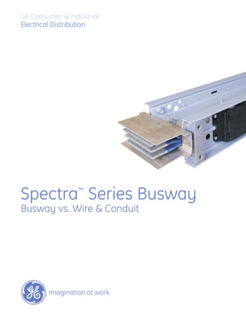
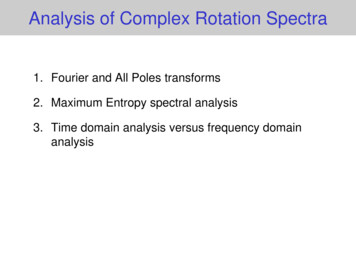
Spectra Series SwitchboardsSection 2 – Features and CharacteristicsFlexibility, Reliability, Simplicity & SafetyGE has designed a bus bar interior for use in SpectraSeries (group-mounted) Switchboards and SpectraSeries Power Panelboards.The distribution section interior is the basic buildingblock, designed for use with either fusible switches(plug-in only) or molded case circuit breakers, or both.The modularity of Spectra Plug-in is possible becausethe interior is designed to accept device modules withspring-reinforced jaws and pressure-locked connections. The jaws and connections are an integral part ofthe branch modules.Standard lifting plates, shown, are optional (NEMA 1 only).Spectra Series Plug-In circuit breaker modules accept standardoff-the-shelf GE breakers and are available for single- or doublebranch mounting (through 600A) without any modifications,assuring proper phase arrangement.Spectra Series Plug-In branch fusible modules can besingle- or double- (through 200A) mounted, two- or three-pole.5
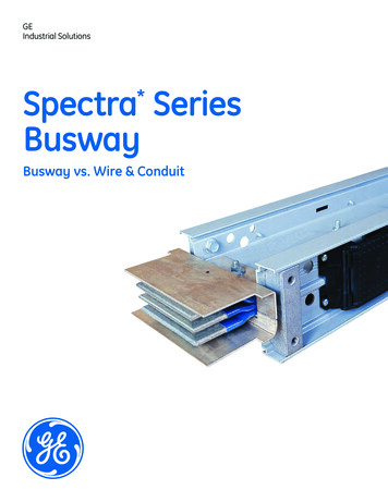
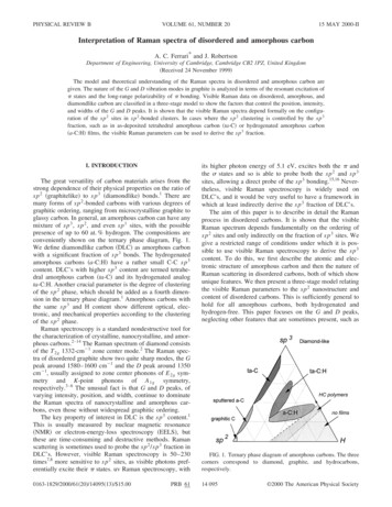
Spectra Series SwitchboardsSection 2 – Features and CharacteristicsSpectra Switchboard — Group-MountedInterior DesignThe vertical design of the bus maximizes convectiveheat transfer. The bus bar insulator system providesshort circuit bracing to 200 kA, 600-volt spacing (without having to add baffles) and eliminates the need forany additional insulation.Spectra Bolt-InVertical bus oriented edgewise for ease of boltedbreaker strap connections.Bolted connection betweenswitchboard vertical bus andbreaker primary connection.Spectra Plug-InMounting supportbrackets betweenbus support railsand mounting rails.Double-insulated system consisting of bussupport assemblies of molded, glass-filledpolyester insulation and insulating tubesover high-strength steel bolts spaced on 7"centers that prevent bus bars from distortingduring short-circuit conditions.Mounting rails (2)with means for positioning, engaging andgrounding pressurelocked connections.(plug-in only).Vertical bus is predrilled for locationof breakers in anystandard position.Anti-turn device utilized at the bolted connectionbetween the breaker strap and vertical bus.Isolated bussupport rails (2).Spectra Plug-In Switchboard ConstructionThe universal interior has made possible a family ofmodular components that provide the flexibility uniqueto the Spectra Series product line. By utilizing modularassembly and pressure-locked connections to theinterior, maintenance and tests are easier and faster.Standard bus is aluminum, heat ratedper UL. Optional ratings include 750A psior 600A psi aluminum and heat ratedper UL, 1000A psi or 800A psi copper. Allvertical bus bars are silver plated.Field changes are quick and easy.Interior cross-membersupports for mountingrails and bus supportrails.This innovative design approach also facilitates fieldreconfiguration. Branch fusible units can be removedand circuit breaker units substituted.Fusible switch and circuit breaker modules each consistof two assemblies: the protective device (fusible switchunit or molded case circuit breaker) and a connectingmechanism. The connecting mechanisms are the intermediate electrical/mechanical connections between theprotective device and the bus structure in the interior.The fusible connecting mechanism is in the samehousing as the fusible switch unit. The molded casecircuit breaker connecting mechanism is separate fromthe breakers and is designed to accept standard GEcircuit breakers.6
Spectra Series SwitchboardsSection 2 – Features and CharacteristicsThe electrical connection is made utilizing spring-reinforced jaws that engage the bus bars. This type ofproven design, long utilized in switchgear and busway,provides a reliable and superior electrical connection.Mechanical connection is made with a positive, selfaligning, spring-loaded locking device bolted to eachside of the mounting module. When the device moduleis inserted in the interior, this mechanism springs intoplace and positive engaging latches secure the moduleto the interior mounting rails.The fusible switch module has a self-aligni
Spectra Series Switchboards . proven design, long utilized in switchgear and busway, provides a reliable and superior electrical connection. Mechanical connection is made with a positive, self-aligning, spring-loaded locking device bolted to each side of the mounting module. When the device module is inserted in the interior, this mechanism springs into place and positive engaging latches .