Transcription
Linear MotorsInstallation & Operating Manual1/01MN1800
Table of ContentsSection 1General Information . . . . . . . . . . . . . . . . . . . . . . . . . . . . . . . . . . . . . . . . . . . . . . . . . . . . . . . . . . . . . . . . . . . . . . . . . . . . . . .1-1Overview . . . . . . . . . . . . . . . . . . . . . . . . . . . . . . . . . . . . . . . . . . . . . . . . . . . . . . . . . . . . . . . . . . . . . . . . . . . . . . . . . . . . .1-1Limited Warranty . . . . . . . . . . . . . . . . . . . . . . . . . . . . . . . . . . . . . . . . . . . . . . . . . . . . . . . . . . . . . . . . . . . . . . . . . . . . . . .1-1Safety Notice . . . . . . . . . . . . . . . . . . . . . . . . . . . . . . . . . . . . . . . . . . . . . . . . . . . . . . . . . . . . . . . . . . . . . . . . . . . . . . . . . .1-2Receiving . . . . . . . . . . . . . . . . . . . . . . . . . . . . . . . . . . . . . . . . . . . . . . . . . . . . . . . . . . . . . . . . . . . . . . . . . . . . . . . . . . . . .1-3Storage . . . . . . . . . . . . . . . . . . . . . . . . . . . . . . . . . . . . . . . . . . . . . . . . . . . . . . . . . . . . . . . . . . . . . . . . . . . . . . . . . . . . . . .1-3Unpacking . . . . . . . . . . . . . . . . . . . . . . . . . . . . . . . . . . . . . . . . . . . . . . . . . . . . . . . . . . . . . . . . . . . . . . . . . . . . . . . . . . . .1-3Handling . . . . . . . . . . . . . . . . . . . . . . . . . . . . . . . . . . . . . . . . . . . . . . . . . . . . . . . . . . . . . . . . . . . . . . . . . . . . . . . . . . . . . .1-3Section 2Installation & Operation . . . . . . . . . . . . . . . . . . . . . . . . . . . . . . . . . . . . . . . . . . . . . . . . . . . . . . . . . . . . . . . . . . . . . . . . . . .2-1Overview . . . . . . . . . . . . . . . . . . . . . . . . . . . . . . . . . . . . . . . . . . . . . . . . . . . . . . . . . . . . . . . . . . . . . . . . . . . . . . . . . . . . .2-1Location . . . . . . . . . . . . . . . . . . . . . . . . . . . . . . . . . . . . . . . . . . . . . . . . . . . . . . . . . . . . . . . . . . . . . . . . . . . . . . . . . . . . . .2-1Clean Room . . . . . . . . . . . . . . . . . . . . . . . . . . . . . . . . . . . . . . . . . . . . . . . . . . . . . . . . . . . . . . . . . . . . . . . . . . . . . . . . . . .2-1Mounting a Stage to the Machine Base and Payload To Stage . . . . . . . . . . . . . . . . . . . . . . . . . . . . . . . . . . . . . . .2-1LMAC Linear Induction Motor . . . . . . . . . . . . . . . . . . . . . . . . . . . . . . . . . . . . . . . . . . . . . . . . . . . . . . . . . . . . . . . . . . . .2-2LMBR Series Brush DC Linear Servo Motor . . . . . . . . . . . . . . . . . . . . . . . . . . . . . . . . . . . . . . . . . . . . . . . . . . . . . . .2-3LMBL Series . . . . . . . . . . . . . . . . . . . . . . . . . . . . . . . . . . . . . . . . . . . . . . . . . . . . . . . . . . . . . . . . . . . . . . . . . . . . . . . . . .2-4Brushless Linear Iron Core Servo Motor . . . . . . . . . . . . . . . . . . . . . . . . . . . . . . . . . . . . . . . . . . . . . . . . . . . . . .2-4Modular Magnet Track . . . . . . . . . . . . . . . . . . . . . . . . . . . . . . . . . . . . . . . . . . . . . . . . . . . . . . . . . . . . . . . . . . . . .2-6LMCF Series Brushless Linear Cog Free Servo Motor . . . . . . . . . . . . . . . . . . . . . . . . . . . . . . . . . . . . . . . . . . . . . .2-8LMNC Moving Coil Type . . . . . . . . . . . . . . . . . . . . . . . . . . . . . . . . . . . . . . . . . . . . . . . . . . . . . . . . . . . . . . . . . . . . . . . .2-9LMNM Moving Magnet Type . . . . . . . . . . . . . . . . . . . . . . . . . . . . . . . . . . . . . . . . . . . . . . . . . . . . . . . . . . . . . . . . . . . . .2-10LMPY Series Polynoid Linear Motor Holding Option . . . . . . . . . . . . . . . . . . . . . . . . . . . . . . . . . . . . . . . . . . . . . . . .2-11LMSS Series Linear Stepper . . . . . . . . . . . . . . . . . . . . . . . . . . . . . . . . . . . . . . . . . . . . . . . . . . . . . . . . . . . . . . . . . . . .2-13Roller Bearing Motor . . . . . . . . . . . . . . . . . . . . . . . . . . . . . . . . . . . . . . . . . . . . . . . . . . . . . . . . . . . . . . . . . . . . . . .2-13Air Bearing Motor . . . . . . . . . . . . . . . . . . . . . . . . . . . . . . . . . . . . . . . . . . . . . . . . . . . . . . . . . . . . . . . . . . . . . . . . . .2-14LMDS Series Dual Axis Linear Stepper Motor . . . . . . . . . . . . . . . . . . . . . . . . . . . . . . . . . . . . . . . . . . . . . . . . . . . . .2-15Positioning Stages . . . . . . . . . . . . . . . . . . . . . . . . . . . . . . . . . . . . . . . . . . . . . . . . . . . . . . . . . . . . . . . . . . . . . . . . . . . . .2-16Unpacking . . . . . . . . . . . . . . . . . . . . . . . . . . . . . . . . . . . . . . . . . . . . . . . . . . . . . . . . . . . . . . . . . . . . . . . . . . . . . . . .2-16Handling and General Guidelines . . . . . . . . . . . . . . . . . . . . . . . . . . . . . . . . . . . . . . . . . . . . . . . . . . . . . . . . . . . .2-16Stage Specifications Disclaimer . . . . . . . . . . . . . . . . . . . . . . . . . . . . . . . . . . . . . . . . . . . . . . . . . . . . . . . . . . . . .2-16LSE Series . . . . . . . . . . . . . . . . . . . . . . . . . . . . . . . . . . . . . . . . . . . . . . . . . . . . . . . . . . . . . . . . . . . . . . . . . . . . . . .2-17LSC Series . . . . . . . . . . . . . . . . . . . . . . . . . . . . . . . . . . . . . . . . . . . . . . . . . . . . . . . . . . . . . . . . . . . . . . . . . . . . . . .2-21LSS Series . . . . . . . . . . . . . . . . . . . . . . . . . . . . . . . . . . . . . . . . . . . . . . . . . . . . . . . . . . . . . . . . . . . . . . . . . . . . . . .2-24LSX Series . . . . . . . . . . . . . . . . . . . . . . . . . . . . . . . . . . . . . . . . . . . . . . . . . . . . . . . . . . . . . . . . . . . . . . . . . . . . . . .2-26Continued on next pageMN1800Table of Contents i
Bearing Maintenance . . . . . . . . . . . . . . . . . . . . . . . . . . . . . . . . . . . . . . . . . . . . . . . . . . . . . . . . . . . . . . . . . . . . . . . . . . .2-31Recirculating Bearing Rail And Block . . . . . . . . . . . . . . . . . . . . . . . . . . . . . . . . . . . . . . . . . . . . . . . . . . . . . . . . .2-31Cross Roller Type Bearing . . . . . . . . . . . . . . . . . . . . . . . . . . . . . . . . . . . . . . . . . . . . . . . . . . . . . . . . . . . . . . . . . .2-31Encoder Maintenance . . . . . . . . . . . . . . . . . . . . . . . . . . . . . . . . . . . . . . . . . . . . . . . . . . . . . . . . . . . . . . . . . . . . . . . . . .2-32RSF Series MSA6x Enclosed Type . . . . . . . . . . . . . . . . . . . . . . . . . . . . . . . . . . . . . . . . . . . . . . . . . . . . . . . . . .2-32RSF Series MS6x Open Type Glass Scale . . . . . . . . . . . . . . . . . . . . . . . . . . . . . . . . . . . . . . . . . . . . . . . . . . . .2-33Renishaw RGH22 series Open Type Metal Scale . . . . . . . . . . . . . . . . . . . . . . . . . . . . . . . . . . . . . . . . . . . . . .2-34ELGO Mix 4 series Magnetic Type . . . . . . . . . . . . . . . . . . . . . . . . . . . . . . . . . . . . . . . . . . . . . . . . . . . . . . . . . . .2-36ELGO Mix 5 series Magnetic Type . . . . . . . . . . . . . . . . . . . . . . . . . . . . . . . . . . . . . . . . . . . . . . . . . . . . . . . . . . .2-37Encoder Specifications . . . . . . . . . . . . . . . . . . . . . . . . . . . . . . . . . . . . . . . . . . . . . . . . . . . . . . . . . . . . . . . . . . . . . . . . .2-38Cables and Cable Chain Procedures . . . . . . . . . . . . . . . . . . . . . . . . . . . . . . . . . . . . . . . . . . . . . . . . . . . . . . . . . . . . .2-39Additional Cables . . . . . . . . . . . . . . . . . . . . . . . . . . . . . . . . . . . . . . . . . . . . . . . . . . . . . . . . . . . . . . . . . . . . . . . . . . . . . .2-40ii Table of ContentsMN1800
Section 1General InformationOverviewThis manual contains general procedures that apply to Baldor Linear Motor products. Be sure to readand understand the Safety Notice statements in this manual. For your protection, do not install, operateor attempt to perform maintenance procedures until you understand the Warning and Caution statements.A Warning statement indicates a condition that can cause harm to personnel. A Caution statementindicates a condition that can cause damage to equipment.Important:This instruction manual is not intended to include a comprehensive listing of all details for allprocedures required for installation, operation and maintenance. This manual describes generalguidelines that apply to most of the linear motor products shipped by Baldor. If you have aquestion about a procedure or are uncertain about any detail, Do Not Proceed. Please contactyour Baldor distributor for more information or clarification.Before you install, operate or perform maintenance, become familiar with the following: NEMA Publication MG-2, Safety Standard for Construction and guidefor Selection, Installation and Use of Electric Motors and Generators. The National Electrical Code Local codes and practicesLimited Warranty1. Baldor Electric motors are warranted for a period of one (1) year, from date of shipment from the factory or factorywarehouse against defects in material and workmanship. To allow for stocking and/or fabrication period and toprovide one year of actual service, the warranty period is extended for an additional period of six (6) months for atotal of eighteen (18) months from the original date of shipment from the factory or factory warehouse stock. In nocase will the warranty period be extended for a longer period. Baldor extends this limited warranty to each buyerof the electric motor for the purpose of resale and to the original purchaser for use.2. Baldor will, at its option repair or replace a motor which fails due to defects in material or workmanship during thewarranty period if:a. the purchaser presents the defective motor at or ships it prepaid to, the Baldor plant in Fort Smith, Arkansasor one of the Baldor Authorized Service Centers andb. the purchaser gives written notification concerning the motor and the claimed defect including the datepurchased, the task performed by the Baldor motor and the problem encountered.3. Baldor will not pay the cost of removal of any electric motor from any equipment, the cost of delivery to Fort Smith,Arkansas or a Baldor Authorized Service Center, or the cost of any incidental or consequential damages resultingfrom the claimed defects. (Some states do not allow the exclusion or limitation of incidental or consequentialdamages, so the above exclusion may not apply to you.) Any implied warranty given by laws shall be limited tothe duration of the warranty period hereunder. (Some states do not allow limitations on how long an impliedwarranty lasts, so the above limitation may not apply to you.)4. Baldor Authorized Service Centers, when convinced to their satisfaction that a Baldor motor developed defects inmaterial or workmanship within the warranty period, are authorized to proceed with the required repairs to fulfillBaldor’s warranty when the cost of such repairs to be paid by Baldor does not exceed Baldor’s warranty repairallowance. Baldor will not pay overtime premium repair charges without prior written authorization.5. The cost of warranty repairs made by centers other than Baldor Authorized Service Centers WILL NOT be paidunless first authorized in writing by Baldor.6. Claims by a purchaser that a motor is defective even when a failure results within one hour after being placed intoservice are not always justified. Therefore, Baldor Authorized Service Centers must determine from the conditionof the motor as delivered to the center whether or not the motor is defective. If in the opinion of a BaldorAuthorized Service Center, a motor did not fail as a result of defects in material or workmanship, the center is toproceed with repairs only if the purchaser agrees to pay for such repairs. If the decision is in dispute, thepurchaser should still pay for the repairs and submit the paid invoice and the Authorized Service Center’s signedservice report to Baldor for further consideration.7. This warranty gives you specific legal rights, and you may also have other rights which vary from state to state.MN1800General Information 1-1
Safety Notice:This equipment contains high voltage! Electrical shock can cause serious or fatal injury.Only qualified personnel should attempt installation, operation and maintenance ofelectrical equipment.Be sure that you are completely familiar with NEMA publication MG-2, safety standardsfor construction and guide for selection, installation and use of electric motors andgenerators, the National Electrical Code and local codes and practices. Unsafeinstallation or use can cause conditions that lead to serious or fatal injury. Only qualifiedpersonnel should attempt the installation, operation and maintenance of this equipment.WARNING:The magnetic attraction between the motor and the magnetassembly is extremely high. Keep fingers and other body partsaway from these objects to avoid injury by this magnetic attraction.WARNING:Use proper care and procedures that are safe during handling,lifting, installing, operating and maintaining operations.Improper methods may cause muscle strain or other harm.WARNING:Do not touch electrical connections before you first ensure thatpower has been disconnected. Electrical shock can cause seriousor fatal injury. Only qualified personnel should attempt theinstallation, operation and maintenance of this equipment.WARNING:Be sure the system is properly grounded before applying power.Do not apply AC power before you ensure that all groundinginstructions have been followed. Electrical shock can causeserious or fatal injury. National Electrical Code and Local codesmust be carefully followed.WARNING:This equipment may be connected to other machinery that hasmoving parts that are driven by this equipment. Improper use cancause serious or fatal injury. Only qualified personnel shouldattempt to install operate or maintain this equipment.WARNING:Do not by-pass or disable protective devices or safety guards.Safety features are designed to prevent injury to personnel ordamage to equipment. These devices can only provide protection ifthey remain operative.WARNING:Disconnect all electrical power from the motor windings andaccessory devices before disassembly of the motor. Electricalshock can cause serious or fatal injury.WARNING:Do not use these motors in the presence of flammable orcombustible vapors or dust. These motors are not designed foratmospheric conditions that require explosion proof operation.WARNING:Motors that are to be used in flammable and/or explosiveatmospheres must display the UL label on the nameplate.Specific service conditions for these motors are defined inNEC 70-599.Caution:1-2 General InformationBe careful when sliding the motor from its shipping container. Slidethe motor from the box onto a level, flat surface to prevent bending.Bending can damage the windings and commutators.MN1800
ReceivingEach Baldor motor is thoroughly tested at the factory and carefully packaged forshipment. When you receive your motor, there are several things you should doimmediately.1.Observe the condition of the shipping container and report any damageimmediately to the commercial carrier that delivered your motor.2.Verify that the part number of the motor you received is the same as the partnumber listed on your purchase order.StorageIf the parts are not put into service immediately, store them in a clean, dry and warmlocation. If the storage location is damp or humid, the exposed metal surface of themotors and windings must be protected from moisture. If the ambient temperaturedecreases suddenly, condensation may form. Protect all parts from moisture.UnpackingEach Baldor motor is packaged for ease of handling and to prevent entry ofcontaminants.HandlingRepairs1.To avoid condensation inside the motor, do not unpack until the motor hasreached room temperature. (Room temperature is the temperature of the roomin which it will be installed). The packing provides insulation from temperaturechanges during transportation.2.When the motor has reached room temperature, remove all protective wrappingmaterial from the motor.3.The magnet track sections may come packaged in one or more boxes. Do notflip any magnet track sections inside the box. Unpack the magnet tracksections one piece at a time. Place each section on a clean non–magneticsurface away from other magnet track sections and any other ferrous material.4.Always keep the magnet track sections at a safe distance from each other. Ifthe assemblies are to be left unattended for any period of time, precautionsshould be taken to prevent accidents due to the strength of the magnets (it isbest to leave them in their packing material to prevent injury due to magneticattraction). Persons who will come in contact with this assembly whilereceiving, transporting, storing, installing, disassembling or at any other time,must be made aware of this danger.Be extremely careful. Keep in mind:1.The magnetic attraction between the motor and the magnet assembly isextremely high. Keep fingers and other body parts away from these objects toavoid injury by this magnetic attraction.2.Use proper care and procedures that are safe during handling, lifting, installing,operating and maintaining operations.Improper methods may cause muscle strain or other harm.Baldor will not share any responsibility for damage caused by customer attempt to repairor modify a motor. Consult Baldor for any service.For further assistance please contact the factory:Baldor Linear Motion Products25026 Anza DriveSanta Clarita, CA 91355, USA(661) 257–0216 (phone)(661) 257–2037 (fax)MN1800General Information 1-3
1-4 General InformationMN1800
Section 2Installation & OperationOverviewInstallation should conform to the National Electrical Code as well as local codes andpractices. When other devices are coupled to the motor, be sure to install protectivedevices to prevent accidents. Machinery that is accessible to personnel should provideprotection in the form of guard rails, screening, warning signs etc.LocationThe motor should be installed in an area that is protected from direct sunlight, corrosives,harmful gases or liquids, dust, metallic particles, welding spatters and vibration.Exposure to these can reduce the operating life and degrade performance. Be sure toallow clearance for ventilation and access for cleaning, repair, service and inspections.Ventilation is extremely important. Be sure the area for ventilation is not obstructed.Obstructions limit the free passage of air. Motors get warm and the heat must bedissipated to prevent damage.These motors are not designed for atmospheric conditions that require explosion proofoperation. They must NOT be used in the presence of flammable or combustible vaporsor dust.Stages prepared for Class 10, 100 and 10,000 clean room requirements can be orderedas an option to our standard products. Materials must be suitable for the specifiedenvironment. The customer must perform the final cleaning due to contamination duringshipping and handling.The most common changes to the stages include the replacement of the bellows,installation of special greases, elimination of bearing shields and the removal of othernon–critical components that may contribute to particle generation.Clean RoomMounting a Stage to the Machine Base and Payload To StageSYour stage is provided with mounting holes to attach the stage to a machine base. Ifyour stage is supplied with bellows, you must remove the bellows to access themounting holes. The mounting holes are typically non–threaded, counter–boredholes that accommodate a variety of screw sizes. It is recommended that ahardened machine screw be used. Refer to the mechanical drawings provided withyour stage for mounting screw size and hole locations.SThe flatness of your mounting surface will greatly influence the flatness andstraightness specification of your stage. The stage structure will tend to mirror theflatness of the mounting surface. For the stage to maintain its specification, it mustbe mounted to a surface that is flat (maximum error of 0.0005 inches per foot). Amaximum of 0.010 inches per foot is the maximum mounting surface flatness errorallowable for operation of the stage. However, at 0.010 inches per foot mountingbase flatness, the stage flatness and straightness specification will be degraded.SThe mounting surface must be clean and free of particles that could affect flatness(particles that come between the stage and the mounting surface) . It is alsorecommended that the base of the stage be cleaned to remove contamination.Cleaning with alcohol or acetone is suggested, however avoid submersion orcontamination of the internal components.SWhen mounting the payload to the slide assembly, use the same precautionsmentioned for the stage. Refer to the stage outline drawing for hole locations andspecifications.SWhen pinning is required, Baldor recommends that the stage be machined andassembled at the factory.Note: It is strongly recommended that a thread locking compound be used whenmounting the stage to the base and when mounting the payload to the slideassembly.MN1800Installation & Operation 2-1
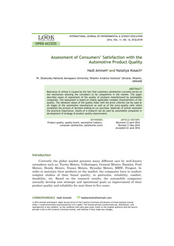
LMAC Linear Induction MotorGeneral Description:Single or three phase, linear AC induction motor primary.Construction:Epoxy encapsulated and steel laminated coil assembly (motor primary) Motor secondary(customer supplied) must conform to the following specifications: 1/8–inch aluminum orcopper plate backed by a 1/4 inch cold rolled steel plate. The width of the secondary mustbe at least the with of the motor coil assembly.Maintenance:Motor should be kept dry and relatively free of contamination. This motor is waterresistant, not water proof. Avoid submersion. Avoid contact with petroleum–basedsolvents. Alcohol or soapy water can be used to remove contaminants.Motor specifications:Refer to catalog or outline drawing supplied with motor for mechanical dimensions andelectrical specifications.Motor Mounting:Your motor may be supplied with either base or foot mounting, refer to catalog or outlinedrawing supplied with motor for mounting details and hole dimensions. It isrecommended that all available coil assembly mounting holes be utilized to properlysecure the coil assembly. If the coil is in motion, the motor wires must be strain relieved.We recommend that the motor secondary be secured with 1/4inch fasteners on the leftand right sides of the secondary, every four to six inches of its length. An air–gap of 1/8inch is recommended. Refer to linear induction motor duty cycle–force–current curves inthis booklet for information regarding the affects of air–cap size on motor performance.Electrical ConnectionsFor voltage and current specifications, refer to Catalog BR1800 or to documentationenclosed for custom motors. The 10 foot flying leads can be cut to remove excess lengthif required. Connectors are available; contact a Baldor representative for moreinformation.For single phase motors, refer to the table supplied with this booklet for capacitorselection.Motor WireFunctionPhase APhase BPhase CGroundThermal switchThermal warningGauge1010102020ColorRedBlue (substituted by black in older models)WhiteMotor housingOrange (two wires, interchangeable)Black (two wires, interchangeable)LMAC Connection Diagram2-2 Installation & OperationMN1800
LMBR Series Brush DC Linear Servo MotorMountingThe motor primary must be aligned (parallel) to the equipment guide ways within 0.005″(0.127mm) on each end. Use gauge blocks and shims as necessary. Precise parallelalignment of the motor to the equipment guideways is required. Align the stationary halfof the motor to the guideways. Then align the moving half with the stationary half.When securing the primary to the equipment base do not allow the screws to penetratethe motor more than .25″ deep (to prevent damage to the motor windings).To mount the motor secondary, slide the table over the secondary and align the mountingholes. The secondary is to be secured to the moving table with screws after the properamount of shims are added to maintain an air gap of .015″ min. to .020″ max. (unlessotherwise specified) between the secondary and the primary. This is achieved byensuring that the plastic shim provided does not bind anywhere over the length of theprimary when moving the table top with secondary back and forth by hand.The plastic shim between the primary and the secondary can now be removed. Be surethat the secondary is centered and runs parallel to the commutator to within .005″ at eachend.Electrical Check:With an ohmmeter across input terminals, verify that the resistance reading does not dropto zero when the secondary / commutator assembly is moved over the entire length of thestationary primary. If a zero reading is observed, inspect the connections between thecommutator brushes and the power input wires. In addition, inspect the connectionsbetween the motor windings and the commutator bar.Motor Removal:Insert the plastic shim between the primary and secondary to maintain the air gap. First,disconnect the power input wires. Next, remove the screws between the secondary andthe moving table as this allows the secondary to sit on the primary. Then remove themounting screws between the primary and the base. Finally, the complete motorassembly can be removed and placed on a level, flat surface.Secondary Removal:If just the secondary must be removed,slide the table with the secondary attached, to oneend of the primary. Insert a .015″ minimum plastic shim between the secondary and theprimary to maintain the air gap. Remove the screws between the secondary and thesliding table. Move the table out of the way and slide the secondary out using extremecaution so as to not damage the brushes. If brushes are worn out, contact NorthernMagnetics for replacement.Secondary Reinstallation: Place .015″ minimum plastic shim on primary face. Next place .015″ min fiberglass shimson the brush assembly and completely depress the brushes into their holders. With thebrushes toward the commutator bars, slide the secondary onto the primary face (with theshim in place). When the secondary is in place, gently remove the shim from betweenthe brushes and commutator bars.Note: Ensure that the shim between commutator and brushes has rounded endsand that they do not cut the leads to the commutator bars.Refer to “Mounting” instructions to reinstall.Brush Motor Connections: –MN1800Black / Red ( )White (–)Installation & Operation 2-3
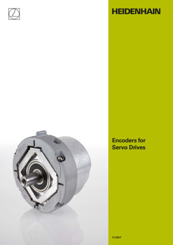
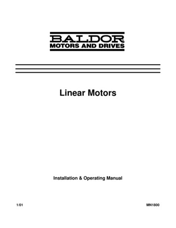
LMBL SeriesBrushless Linear Iron Core Servo MotorInstallationRefer to Figure 2-1.1. Install the magnet assembly onto the machine mounting base.2. With the slide assembly removed from the rails, install the coil assembly ontothe slide, tightening the mounting screws.3. Place a non–magnetic shim over the magnets, sized to cover all the magnets.(The shim thickness must be equivalent to the air gap specification. The normalair gap is 0.030″ 0.005″ unless otherwise specified).4. Install and push the slide along the rails, positioning the coil assembly directlyover the shim.(An alternate method is to install the slide on a set of rails that is identical to theone being used. Butt the temporary rails to the system rails and transfer theslide onto the system rails.)For either method, it is extremely important to uniformly tighten the mounting screws.Improper tightening will bend the primary or secondary and damage the motor.If there is not enough space to install the coil assembly as described, use this alternateprocedure.Alternate Installation Refer to Figure 2-1.1. Place the non–magnetic shim on the magnet track.2. With a firm grip on the coil assembly, place one end of it on the shim and slide itinto place, centered over the magnets. Be careful not to let the magnet and coil“Slam” together.3. Align the fastening screw holes on the slide with the holes on the coil assembly.4. Loosely install all the mounting screws.5. Insert enough shims between the slide and the coil assembly to fill the gap.6. Tighten all the mounting screws, alternating in a systematic manner whiletightening such that the coil assembly is drawn–up evenly leaving a uniform airgap between the coil assembly and the magnets. This air gap must bemaintained along the entire length of the magnet assembly i.e.; the coilassembly must never touch the magnets at any point when moving along thelength of the magnet assembly and the air gap specification must bemaintained at all times.7. Remove the shim that sets the air gap prior to operation.Figure 2-1 Air Gap AdjustmentSlideCoil AssemblyRailÉÉÉÉShim(if necessary)Air Gap (0.30 0.005)MagnetBase2-4 Installation & OperationMN1800
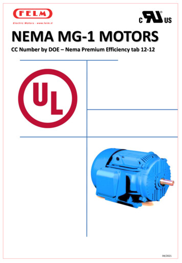
LMBL SeriesContinuedBrushless Linear Iron Core Servo MotorContinuedMultiple Coil Assembly OperationIn addition to maintaining an air gap, multiple coil assemblies must also maintain aspacing factor of 1.8″. In other words, the space between coil assemblies may vary,however, the distance from the front end of the first coil assembly to the front end of thenext must be a multiple of 1.8″. See Figure 2-2.Ensure that this spacing is established at the time of installation.Figure 2-2 Multiple Coil AssembliesRailCoil AssemblyCableMagnetAssemblyn (1.8″)Basen 1, 2, 3 , . . .Operation Considerations The motor must always be operated within the specified operating parameter limits.Exceeding those limits will permanently damage the motor Refer to the motorspecifications for operating parameter limits.The motor must never touch the magnets during operation. Refer to “Adjust Air Gap”.Remove the shim that sets the air gap between the motor and the magnets prior tooperation.Note: Be aware that the total bearing load includes the magnetic attractive force.The following steps must be completed to ensure safe and proper operation.1. Ve
The National Electrical Code Local codes and practices Limited Warranty 1. Baldor Electric motors are warranted for a period of one (1) year, from date of shipment from the factory or factory . WARNING: Be sure the system is properly grounded before applying power. . (661) 257- 0216 (phone) (661) 257- 2037 (fax) 1-4 General Information .