Transcription
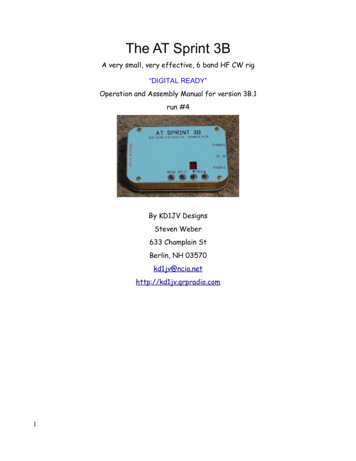
The AT Sprint 3BA very small, very effective, 6 band HF CW rig“DIGITAL READY”Operation and Assembly Manual for version 3B.1run #4By KD1JV DesignsSteven Weber633 Champlain StBerlin, NH 03570kd1jv@ncia.nethttp://kd1jv.qrpradio.com1
Table of ContentsBasic operation:.5Turning the rig on and off:.5Band selection and power up:.5Control switches:.5Frequency tuning: .6SPLIT MODES:.6Frequency annunciation while in Split modes:.6MENU:.6Quick selections: .6DFE Mode: .7Tune Mode: .7Battery Voltage:.7MENU switch only selected functions:.7Frequency readout: .7S: Selecting Keyer code speed; .8M: Keyer Memory entry: .8Sending messages: .9D: Digital modes: .9P: Program user preferences.9A: Alternative paddle .10Assembly:.13Reference pictures of the front and back sides of completed board:.15Overall placement diagrams. .16Parts check list: rough hole parts.23The SMT LED display should be soldered down first. .23Filter boards:.24Check out and Calibration:.25Reference Oscillator Frequency Calibration:.25Local Oscillator frequency trim:.26Band filter test and adjustment:.26Troubleshooting:.28Specific problems:.28IC Voltage tables: Receive mode.29Schematics.30Theory of Operation:.32Controller:.32DDS .32Receiver:.322
Transmitter:.33Digital mode operation:.34Entering ATS3-B into digital mode operation:.35Running Pocketdigi:.35Calibration:.353
Specifications:Frequency coverage: 80/40/30/20/17/15 meter bandsReceiver MDS, 0.2 uVSmall signal bandwidth 500 HzReceive current, no signal 35 ma.Transmit power output: 2.5 watts at 9V, 4.5 watts at 12 VTransmit current: 460 ma at 9 V, 610 ma at 12 VSupply voltage: 5.5 volts minimum, 12 volts maximum4
Operation:Basic operation:Turning the rig on and off:As there is no power switch, the rig is turned on and off by inserting or removing the power plug from the jack.Make sure the plug is firmly and fully inserted into the jack. Try not to put any sideways pressure on the plug, asthis may make the jack become intermittent.Band selection and power up:The desired band of operation is selected by inserting the appropriate band module into the SIP header socketon the main board and then powering up the rig. On power up, a voltage determined by a voltage divider is readso the processor knows which band module is in use. A one digit number relating to the band module installedwill be shown on the LED display and annunciated in Morse by the side tone. The standard QRP callingfrequency for that band (if any) will be loaded into the DDS as the initial operating frequency. You can then tunefrom there or use the Direct Frequency Entry function to move directly to another frequency.Hot swapping band modules:The firmware in the run #4 kits now allows for “hot swapping” of the band modules. This means you can changebands without removing and re-inserting the power plug. However, the processor will not know the band hasbeen changed until one of the switches is clicked. It doesn't matter which one, this is just needed to wake up theprocessor, which is normally asleep when it isn't doing anything else.Band Display/Morse Initial frequency80 M83.560 MHz40 M47.030 MHz30 M310.110 MHz20 M214.060 MHz17 M718.070 MHz15 M521.060 MHzControl switches:Four push button switches control theoperation of the ATS-3B. All switches havemultiple functions. The primary function ofeach switch is labeled in red in the switchfunction flow diagram shown to the right.Secondary functions are enabled by ashort click of either the MENU switch or theSPLIT switch, followed by clicking theswitch for the desired function. This allowsoften used secondary functions to bequickly accessed. Print out this page andcut out the diagram to paste in the lid ofyour tin as a reminder of switch functions.5
Frequency tuning:The operating frequency of the rig is controlled by the TUNE UP and TUNE DOWN buttons. These are labeledon the front panel with an up arrow and down arrow, respectively. “Clicking” the appropriate switch will incrementor decrement the current frequency by 50 Hz. Holding one of the tune switches closed for longer than one (1)second will start an auto-tune mode. The frequency will now change in 100 Hz steps at a rate of about 10 stepsa second as long as the switch is held closed. Tuning will revert back to normal one step, 50 Hz tuning when theswitch is released. The 100 Hz / 10 steps a second tuning rate is a compromise between being able to scan theband at a reasonable rate, while not being so fast its easy to miss weak signals.Tuning limits:The tuning range includes the entire band, though SSB reception is not possible since it will be received on thewrong sideband. A double beep will sound when the band edges are reached and tuning will stop there,preventing out of band transmission. A single beep will sound when you reach the edge of the USA CW bandsegment.SPLIT MODES:The ATS-3B has both RIT (Receive Incremental Tuning) and XIT (Transmit Incremental Tuning). Both modes areenabled by using the SPLIT switch and which mode is selected is determined by how long the switch is heldclosed. Once either RIT or XIT mode is enabled, the decimal point of the LED display will light to indicate splitmodes are active. There is no limit the the tuning range of RIT or XIT, other then the normal band limits.RIT is enabled by clicking and holding closed the SPLIT switch closed until the letter “R” is annunciated in Morseby the side tone. There is a slight delay after closing the switch and the sending of the “R”, as the split switch isalso used to activate the transmission of keyer messages.XIT is enabled by clicking and holding closed the SPLIT switch for one second after the “R” sounds and the letter“X” is annunciated. NOTE: If RIT is active, XIT can only be enabled by first exiting RIT mode.Split modes are exited by clicking and holding closed the SPLIT switch until a “dot” is sounded by the side tone.The decimal point on the LED display will go out and the original (Rx Tx) operating frequency which was in usewhen the split mode was activated will be restored.Frequency annunciation while in Split modes:Using the frequency annunciation while in split mode will indicate the delta (difference) between the receive andtransmit frequencies. For example, if you have tuned above the initial frequency by 1 kHz, the frequency willdisplay [01-0]. If you have tuned below the original frequency by 1 kHz, the frequency will display [99-0]. Inaddition, a “dot” (beep) will sound at each 1 kHz mark. If you tune back to the initial frequency, where receiveand transmit frequencies are equal, a [ 0 ] will flash on the display.MENU:The Menu switch is used to access, activate or escape from, the various functions and options available in therig. The Menu switch is sometimes used alone and sometimes in conjunction with the other switches to activatea function. In all cases, how long the menu switch is held closed will determine what function is to be activated.Quick selections:The DFE, Tune mode and battery voltage functions can be quickly accessed by using the Menu switch inconjunction with one of the three other switches. The MENU switch has to be clicked closed first, then one ofthe other three switches clicked within 1/2 second to activate the desired function.DFE (direct frequency entry) Menu, then SPLITTune Mode Menu, then Tune DownBattery Voltage Menu, then Tune Up6
DFE Mode:(“D” is annunciated when mode is activated)This mode allows you to enter a desired operating frequency using the paddle. This can be any frequency withinthe upper and lower band edges currently in use. Simply use the paddle to enter the frequency numbers inMorse, starting with the 100 kHz digit and ending with the 100 Hz digit (four numbers total). Zero's can be sentas a cut number “T” or full length. The LED display will flash the number which has been entered and the sidetone will sound a beep. If a number is miss sent, a “?” will be annunciated and that digit must be re-entered.When four digits have been entered, the rig will re-tune to that frequency. If the frequency entered is beyond thetuning limits, DFE mode will simply terminate and the frequency will remain where it was.NOTE: DFE mode is not available if the rig is in Straight key mode.DFE mode is not available when split operation is active.DFE mode can be escaped by clicking the Menu switch at anytime before 4 digits have been entered.Tune Mode:(“T” is annunciated when mode is activated, “t” shown on display)This mode allows you to toggle the transmitter on and off using the paddle. This makes it easier to adjust asmall antenna tuner if two hands are required to operate it (One to hold it in place and one to turn knobs). Thismode also allows you to make power output measurements, which require a steady carrier for a few seconds inorder to make an accurate reading.Toggle transmitter on: Tap the LEFT paddle.Toggle transmitter off: Tap RIGHT paddle.Exit Tune mode: Click Menu switch, “E” annunciated.NOTE: Tune mode is not available if the rig is in Straight key mode.Battery Voltage:This mode reads the input voltage to the board and then displays it on the LED display and annunciated inMorse. The letter “B” is sent before the digits during Morse annunciate. The voltage is measured after thereverse polarity protection diode and has a 5% accuracy.MENU switch only selected functions:Frequency, Keyer code speed (S), keyer memory entry (M), Digital modes (D), user settable options (P) andAlternative paddle (A) functions are selected using only the Menu switch. With the exception of Frequency, clickand hold closed the Menu switch until the letter on the 7 segment display appears and the Morse letteridentifying the desired function has been annunciated by the side tone, then release the switch. The switch mustbe released before the next letter in the menu sequence is annunciated to select the desired function.Frequency readout:A quick click and release of the MENU switch will activate the frequency readout. The default mode of readout isboth a numerical readout, sequenced one digit at a time on the LED display, and annunciated in Morse by theside tone. The 100 kHz, 10 kHz, 1 kHz and 100 Hz digits are indicated, in that order. MHz digits are implied bythe band in which the rig is currently operating on. A dash [ - ] on the display and an “R” in Morse indicates thedecimal point separating the 1 kHz digit from the 100 Hz digit. Zero's are sent as the cut number “T” in Morse.Therefore, a frequency such as 7.0400 will be sent as T4TRT in Morse and seen as 040-0 on the display. It ispossible to set the rig to indicate the frequency only with the LED display or send it only in Morse.7
S: Selecting Keyer code speed;(“S” on the display)Keyer speed has a range of about 10 to 35 wpm. Initial power on speed is set to 20 wpm.Click and hold closed the MENU switch until the letter “S” is annunciated and appears on the 7 segment display,then release the switch. This mode will automatically exit after 1 second if no action has taken place in that time.Code speed can be changed by using either the paddle or tune up and tune down switches. Code speeds areselected in approximatively 1 wpm increment using the paddle and 5 wpm increments by using the tune up andtune down switches . A beep will sound at each new code speed increment. The 5 wpm code speed incrementsprovided by the tune up and tune down switches gives a quick means of changing the code speed to more orless match another stations code speed during contests.Increase speed: Close RIGHT paddle or Tune Up switch.Decrease speed: Close the LEFT paddle or the Tune Down switch.NOTE: If the rig is in Straight key mode, the Tune up and Tune down switches are used to change code speed.While in Straight key mode, code speed increments in 1 wpm steps. This allows changing the code speed usedto send previously stored messages.Saving the selected code speed to memory:If you would like to save the current code speed to memory so that it will be loaded on power up as the defaultspeed, click the MENU button while the “S” is still shown on the display.M: Keyer Memory entry:(“n” on the display – the closest we can get to “m” with 7 segments)There are three keyer memories available, with a combined total of 124 character storage. Word spaces countas characters, as they take up one memory location. If more one than one message is desired, they must beentered in sequence, all in one session. Once a message is started to be entered, all previously storedmessages are deleted.Upon releasing the Menu switch after the letter “M” has been annunciated, the receiver will mute and entry of themessage via the paddle may begin. If keyer memory entry has been selected by mistake, clicking the Menuswitch will exit this mode without disturbing the contents of the memory, provided the paddle has not yet beenused.Timing for determining letter and word spaces is automatic and is based on “ideal” timing. Since many of ushave a hard time sending with ideal letter and word space timing, generally running letter groups and wordstogether, segments on the LED will flash to let you know when a letter time out or word space time out hasoccurred. The upper left LED segment (f) will flash at the letter space interval and the upper right segment (b)will flash at the word space time out. Paying attention to the flashing lights will allow you to enter a messagewithout timing mistakes.Entering more than one message.At the end of the first message, sending seven (7) (or more) dashes will signify the end of that message and thebeginning of the next. If a third message is desired, again send seven dashes at the end of the second message.If the available memory space for messages is exceeded before you can complete an entry, the memory entrymode will be terminated and the check message playback mode will start.8
Checking and storing the message:When you have finished keying in the messages, click the Menu switch. The message(s) will then play back soyou can check that they were entered correctly. If more than one message has been entered, you will hear theseven dashes indicating the break between them. If the playback is good and there are no mistakes, click theMenu button again to store the messages into Flash memory. If you need to redo the messages, click the Splitswitch and “EM” (Enter Message) will be sent by the side tone. Then re-enter in the messages.Sending messages:The SPLIT switch is clicked first, then within 1/2 second, click either the Tune Down, Tune Up or Menu switchto transmit the desired message. This new method eliminates the problem of accidentally sending message 1when using the split switch for it's primary function, turning on or off split modes.Message 1 is sent by clicking the Tune Down switch within 1/2 of a second after releasing the Split switch.Message 2 is sent by clicking the Tune Up switch within 1/2 of a second after releasing the Split switch.Message 3 is sent by clicking the MENU switch within 1/2 of a second after releasing the Split switch.Message Pause, Stop and Beacon mode:After a message has started being transmitted, it maybe paused or stopped using the paddle.Pause: Closing the RIGHT paddle or Tune Up switch will pause the message for as long as the paddle is heldclosed. Pause will start when a character being sent has finished sending.Stop: Closing the LEFT paddle or Tune down switch will terminate the transmission of the message when acharacter currently being sent has been completed.Beacon mode:Only message 1 can be used as a beacon. After message 1 has started transmitting, pause the message byclosing the RIGHT paddle (pause), then tap the LEFT paddle. Tune up and Tune down switches can also beused. The letter “B” will be annunciated and a lower case “b” will be displayed on the LED to remind you your inbeacon mode. There is a fixed length pause of a couple of seconds at the end of the message before it startssending again. The message maybe paused or stopped as described above. In addition, tapping either dot ordash paddle during the pause will terminate beacon mode.D: Digital modes:(“d” on the display)Thanks to the efforts of Vojteck Bubnic, OK1IAK, the ATS-3B can transmit a number of different types of digitalmodulation. However, since the rig was designed for CW use and hence uses a Class C PA and square wavedrive, some of the digital modes are more effective than others. Digital modes can only be used in conjunctionwith the Pocketdigi program. No other digital mode program will work, as they do not have the required specialcommunications protocols needed to tell the ATS3B what to do. Detailed operating instructions start on page 32of the manual. Pocketdigi version 1.0.11 is included on the CD. For the latest version of Pocketdigi, checkhttp://pocketdigi.sourceforge.netP: Program user preferences(“P” on the display)The following user preferences can be selected and stored in memory and are non-volatile. Only the functionsyou wish to change need to be selected.9
Iambic A or B mode, A mode initial defaultReverse Paddle dot and dash sense. Default is right, dot / left, dash. This applies only to the sending ofcode.frequency annunciation code speed, 20 wpm initial defaultfrequency readout -- Morse Display (default), Morse only or Display only.Iambic mode select: Click TUNE UP switch. Clicking the tune up switch will toggle between the A and B modes.The letter “A” or the letter “B” will be annunciated by side tone, indicating the selected mode.Reverse paddle sense: click the SPLIT switch. This will toggle between normal (Morse N) and reverse (MorseR) modesAnnunciation code speed: Click TUNE DOWN switch. This will set the code speed at which the nontransmitted Morse annunciated characters are sent at to the code speed the rig is currently set to. The letter “S”is annunciated to let you know something happened when you clicked the switch.Once the above selections have been made, click the MENU switch again to advance to the nextselections: (F will appear on the display)Frequency readout method: The method used for frequency readout maybe selected using these switches:SPLIT switch: Both Morse and display readout.Tune Up switch: Morse only readout. “MO” annunciated.Tune Down switch: LED Display only readout. “DO” annunciated.To store the preferences you have selected, click the MENU switch.A: Alternative paddle(“A” on display and side tone)This option allows using the Tune up and Tune down switches as a paddle. This option is a little clunky anddifficult to use, but it is useful if you want to save weight or have a problem develop with your external paddle inthe field. It will take some practice to get the hang of. The best method is to hold the tin with both hands andsend with your thumbs.When the alternative paddle mode is active, the keyer code speed is selected using the frequency tune up andtune down switches, as it would be in straight key mode. Code speed increments are at normal 1 wpm steps.DFE mode can be used as can entering in keyer memories. Reverse paddle option does not affect the dot anddash sense of these switches.Selecting alternative or normal paddle modes:Clicking the SPLIT switch toggles between these two modes. An “A” (alternative) or “N” (normal) is annunciatedindicating the mode selected. Escape and store by clicking MENU.Toggling between receive and transmit modes:There has to be a method of toggling the function of the tune up and down switches between normal frequencytuning and transmitting. This is done by a short click of the SPLIT switch. A 't” will appear on the display when theswitches are in transmit mode. There is a ½ second delay after clicking the split switch before the mode togglesbetween transmit or receive. This allows using the split switch to activate one of the keyer memories as wouldnormally be followed by a short click of the split switch.10
Straight key mode:Straight key mode is automatically detected and enabled when the rig is powered up when a monaural plug is inthe paddle jack. The sleeve of the mono plug grounds the dash input, which enables straight key mode. Straightkey mode also allows use of an external keyer if one so desires.Operating voltages:The ATS-3B has been optimized for operation at 9 volts, with a minimum operating voltage of 6 volts and amaximum of 12.0 volts. Since power output is dependent on supply voltage, power output will vary from a low ofabout 900 mw at 6 V and up to about 5 watts at 12 volts.NOTE: Since there is no fuse or current limiting in the rig, it is a good idea to use an in-line fuse in the powersupply cord. A 1 amp fuse for supplies of 9 volts or less and 2 amp fuse for supplies above 9 volts.HIGH SWR CAUTION: If operating the ATS-3B with supply voltages greater than 9 volts, please ensure there isa low SWR load connected to the rig. High SWR conditions (especially those which are reactive) when operatingabove 3 watts output may cause the PA stage to become unstable or cause the PA FETS to be damaged. Bevery careful when using a fully charged gell cell to power the rig!Spare DC power plug:Mouser part number 171-3218-EX 1.22Reprogramming the MPU.There is a row of pads above the MPU labeled “programmer”. These bring out the programming pins for theMPU, so that the firmware can be upgraded or changed. Several people have modified the firmware to provideadditional or different features to the rig. To reprogram the MPU, a simple level shifting interface must beconstructed to go between a PC with a parallel port and the programming pads on the main board. As shownbelow:In addition to the interface, you will need to install the MPS430 IAR development program to your PC. Thisprogram can be found in the MPS file folder with the name “FET R451.exe” Double clicking on this will start theinstallation program.The file folder labeled “MSP” on the CD should be copied to your hard drive, either in the C root directory or “MyDocuments” folder. Open the IAR program and select “open existing project” from the dialog box and direct it to11
look in the MPS folder. The project “ATS3B digi should show up and select that and click OK.The source code file will now be displayed and can now be worked on if so desired. To reprogram the MPU withthis file, connect the programming cable to the LPT1 parallel port of your PC, apply power to the ATS3B boardand then plug the header pins from the interface cable into the board. The ground pin end goes into the pad holeto the left of the MPU, as seen with the MPU below the programming port pins. A SIP socket is not needed forthe pins, the fit into the board is tight enough to the pins in the SIP plug to make reliable contact.Now click on the C-Sky icon in the tool bar (looks like a magnifying glass) and the programming should start.If you wish to program a different file into the MPU, add that file to the MPS folder and then add it to the list offiles. Click on that file name to make it active and proceed as above.Firmware revision number:The version of firmware can be found by holding down the MENU button as the rig is powered up. “Vx” will besent by the side tone, where x is the version number. For run 4 kits this number will be 4.12
Assembly: Your work area should be reasonably clean and uncluttered. Good lighting is a must. Empty the packets containing the parts into small paper bowls. This will ensure that they do not get lost. Somepeople like to do the assembly over a cookie sheet, as the lip around the edge helps to keep parts from going far.The metal sheet also provides some measure of static control, especially if you ground it. A white sheet under yourwork area could help in finding a part which might get away from you. A very thin (0.015”) solder is supplied for soldering the surface mounted parts. Very little solder is need for eachconnection. Ideally, you want a little convex fillet at the end of chip resistors and capacitors. Try not to end up will aball of solder at the end of the part. Do not use liquid solder flux. It simply makes a mess and is difficult to clean off the board and get out from underparts. If not completely removed from the board, it can cause problems. Before placing a part, lightly tin one pad for where it will go. You can speed assembly by tining one pad
The ATS-3B has both RIT (Receive Incremental Tuning) and XIT (Transmit Incremental Tuning). Both modes are enabled by using the SPLIT switch and which mode is selected is determined by how long the switch is held closed. Once either RIT or XIT mode is enabled, the decimal point of the LED display will light to indicate split modes are active.