Transcription
Installation,INSTALLATIONOperation,, OPERATION,andManualANDMaintenanceMAINTENANCE MANUAL
TABLE OF CONTENTSIntroduction 1.1Overview of the HX2 . 1-11.2Sales and Service Support . 1-21.3Key Features and Benefits of the HX2 . 1-21.4Materials of Construction . 1-21.5Flow, Pressure, and Temperature Ratings . 1-21.6Recommended Spare Parts . 1-31.7HX2 Rating Charts . 1-31.8HX2 Configuration and Ordering Code . 1-6Installation 2.1Shipment and Storage . 2-12.2General Installation Instructions and Guidelines . 2-12.3Major Components of the HX2 . 2-22.4Factory Pre-Sets . 2-32.5General Arrangement Dimensions and Weights – Vertical Units . 2-42.6General Arrangement Dimensions and Weights – Horizontal Units . 2-5Operation 3.1Operating Instructions and Guidelines– Start Up . 3-13.2Operating Instructions and Guidelines – Shut Down. 3-23.3System Wiring Diagram . 3-3Maintenance4.1HX2 Maintenance Schedule . 4-14.2Troubleshooting . 4-14.3HX2 Tube Bundle Maintenance . 4-54.4Flange Bolt Tightening Sequence and Torque Values . 4-74.5Circulator Pump Maintenance . 4-74.6Strainer Maintenance . 4-84.7Control Valve Maintenance . 4-9Appendix 1 – The Control Master Control PanelA.1General Operation . A-1A.2Start Up Procedures . A-2A.3Adjusting the Set Points . A-4A.4Adjusting the Alarm Settings . A-5A.5Alarm Menu . A-6A.6Fault Detection . A-7A.7Panel Box Layout and Component Listing . A-8A.8Panel Box Controller Connections . A-9A.9Control Panel Display Listings . A-10
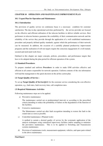
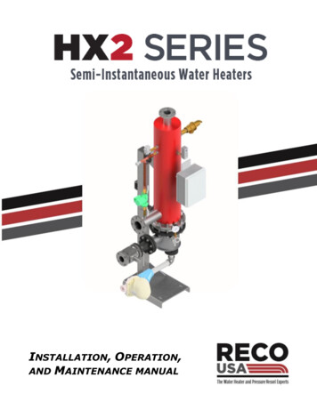
THE HX2 SERIESSEMI-INSTANTANEOUS WATER HEATERSINSTALLATION, OPERATION, AND MAINTENANCE MANUALINTRODUCTIONThis Installation, Operation, and Maintenance (IOM) manual is current as of the date issued,and RECO USA reserves the right to update, modify, amend, or change the informationcontained herein at any time without prior notice and without obligation to notify owners ofthis product of such changes.All installation, operation, and maintenance should only be attempted by authorized personneltrained to do so, and any personnel attempting these tasks should be completely familiar withthe contents of this IOM manual before attempting to do so.1.1 HX2 OverviewThe HX2 is RECO USA’s next generation of compact, semi-instantaneous water heatersusing available steam as the heating medium. Designed to the guidelines of TEMA,BOCA and IAPMO, these heaters can heat up to 150 GPM from 40 F to 140 F asstandard, with higher capacities possible.At the heart of the control system is theControl Master panel with a digital PACcontroller. The Control Master has an easyto-navigate LCD panel for local monitoringand set point adjustment. It accepts remoteset point changes and can re-transmit watertemperature via standard Modbus orBACnet communications protocols.An electrically operated, fast-acting V-ballcontrol valve is used to modulate the flow ofthe heating fluid.It has a 100:1rangeability which gives excellent control atall flow rates. Capacitors integrated into theactuator housing close the valve in theevent of loss of main power. Soft valveseats provide tight valve shut-off andprevent temperature rises at low load dueto valve seat leakage.1-1Fig. 1 – A horizontal HX2 unit (not all pipingshown or insulation jacket shown)
SECTION 1 - INTRODUCTIONHX2 SERIES1.2 Sales and Service SupportKey contacts at RECO USA for any quotation, sales, expediting, literature requests,shipping, or accounting issues can be reached at our main plant is located at 1839Dunbar Road, Cayce, SC 29033.Our main phone numbers are: Main office . (803) 794-3360 Main fax . (803) 791-3304To order replacement parts, contact RECO USA or your local authorized RECO USArepresentative.1.3Key Features and Benefits of the HX2 The HX2 safety system includes a pressure/temperature (P/T) relief valve, solenoidoperated, fail-open dump valve, and an automatic fail-closed steam inlet controlvalve. Lightweight, compact design fits through standard doorways and freight elevators. High accuracy temperature control of 4 F achieved. Continuous forced re-circulation eliminates temperature stratification and ensures auniform temperature distribution across all temperature sensors while also reducingscaling and sediment build-up on the tube bundles in the process. ASME constructed and stamped tank assures safe operation to 150 PSIG. All wetted parts on the heated side are lead-free and comply with NSF Standard 61and the requirements of the U.S. Safe Drinking Water Act. 1.4Support stand can comply with International Building Code (IBC) guidelines forseismic requirements.Materials of ConstructionThe standard HX2 tank and couplings are 316L stainless steel passivated to ASTM A380and A967. Piping is carbon steel, welded or threaded as appropriate. All units come witha flexible insulation jacket conforming to ASHRAE Std. 90.1, and the support stand andheating bundle head are powder coated for added durability.1.5Flow, Pressure, and Temperature Ratings Heated water recovery rate . 5 to 150 GPM Steam supply pressure . Up to 100 PSIG Cold water inlet pressure . Up to150 PSIG Heated water outlet temperature . Up to 210 F Design rating . ASME Boiler and Pressure VesselCode “U” stamped1-2
SECTION 1 - INTRODUCTION1.6HX2 SERIESRecommended Spare PartsThe table below shows the main spare parts available with the HX2, along with arecommendation for parts to be kept on hand to support the unit(s) in operation.CirculatorPump KitSteam Trap& Strainer KitTube Bundle 10 Yr. Operation Control PanelHigh LimitThermostat5 Yr. OperationInsulationJacketRTDAssembly Control ValveKitP/T ReliefValve SolenoidValvePressureGage KitAt Start UpOperation1.7RECOMMENDED SPARE PARTS PER UNITGasket KitTABLE 1-1 HX2 Rating ChartsTo select an HX2 the steam pressure (PSIG) available, amount of water (GPM) to beheated, and amount of heating ( F) to be done must be known. Heating is commonlyspecified in increments of 80 F (40 F to 120 F) or 100 F (40 F to 140 F).The first step is to locate the correct chart from the four that follow. Next locate theappropriate Steam Supply Pressure available (PSIG) along the X-axis, and the amount ofwater to be heated (GPM) along the Y-axis. Where the two intersect, find the ratingcurve corresponding to those conditions. If this intersection lies between two ratingcurves, choose the larger unit (higher curve).Notes:1. For copper-nickel tubes, de-rate the copper tube ratings shown by 20%.2. The ratings curves shown assume a tube bundle fouling factor of 0.00025 (hr. x ft 2x F / BTU).3. For applications with water as the heating source, contact RECO USA SalesDepartment.1-3
SECTION 1 - INTRODUCTION1.7aHX2 SERIESRating Charts for 40 F to 120 F Heating F Fto Heating120 F - –SingleWallCopper40 F to40120SingleWall,½” ODTubesCopper Tubes160120301501003014008030130Water to be Heated - 08090100Steam Supply Pressure -PSIG40 F FtoHeating120 F - –Double40 F to 120Double WallWall,Copper¾” OD TubesCopper Tubes1601501401203613012030120Water to be Heated - 030201000102030405060Steam Supply Pressure - PSIG1-4708090100
SECTION 1 - INTRODUCTION1.7HX2 SERIESRating Charts for 100 F HeatingtoHeating140 F -–Single40 F to 40140 F FSingleWallWall,Copper½” OD TubesCopper Tubes1401301203012011010030Warer to be Heaterd - 30405060708090100Steam Supply Pressure - PSIG40 F F Heatingto 140 F– -DoubleDoubleWall¾”CopperTubesTubes40 F to 140Wall,OD Copper14013012011012036Water to be Heated - 20060301000102030405060Steam Supply Pressure - PSIG1-5708090100
SECTION 1 - INTRODUCTION1.8HX2 SERIESHX2 Configuration and Ordering CodeThe following Configuration and Ordering Code defines the HX2 and can be found on theunit nameplate. When inquiring about a HX2 this code must be used. Doing so enablesus to handle requests quicker and assure the correct unit is being discussed.HX2 - H - 08036 - SS - CU - DW - MHeater SeriesHX2 Series Water HeaterBAS Interface M - ModbusA - BACnet IPB - BACnet MS/TPOrientationH - HorizontalV- VerticalHeater Tube Style DW - Double wall - ¾"SW - Single wall -½"Heater Size (Nominal)06030 - 6" D x 30" L06036 - 6" D x 36" LTube Material CU - CopperXX - Other08030 - 8" D x 30" L08036 - 8" D x 36" L10030 - 10" D x 30" L10036 - 10" D x 36" LTank/Shell Material SS - 316L stainless steelCN- Copper-NickelXX - Other12030 - 12" D x 30" L12036 - 12" D x 36" L Denotes standard configuration1.8a Sample Selection:The selected unit is a RECO USA HX2 series water heater model HX2-H-0836-SS-CUDW-M horizontal water heater with 8” diameter x 36” long heating element, 316Lstainless steel tank, ¾” copper double-wall tubes, and standard Modbus communicationinterface with the building automation system.1-6
THE HX2 SERIESSEMI-INSTANTANEOUS WATER HEATERSINSTALLATIONThe following guidelines must be followed when installing a HX2 series water heater.Failure to do so can result in faulty performance, field service / support charges, and/orvoiding of the warranty. Installation, operation, and/or maintenance should only beperformed by trained personnel knowledgeable in proper plumbing and electrical practices,and in particular should be thoroughly trained in working with high pressure steam systems.2.1 Shipment and StorageAll products are assumed to be installed and operated soon after receipt. RECO USAdoes not include any special preservation for long term storage, and assumes noresponsibility for storage deterioration after shipment unless explicitly agreed to inwriting beforehand. All units must only be lifted by the lifting lug(s) provided, asfailure to do so could result in damage to the unit.After the unit has been uncrated, it should be carefully examined for any damage thatmay have occurred in transit. If any damage is found and a shipping claim of damageis being made, immediately contact RECO USA or your local authorized sales, as wellas the common carrier who delivered the unit(s).2.2 General Installation Instructions and Guidelines2.2.1The HX2 is designed for indoor use only, unless specified otherwise. Install theunit so there is adequate room around the unit for servicing. Provide clear access(see Figures 1.7 and 1.8) to permit tube bundle removal.2.2.2The unit should be level to permit proper drainage and must be anchored securelyto the floor. It should be on a level surface with no more than 0.5 slope andcapable of supporting the total weight of the unit when filled to capacity.2.3.3All steam, water, and condensate lines should be installed in accordancewith good engineering practices. Note that the ASME code requires that noreduction in pipe size, and no valves or other restrictions may be introducedin the piping from the relief valve.2.2.4After mounting the unit in place, connect the cold-water source to the unit’s coldwater inlet, and then the hot water discharge from the unit to the building hotwater feed line. The locations of these are indicated on the General Arrangementdrawings in Figures 1.7 and 1.8.2.2.5Next connect the steam outlet trap and strainer (supplied loose) to the unit, andconnect this line to the steam condensate return line.2-1
SECTION 2 - INSTALLATIONHX2 SERIES2.2.6Pipe the relief valve, tank drain, and solenoid dump valve separately to a suitable floordrain. Do not install a valve in relief valve or solenoid valve line, as that would defeatthe purpose of these drain lines.2.2.7Complete the installation by making the appropriate electrical connections to the maincontrol panel.2.2.8A manual shut off valve of the same size as the inlet water line should be installedupstream of the cold-water supply to the unit, and kept in the closed position until theinstallation is complete. A shut off valve of the same size as the hot water discharge lineshould also be installed at the unit’s hot water discharge. Together, these two valves willisolate the heated water side of the unit.2.2.9A manual shut off valve of the same size as the steam inlet line should be installedupstream of the steam supply to the unit.2.2.10 The condensate return line should have a shut off valve of the same size as the lineinstalled downstream of the unit to isolate it from the system. This valve will also preventbackflow of steam if the line is disconnected at the unit’s hot water discharge.2.2.11 All piping is pressure tested at the factory for leaks prior to shipment. However, pipingconnections can loosen during transit, and installation, resulting in leaking connections,damaged threads, etc. Once installed and started, all piping should be inspected again,and any leaks or damage corrected at the time of installation.2.2.12 An inlet steam strainer and steam trap immediately upstream of the inlet control valve(not provided by RECO USA) is necessary for optimal system performance. A condensatestrainer and steam trap are provided loose as standard, with mounting and connectionto be done in the field by others.2.2.13 A suitable means, such as a gravity drain or condensate pump system, must be providedto remove condensate from the unit and otherwise prevent condensate from collectingand blocking its ability to freely flow away from the unit.2.3 Major Components of the HX2A general listing of the major, external components of an HX2, and their function, are asfollows:2.3.1The solenoid valve is an electrically actuated, normally closed valve that opens torelieve tank pressure once a pre-set high temperature limit is exceeded. It should beindependently piped to a suitable gravity drain using a line size of the same size asthe solenoid valve discharge.2.3.2The resistance temperature detector (RTD) is a temperature probe immersed in thetank flow stream near the discharge nozzle. Under normal operation it is a selfcontained device not requiring routine maintenance.2.3.3The high-limit thermostat is a primary safety feature that upon reaching a pre-sethigh temperature limit, interrupts power to the control valve, causing it to close, andenergizes the solenoid valve to open.2.3.4The pressure/temperature (P/T) relief valve is a secondary mechanical safety deviceused to protect against over-pressure or over-temperature conditions within the unittank. It should be independently piped to a suitable gravity drain using a line size ofthe same size as the relief valve discharge.2.3.5The circulator pump consists of a pump/motor assembly with companion flanges. Itprovides continuous circulation throughout the tank, which ensures a uniformtemperature distribution across all temperature sensors.2-2
SECTION 2 - INSTALLATIONHX2 SERIES2.3.6An electrically operated, fast-acting V-ball control valve is used to modulate flow ofheating medium to the unit. It has a 100:1 rangeability which gives excellent controlat all flow rates. Capacitors integrated into the actuator housing close the valve inthe event of loss of power.2.3.7The steam trap and strainer are a float and thermostatic (f & t) type steam trap and“Y” type strainer. These components are supplied loose for connection at the steam(condensate) outlet of the heating tube bundle.2.3.8The insulation jacket is a flexible, Velcro-attached design specific to the unit itinsulates. All cut outs and openings for piping and instrumentation are provided foreasy installation without the need for field modification.2.3.9The tube bundle is provided pre-assembled into the heating tank, with all piping andcontrols installed and tested, ready for start-up and operation.2.3.10 The Control Master control panel is a complete, pre-assembled and pre-wired unitwith a programmable automation controller (PAC) and easy to navigate LCD panel forlocal monitoring and set point adjustment.2.4 Factory Pre-SetsAll temperature settings for the unit are factory set for the specified outlet temperaturerequirements. This is typically 120 F or 140 F.2.4.1 The temperature pre-sets start with the RTD sensor and PID control loop tied to thecontrol panel PAC. It is set to the specified outlet water temperature, and modulatesthe control valve position to maintain the inflow of steam corresponding to the demandfor hot water. Upon reaching the desired water outlet temperature, the control valvewill back off to the point it may fully close. Outlet water temperature is controlled to /- 4 F.2.4.2 The high temperature alarm is set to 10 F above the outlet temperature setting. Uponreaching this setting the control panel LCD display will blink and send an alarm signalto the BAS (if so wired). Upon returning below this high temperature setting, thesystem will automatically come out of alarm mode and reset itself without the need fora manual reset.2.4.3 In addition to the RTD sensor and PID control loop, a separate high temperature limitswitch is provided. This is pre-set to 10 F above the high temperature alarm setting(which is 20 F above the outlet water temperature setting). In the event the hightemperature limit switch is tripped, it will cut power to the control panel. This will deenergize the steam inlet control valve, causing it to fail closed and cut off any furthersupply of steam to the unit, and energize the tank-mounted solenoid valve, causing itto open and relive any pressure in the tank.2.4.4 As a third safety feature, a factory pre-set pressure / temperature relief valve mountednear the tank outlet will open upon reaching its high pressure or temperature setting,relieving the contents of the tank until the internal pressure in the tank falls below thevalve settings. These settings are typically 150 PSIG and 210 F, respectively.2-3
SECTION 2 - INSTALLATIONHX2 SERIES2.5 General Arrangement Dimensions and Weights – Vertical UnitsTABLE 2-1Basic SizeVERTICAL UNIT DIMENSIONSABEHIL06030 / 060362”1 ½"46.7595.034.253208030 / 080363”2 ½"46.7597.034.2510030 / 100364”3"46.7599.012030 / 120364”3"46.75100.0RSTVWFNPT24.017.751” FNPT / 1.25” FNPT33.0930 / 950381.5 FNPT24.017.751.5” FNPT / 2” FNPT35.01,125 / 1,15533.75491.5 FNPT24.017.752.5” 150 Lb. RFSO37.01,380 / 1,42033.75511.5 FNPT24.017.753” 150 Lb. RFSO39.01,655 / 1,705¾Wt. (lbs.)Notes:1. Dimensions “A” and “B” are nominal sizes for ANSI 150 lb. raised face, slip on (RFSO) flange.2. All dimensions in inches, unless noted otherwise.3. Weights shown are net empty weight for a standard HX2 unit. Crating or shipping materials not included.2-4
SECTION 2 - INSTALLATIONHX2 SERIES2.6 General Arrangement Dimensions and Weights – Horizontal UnitsTABLE 2-1Basic SizeABEHIHORIZONTAL UNIT DIMENSIONSKRSTUVWFNPT2439411” / 1.25” FNPT33985 / 1,0051.5 FNPT2439411.5” / 2” FNPT351,180 / 1,210741.5 FNPT2439412.5” 150 Lb. RFSO371,435 / 1,475771.5 FNPT2439413” 150 Lb. RFSO391,710 / 1,765L06030 / 060362”1 ½" 23.7595.034.25 37.75 71.7508030 / 080363”2 ½" 23.7597.034.25 38.7573.510030 / 100364”3"23.7599.033.75 39.7512030 / 120364”3"23.75 100.0 33.75 40.75¾Wt. (lbs.)Notes:1.2.3.4.Dimensions “A” and “B” are nominal sizes for ANSI 150 lb. raised face, slip on (RFSO) flanges.All dimensions in inches, unless noted otherwise.Weights shown are net weight for a standard HX2 unit. Crating or shipping materials not included.Allow “L” dimension plus 6 inches for tube bundle removal clearance.2-5
SECTION 2 - INSTALLATIONHX2 SERIESTHIS PAGE LEFT INTENTIONALLY BLANK2-6
THE HX2 SERIESSEMI-INSTANTANEOUS WATER HEATERSOPERATION3.1 Operating Instructions and Guidelines – Start UpBefore starting, read this HX2 Installation, Operation, and Maintenance Manual (IOM) in itsentirety prior to proceeding. The separate section on the Control Master operation(Appendix A) contains important information on pump on/off, and control valve open/closeinstructions that should be understood before starting the unit up.3.1.2Begin with all assuring all steam, condensate, and water valves closed.3.1.3Slowly open the inlet and outlet isolation valves at the pump on the circulator line.3.1.4Open the cold-water inlet valve and fill unit with cold water. The tank can be ventedby lifting the bypass lever on relief valve to allow trapped air to escape. Allow therelief valve lever to return to its original closed position once all traces of air havebeen vented from the unit. Leave the cold-water valve open.3.1.5Activate (Enable) the circulator pump at the control panel LCD display. Never operatethe pump without the unit being filled with water and all isolation valves open, or damageto the pump will result from dry running.3.1.6Gradually open the control valve to allow steam to enter the tube bundle. Monitor thetank temperature until the desired temperature is reached. If the temperature regulatorshuts off before the desired temperature is reached, or if significant over-shoot occurs,adjustment of the temperature settings may be required.3.1.7After any control valve adjustments have been made, and the desired watertemperature has been reached, open the valves on the hot water discharge andbuilding recirculation line.3.1.8Check for any leaks, as tightening of gasketed joints may be required after unit hasbeen heated.3.1.9Never allow the unit to operate beyond its design conditions (see Section 1.5).3.1.10 Never break any joint, gasketed surfaces, or threaded connections while the unit isin operation. Instead, the unit must be isolated and de-energized, with adequatetime given for it to cool (see Shut Down instructions, Section 3.2).3-1
IOM SECTION 3- OPERATIONHX2 SERIES3.2 Operating Instructions and Guidelines – Shut DownBefore shutting the unit down, assure that hot water demand for the unit is not needed.The operator should also re-read this HX2 Installation, Operation, and Maintenance Manual(IOM) in its entirety prior to proceeding.To shut the unit down, follow the sequence as listed:3.2.1 Close the inlet control valve to cut off incoming live steam to the unit.3.2.2 Close the hot water discharge valve at the tank outlet.3.2.3 Close the building recirculation valve, isolating the unit from the building steamline.3.2.4 Close the water inlet valve to cut off incoming cold water to the unit.3.2.5 Turn off all electrical power to the unit control panel.3.2.7 With the unit now isolated by the valving, and de-energized electrically, lift therelease lever on the tank relief valve to evacuate hot water in the tank until thetank interior is brought to atmospheric pressure.3.2.8 Open the tank drain valve to drain the remaining water from the tank.3-2
IOM SECTION 3- OPERATIONHX2 SERIES3.3 System Wiring Diagram - Sizes 0630 and 06363-3
IOM SECTION 3- OPERATIONHX2 SERIES3.4 System Wiring Diagram - Sizes 0830 Through 12363-4
THE HX2 SERIESSEMI-INSTANTANEOUS WATER HEATERSMAINTENANCE4.1 HX2 Series Maintenance ScheduleEven under the best of conditions, some regular maintenance on the HX2 is needed. Thetable below is a general guide as to how often this should be done.TABLE 4-1ItemRECOMMENDED INSPECTION INTERVALSAt StartUpWeeklyMonthlyQuarterlyAnnuallyCirculator Pump Control Panel Control Valve Drain Valve Pressure Gauge Heat Exchanger Gaskets Heat Exchanger Tube Bundle Manual Shut Off Valves Piping Connections Pressure / Temperature Relief Valve Solenoid Valve Steam Trap Support Stand Strainer Vacuum Breaker Biannually 4.2 TroubleshootingThe table below is a quick summary of common problems encountered, and their mostlikely causes, along with a recommendation for how to correct them. These are by notintended to be an all-inclusive, definitive answer to every field issue that can occur, butrather a reasonable approach to common problems considering the highest likelihood ofroot cause, and how we would suggest addressing those problems based on our ownexperience.4-1
IOM SECTION 4- MAINTENANCEHX2 SERIESTABLE 4-2TROUBLESHOOTING FIELD GUIDELikely Cause and Suggested RemedyProblem123Unit fails to reach required outlet water temperature Outlet water temperature too high Outlet water temperature unsteady 456 78910 Tube bundle leakingOutlet water temperature decreasing over time Relief valve poppingControl valve cycling, non-steady operation Steam discharging into condensate line4.2a Troubleshooting Issues and Remedies1 – The RTD sensor is not reading the temperature correctly.Remedy - Check the water temperature with a temperature gauge known to beaccurate. Replace the RTD if it is found to be faulty.2 – The inlet steam is not at the specified temperature, pressure, or flow rate.Remedy - Check the inlet steam pressure with a suitable pressure gauge with thecontrol valve fully open. If the reading is low, adjust the inlet pressure to therequired inlet pressure. If this initial reading is correct, the pressure gauge readingshould reach the design pressure for the steam in the heating coil as the watertemperature in the tank approaches shut off.3 – The Condensate return piping has not been installed properly, and the condensateis not able to freely drain.Remedy - Re-route the condensate return line and assure there are no restrictionsin that line and that the condensate is either being pumped away or free to gravitydrain.4 – The outlet steam trap or strainer basket are clogged.Remedy - Check both for fouling and clean as necessary. Follow the proceduresgiven in Section 4.6 for further details on how to do this.5 – The steam control valve or not opening or closing properly.Remedy - Follow the procedures given in Section 4.7 for further details on how todo this.6 – The high temperature sensor is not set correctly or is not functioning properly.Remedy - Check the setting on the unit and re-set as necessary. If this does notwork the sensor will need to be replaced.7 – There is a leak with one or more tubes in the tube bundle, either directly in a tubeor at the tube-to-tubesheet interface, causing tank water or steam condensate toleak out the tube bundle weep hole area.Remedy – A tube has worn through, either through erosive or corrosive wear, or4-4
IOM SECTION 4- MAINTENANCEHX2 SERIESits connection at the tube sheet has been compromised. The heating tube bundlewill have to be removed, and cleaned or replaced. Follow the procedures given inSection 4.3 for this.8 – The heating tube bundle is heavily scaled or otherwise damaged.Remedy – The heating tube bundle will have to be removed, and cleaned orreplaced. Follow the procedur
The HX2 is RECO USA's next generation of compact, semi-instantaneous water heaters using available steam as the heating medium. Designed to the guidelines of TEMA, BOCA and IAPMO, these heaters can heat up to 150 GPM from 40 F to 140 F as standard, with higher capacities possible. At the heart of the control system is the