Transcription
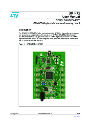
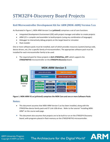
STM32F4-Discovery Board ProjectsKeil Microcontroller Development Kit for ARM (MDK-ARM) Version 5.xxAs illustrated in Figure 1, MDK-ARM Version 5.xx (µVision5) comprises a set of core functions: Integrated Development Environment (IDE) with project manager and editor to create projectsARM C/C compiler and assembler to build projects (using any combination of languages)Debugger to interactively debug projects on the target board or simulatorPack installerOne or more software packs must be installed, each of which provides resources (system/startup code,device drivers, etc.) for a specific family of microcontrollers. The appropriate software pack must beinstalled for each microcontroller family to be used. The required pack for these projects is Keil::STM32F4xx DFP, which supports theSTM32F407VG microcontroller on the STM32F4-Discovery board.DesktopIconFigure 1. MDK-ARM V5.xx (µVision5) comprises the MDK Core and one or more Software PacksNotes: This document assumes that MDK-ARM Version 5.xx has been installed, along with theSTM32F4xx device family pack and ST-Link USB driver. Refer to the tutorial “Installing MDKARM” on the course web page. This document also assumes that projects are to be built to run on the STM32F4-Discoveryboard, with programs placed in flash memory on the STM32F407VG microcontroller.
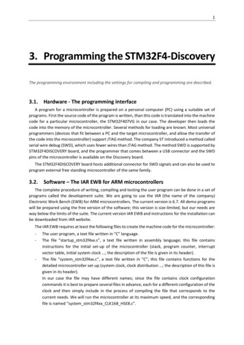
Creating a New Project for the STM32F4-Discovery Board1. Open µVision5 and from the menu bar select: Project New µVision Project. In the Create NewProject Window (Figure 1), navigate to the folder in which you want to create the project (create thefolder if necessary), enter a project name (ex. Project1), and click Save.It is recommended that a separate folder be created for each project.Project FolderProject FileFigure 1. Creating a new µVision project “Lab1”2. In the Select Device for Target window (Figure 2), select microcontroller STM32F407VG.Figure 2. Select the STM32F407VG microcontroller.
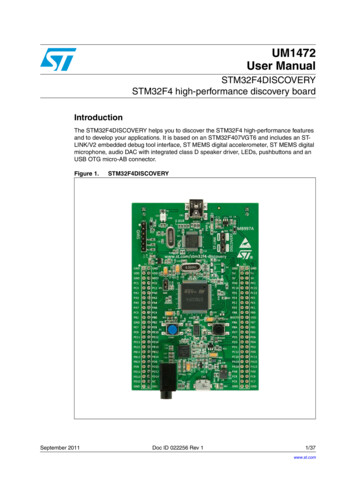
3. In the Manage Run-Time Environment window (Figure 3), you can add microcontroller header andstartup files, device drivers, and other software pack components to the project by checking thecorresponding boxes. (These can also be added later, if desired.)ELEC 2220 - Simple assembly language programs:CMSIS Core and Startup programs are unnecessary for testing simple assembly language programs.Simply click OK, without checking any boxes, to omit these from the project. The assembledprogram code will be placed beginning at the first byte of program memory.For other projects: check the boxes for CMSIS CORE and Device Startup. (CMSIS CortexMicrocontroller Software Interface Standard), plus boxes for any drivers or other softwarecomponents you wish to include in the project. The assembled/compiled code for your programswill be placed after that of the device startup program in program memory. The startup program isrequired for initializing the stack, clocks, and some other system resources, after which it jumps tothe first instruction of your application program.Figure 3. Include the CMSIS CORE and Startup files in the project.(Unless testing simple assembly language programs in ELEC 2220.)
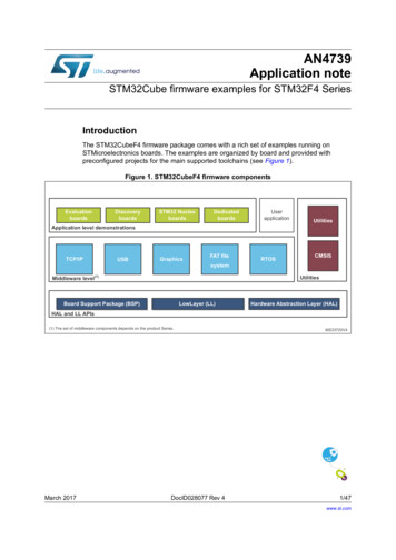
4. Create and add source file(s) to the project in the Project pane of the µVision5 window (Figure 4).You may do this in either or both of the following ways. Right-click on Source Group 1, select Add New Item to Group ‘Source Group 1’, select a file type(C File (.c) or Asm File (.s)), enter the file name (Example: Program1.s), and click Add. Thiscreates a blank file in the editor pane, into which you can type or paste your source program. For files created outside of µVision5, right-click on Source Group 1, select Add Existing Files toGroup ‘Source Group 1’, locate and select file(s) to be added to the project and click Add. Click Close after you’ve created/added all desired source files.DebugOptions for TargetBuildSourceCMSIS &StartupEditor PaneProject PaneBuild Output Pane Figure 4. Add source file(s) to Source Group 1 in the Project pane, and build the project.5. After creating and saving source files, the project must be “built” by compiling/assembling thesource files, correcting any syntax errors as necessary, and then linking the files into onedownloadable program. This is performed by: Click on the Build icon above the project pane (or from the menu bar select Project BuildProject). This will recompile only source file(s) that have changed. OR: Click on the Rebuild icon above the project pane (or from the menu bar select Project Rebuild all target files). This will compile/assemble all source files.NOTE: The project must be rebuilt if you change any device, target, compiler, assembler, or linkeroptions.
6. There are several options for testing and debugging projects with the µVision5 debug tools. Load the program into the simulator for testing, rather than the physical microcontroller (Seeto Step 7 below.) Download the program to the Discovery board, program it into the on-chip flash memory ofthe microcontroller, and execute the program in the target hardware. (See Step 8 below.) Download the program to the Discovery board, place it in the on-chip RAM of the targetmicrocontroller, rather than programming it into flash memory, and execute the program inthe target hardware (See Step 9 below.) Execute a program that was previously programmed into the flash memory of the targetmicrocontroller. (See Step 10 below.)7. To download the compiled program to the simulated microcontroller’s memory and initiate a debugsession with the simulator, set up the project Debug options as follows. From the menu bar, select Project Options for Target ‘Target 1’ (or click on the Options forTarget icon next to the target name in the menu bar.) Select the Debug tab (Figure 5) and check the Use Simulator button. If you wish to use a debug initialization file (described in Step 11 below), enter the file name inthe Initialization File box below the Use Simulator button. Click OK to close the Options for Target window.Figure 5. Target Options Debug tab. “Use Simulator” selected and debug initialization filespecified.
8. To download the compiled program to the Discovery board, program it into the microcontroller’sflash memory, and initiate a debug session, set up the project Debug options as follows. From the menu bar, select Project Options for Target ‘Target 1’ (or click on the Options forTarget icon next to the target name in the menu bar.) Select the Debug tab (Figure 6), check the Use button and select ST-Link Debugger. If you wish to use a debug initialization file (described in Step 11 below), enter the file name inthe Initialization File box below the Use ST-Link Debugger button.Figure 6. Target Options Debug tab. “Use ST-Link Debugger” selected.(Continue on next page for setting up the ST-Link Debugger)
Click on Settings next to ST-Link Debugger to produce the Cortex-M Target Driver SetupWindow (Figure 7), and select Port SW (Single-Wire debug) under Debug Adapter.Figure 7. Single-Wire (SW) Debug Adapter port selected. Click on the Flash Download tab of the Cortex-M Target Driver Setup Window (Figure 8) andunder Programming Algorithm, click the ADD button and select STM32F4xx Flash. Then youcan close the setup and options windows.Figure 8. STM32F4xx flash programming algorithm selected
9. To download the compiled program to the Discovery board, write it into the microcontroller’s onchip RAM instead of flash memory, and initiate a debug session, set up the project Linker and Debugoptions as follows. From the menu bar, select Project Options for Target ‘Target 1’ (or click on the Options forTarget icon next to the target name in the menu bar.) Select the Target tab (Figure 9) and change the Read/Only and Read/Write memory startaddresses and sizes as indicated below, so that the linker will place program code in the lowerhalf of the 128Kbyte on-chip RAM (instead of flash memory), and program data will be placed inthe upper half of the RAM. IROM1: Start 0x20000000, Size 0x10000 (64Kbytes – low half of RAM)(Default IROM1 on Target Tab is 4Mbyte Flash: Start 0x08000000, Size 0x100000) IRAM1: Start 0x20010000, Size 0x10000 (64Kbytes – upper half of RAM)(Default IRAM1 on Target Tab is 128Kbyte RAM: Start 0x20000000, Size 0x20000)Figure 9. Linker instructed to program code (R/O memory) in the lower half of on-chip RAMand data (R/W memory) in the upper half of on-chip RAM. Select the Linker tab, and check the box Use Memory Layout from Target Dialog (Figure 10), sothat the ROM and RAM memory addresses entered in the Target tab are used for read-only andread-write areas.
Figure 10. Check box Use Memory Layout from Target Dialog to use memory addressesentered on the Target tab for the R/O and R/W areas. Select the Asm tab, and in the Define box enter: RAM MODE,REMAPSelect the Debug tab (Figure 6), check the Use button and select ST-Link Debugger, and followthe instructions in Step 8 above for the Cortex-M Target Driver Setup, except on the FlashDownload tab (Figure 11) you must select Do not Erase and uncheck Program and Verify. Thisdisables flash memory programming.Figure 11. Disable flash erase/write/verify for debugging in on-chip RAM
If you wish to use a debug initialization file (described in Step 11 below), enter the file name inthe Initialization File box below the Use ST-Link Debugger button.Click OK to close the Options for Target window.10. To initiate a debug session for a program previously programmed into the microcontroller’s flashmemory on the Discovery board, set up the project Debug options as in Step 8 above, but on theDebug tab (Figure 6), uncheck the button Load Application at Startup, located beneath the Use STLink Debugger button. This will cause the debugger to be entered without downloading theprogram, and therefore use the program currently in the target microcontroller’s flash memory.(Continue with debug session instructions on next page)
11. A debug initialization file is useful to set up any desired initial register and memory values and otherdebug options when the debugger is first opened. This is a plain text file that contains one or moredebugger commands; these commands may also be entered in the Debugger’s Command Window(see Figure 12).The following is a sample initialization file (debug.ini in Figures 5 and 6)xPSR 0x01000000//Set T bit of xPSR Register to Thumb ModePC 0x20000000//Set starting program counter addressE INT 0x20010000 5,23,-100,200,201,-200,0,1000,2000 The first line initializes the T (Thumb) bit to 1 in the Processor Status Register (xPSR) to forcethe processor into Thumb mode. The Cortex-M4 processor in the STM32F407 microcontrollersupports only Thumb mode instructions, and its T bit is hard-wired to 1. However, thesimulator initializes xPSR to all 0’s, thereby setting T 0, which selects ARM mode. Attemptingto execute a Thumb instruction in ARM mode will trigger an error exception. Therefore, theuser must initialize T 1 at the start of simulation.The second line initializes the program counter (PC) to the address of the first instruction to beexecuted. This is useful if no startup code is used and/or if executing programs in RAM mode.The third line enters a sequence of 32-bit data values (separated by commas) into consecutivememory words, beginning at address 0x20010000. The “INT” indicates that the data are to beencoded and written as 32-bit values. Type “CHAR” would indicate 8-bit data. This E commandis useful for entering test data for small programs.12. To initiate a debug session, click the Debug icon in the µVision5 window (Figure 4), or select Debug Start/Stop Debug Session. Depending on how you set up the debug options, this will open theDebug Window (Figure 12) after: downloading the project code to the simulator memory (if set up via Step 7), downloading the project code to the target board and programming it into themicrocontroller’s flash memory (if set up via Step 8), downloading the project code to the target board and writing it to the microcontroller’sRAM (if set up via Step 9), skipping the download (if set up via Step 10)At this point, you may run/stop/step the program, set breakpoints, select watch variables, etc.Click on the Debug icon to stop the debug session and return to the µVision5 IDE.
re 12. MDK uVision5 debug window.Use of the debugger is described in the document Debugging Projects with MDK-ARM, available onthe course web page.For further information, refer to “Keil uVision MDK - uVision Lab for the STM32F4 Discovery Board”(http://www.keil.com/appnotes/docs/apnt 230.asp): App Note 230, Section 20 (Creating your ownproject from scratch)
STM32F4-Discovery Board Projects. Keil Microcontroller Development Kit for ARM (MDK-ARM) Version 5.xx. As illustrated in Figure 1, MDK -ARM Version 5.xx (. µVision5. ) comprises a set of c ore functions: Integrated Development Environment. (IDE) with project manager and editor to create projects . ARM C/C compiler and assembler.