Transcription
ManitowocManitowoc Indigo SeriesIce MachinesInstallation, Use & Care ManualThis manual is updated as new information and models are released.Visit our website for the latest manual. www.manitowocice.comThis manual contains English and French textAmerica’s #1 Selling Ice MachinePart Number 000007345 2/12
Table of ContentsSection 1 General InformationModel Numbers . . . . . . . . . . . . . . . . . . . . . . . . . . . . . . . . . . . . . . . . . . . . . . . . . . . . .Ice Deflector . . . . . . . . . . . . . . . . . . . . . . . . . . . . . . . . . . . . . . . . . . . . . . . . . . .Bin Installation . . . . . . . . . . . . . . . . . . . . . . . . . . . . . . . . . . . . . . . . . . . . . . . . . .Dispenser Installation . . . . . . . . . . . . . . . . . . . . . . . . . . . . . . . . . . . . . . . . . . . .5566Section 2 Installation InstructionsLocation of Ice Machine . . . . . . . . . . . . . . . . . . . . . . . . . . . . . . . . . . . . . . . . . . . . . .Clearance Requirements . . . . . . . . . . . . . . . . . . . . . . . . . . . . . . . . . . . . . . . . . . . . .Ice Machine Heat of Rejection . . . . . . . . . . . . . . . . . . . . . . . . . . . . . . . . . . . . . . . . .Removing Drain Plug and Leveling the Ice Storage Bin . . . . . . . . . . . . . . . . . . . .Air Baffle . . . . . . . . . . . . . . . . . . . . . . . . . . . . . . . . . . . . . . . . . . . . . . . . . . . . . . . . . .Electrical Service . . . . . . . . . . . . . . . . . . . . . . . . . . . . . . . . . . . . . . . . . . . . . . . . . . .Voltage . . . . . . . . . . . . . . . . . . . . . . . . . . . . . . . . . . . . . . . . . . . . . . . . . . . . . . .Fuse/Circuit Breaker . . . . . . . . . . . . . . . . . . . . . . . . . . . . . . . . . . . . . . . . . . . . .Minimum Circuit Ampacity . . . . . . . . . . . . . . . . . . . . . . . . . . . . . . . . . . . . . . . . .Electrical Requirements . . . . . . . . . . . . . . . . . . . . . . . . . . . . . . . . . . . . . . . . . . .Ground Fault Circuit Interrupter . . . . . . . . . . . . . . . . . . . . . . . . . . . . . . . . . . . . .Minimum Power Cord Specifications . . . . . . . . . . . . . . . . . . . . . . . . . . . . . . . . .For United Kingdom Only . . . . . . . . . . . . . . . . . . . . . . . . . . . . . . . . . . . . . . . . .Maximum Breaker Size & Minimum Circuit Amperage Chart . . . . . . . . . . . . . . . .Water Supply and Drain Requirements . . . . . . . . . . . . . . . . . . . . . . . . . . . . . . . . .Water Supply . . . . . . . . . . . . . . . . . . . . . . . . . . . . . . . . . . . . . . . . . . . . . . . . . . .Water Inlet Lines . . . . . . . . . . . . . . . . . . . . . . . . . . . . . . . . . . . . . . . . . . . . . . . .Drain Connections . . . . . . . . . . . . . . . . . . . . . . . . . . . . . . . . . . . . . . . . . . . . . . .Water-Cooled Condenser Water Pressure . . . . . . . . . . . . . . . . . . . . . . . . . . . .Cooling Tower Applications (Water-Cooled Models) . . . . . . . . . . . . . . . . . . . . .Water Supply and Drain Line Sizing/Connections . . . . . . . . . . . . . . . . . . . . . . . .Remote Condenser/Line Set Installation . . . . . . . . . . . . . . . . . . . . . . . . . . . . . . . .Remote Ice Machines Refrigerant Charge . . . . . . . . . . . . . . . . . . . . . . . . . . . .General . . . . . . . . . . . . . . . . . . . . . . . . . . . . . . . . . . . . . . . . . . . . . . . . . . . . . . .Guidelines for Routing Line Sets . . . . . . . . . . . . . . . . . . . . . . . . . . . . . . . . . . . .Calculating Remote Condenser Installation Distances . . . . . . . . . . . . . . . . . . .Lengthening or Reducing Line Set Lengths . . . . . . . . . . . . . . . . . . . . . . . . . . . .Connecting A Line Set . . . . . . . . . . . . . . . . . . . . . . . . . . . . . . . . . . . . . . . . . . . .Remote Receiver Service Valve . . . . . . . . . . . . . . . . . . . . . . . . . . . . . . . . . . . .Remote Ice Machine Usage with Non-Manitowoc Multi-Circuit Condensers . . .Warranty . . . . . . . . . . . . . . . . . . . . . . . . . . . . . . . . . . . . . . . . . . . . . . . . . . . . . .Head Pressure Control Valve . . . . . . . . . . . . . . . . . . . . . . . . . . . . . . . . . . . . . .Fan Motor . . . . . . . . . . . . . . . . . . . . . . . . . . . . . . . . . . . . . . . . . . . . . . . . . . . . .Internal Condenser Volume . . . . . . . . . . . . . . . . . . . . . . . . . . . . . . . . . . . . . . . .Condenser T . . . . . . . . . . . . . . . . . . . . . . . . . . . . . . . . . . . . . . . . . . . . . . . . . .Refrigerant Charge . . . . . . . . . . . . . . . . . . . . . . . . . . . . . . . . . . . . . . . . . . . . . .Quick Connect Fittings . . . . . . . . . . . . . . . . . . . . . . . . . . . . . . . . . . . . . . . . . . . .Non-Manitowoc Multi-Circuit Condenser Sizing Chart . . . . . . . . . . . . . . . . . . . .Installation Check List . . . . . . . . . . . . . . . . . . . . . . . . . . . . . . . . . . . . . . . . . . . . . . .Additional Checks for Remote Models . . . . . . . . . . . . . . . . . . . . . . . . . . . . . . . . . .Before Starting the Ice Machine . . . . . . . . . . . . . . . . . . . . . . . . . . . . . . . . . . . . . . .Set the Time and Date . . . . . . . . . . . . . . . . . . . . . . . . . . . . . . . . . . . . . . . . . . . . . . .Factory Defaults . . . . . . . . . . . . . . . . . . . . . . . . . . . . . . . . . . . . . . . . . . . . . . . . . . . 7171717171717181919192020Part Number 000007345 2/12
Table of Contents (continued)Section 3 OperationControl Panel Features . . . . . . . . . . . . . . . . . . . . . . . . . . . . . . . . . . . . . . . . . . . . . .Buttons . . . . . . . . . . . . . . . . . . . . . . . . . . . . . . . . . . . . . . . . . . . . . . . . . . . . . . .Display Panel . . . . . . . . . . . . . . . . . . . . . . . . . . . . . . . . . . . . . . . . . . . . . . . . . .Overview of Menu Navigation . . . . . . . . . . . . . . . . . . . . . . . . . . . . . . . . . . . . . . . . .Display Panel Navigation . . . . . . . . . . . . . . . . . . . . . . . . . . . . . . . . . . . . . . . . . . . .Alerts and Messages . . . . . . . . . . . . . . . . . . . . . . . . . . . . . . . . . . . . . . . . . . . . . . . .Main Menu . . . . . . . . . . . . . . . . . . . . . . . . . . . . . . . . . . . . . . . . . . . . . . . . . . . . . . . .Machine Info Menu . . . . . . . . . . . . . . . . . . . . . . . . . . . . . . . . . . . . . . . . . . . . . . . . . .Set-Up Menu . . . . . . . . . . . . . . . . . . . . . . . . . . . . . . . . . . . . . . . . . . . . . . . . . . . . . . .Time & Date . . . . . . . . . . . . . . . . . . . . . . . . . . . . . . . . . . . . . . . . . . . . . . . . . . .Time Configuration . . . . . . . . . . . . . . . . . . . . . . . . . . . . . . . . . . . . . . . . . . . . . .Daylight Savings . . . . . . . . . . . . . . . . . . . . . . . . . . . . . . . . . . . . . . . . . . . . . . . .Units . . . . . . . . . . . . . . . . . . . . . . . . . . . . . . . . . . . . . . . . . . . . . . . . . . . . . . . . .Ice Clarity . . . . . . . . . . . . . . . . . . . . . . . . . . . . . . . . . . . . . . . . . . . . . . . . . . . . .LCD Brightness . . . . . . . . . . . . . . . . . . . . . . . . . . . . . . . . . . . . . . . . . . . . . . . . .Factory Defaults . . . . . . . . . . . . . . . . . . . . . . . . . . . . . . . . . . . . . . . . . . . . . . . .LCD On/Off . . . . . . . . . . . . . . . . . . . . . . . . . . . . . . . . . . . . . . . . . . . . . . . . . . . .Clean Minder . . . . . . . . . . . . . . . . . . . . . . . . . . . . . . . . . . . . . . . . . . . . . . . . . . .AuCS Runtime . . . . . . . . . . . . . . . . . . . . . . . . . . . . . . . . . . . . . . . . . . . . . . . . .Air Filter . . . . . . . . . . . . . . . . . . . . . . . . . . . . . . . . . . . . . . . . . . . . . . . . . . . . . . .Water Filter . . . . . . . . . . . . . . . . . . . . . . . . . . . . . . . . . . . . . . . . . . . . . . . . . . . .LuminIce . . . . . . . . . . . . . . . . . . . . . . . . . . . . . . . . . . . . . . . . . . . . . . . . . . . .USB Setup . . . . . . . . . . . . . . . . . . . . . . . . . . . . . . . . . . . . . . . . . . . . . . . . . . . .Language . . . . . . . . . . . . . . . . . . . . . . . . . . . . . . . . . . . . . . . . . . . . . . . . . . . . .Energy Saver Menu . . . . . . . . . . . . . . . . . . . . . . . . . . . . . . . . . . . . . . . . . . . . . . . . .Water Miser . . . . . . . . . . . . . . . . . . . . . . . . . . . . . . . . . . . . . . . . . . . . . . . . . . . .Ice Program . . . . . . . . . . . . . . . . . . . . . . . . . . . . . . . . . . . . . . . . . . . . . . . . . . .Statistics . . . . . . . . . . . . . . . . . . . . . . . . . . . . . . . . . . . . . . . . . . . . . . . . . . . . . .Service Menu . . . . . . . . . . . . . . . . . . . . . . . . . . . . . . . . . . . . . . . . . . . . . . . . . . . . . .Data History . . . . . . . . . . . . . . . . . . . . . . . . . . . . . . . . . . . . . . . . . . . . . . . . . . .RealTime Data . . . . . . . . . . . . . . . . . . . . . . . . . . . . . . . . . . . . . . . . . . . . . . . . .Diagnostics . . . . . . . . . . . . . . . . . . . . . . . . . . . . . . . . . . . . . . . . . . . . . . . . . . . .Manual Harvest . . . . . . . . . . . . . . . . . . . . . . . . . . . . . . . . . . . . . . . . . . . . . . . . .Ice Making Sequence Of Operation . . . . . . . . . . . . . . . . . . . . . . . . . . . . . . . . . . . .Safety Limits . . . . . . . . . . . . . . . . . . . . . . . . . . . . . . . . . . . . . . . . . . . . . . . . . . .Operational Checks . . . . . . . . . . . . . . . . . . . . . . . . . . . . . . . . . . . . . . . . . . . . . . . . .General . . . . . . . . . . . . . . . . . . . . . . . . . . . . . . . . . . . . . . . . . . . . . . . . . . . . . . .Ice Thickness Check . . . . . . . . . . . . . . . . . . . . . . . . . . . . . . . . . . . . . . . . . . . . .Part Number 000007345 2728282828292929292930303131313
Table of Contents (continued)Section 4 MaintenanceCleaning and Sanitizing . . . . . . . . . . . . . . . . . . . . . . . . . . . . . . . . . . . . . . . . . . . . .General . . . . . . . . . . . . . . . . . . . . . . . . . . . . . . . . . . . . . . . . . . . . . . . . . . . . . . .Cleaning/Sanitizing Procedure . . . . . . . . . . . . . . . . . . . . . . . . . . . . . . . . . . . . .Preventative Maintenance Cleaning Procedure . . . . . . . . . . . . . . . . . . . . . . . .Exterior Cleaning . . . . . . . . . . . . . . . . . . . . . . . . . . . . . . . . . . . . . . . . . . . . . . .Cleaning / Sanitizing Procedure . . . . . . . . . . . . . . . . . . . . . . . . . . . . . . . . . . . . . . .Cleaning Procedure . . . . . . . . . . . . . . . . . . . . . . . . . . . . . . . . . . . . . . . . . . . . .Sanitizing Procedure . . . . . . . . . . . . . . . . . . . . . . . . . . . . . . . . . . . . . . . . . . . . .Parts Removal for Cleaning/Sanitizing . . . . . . . . . . . . . . . . . . . . . . . . . . . . . . . . .Preventative Maintenance Cleaning Procedure . . . . . . . . . . . . . . . . . . . . . . . . . .Door Removal . . . . . . . . . . . . . . . . . . . . . . . . . . . . . . . . . . . . . . . . . . . . . . . . . . . . . .Cleaning the Condenser . . . . . . . . . . . . . . . . . . . . . . . . . . . . . . . . . . . . . . . . . . . . .General . . . . . . . . . . . . . . . . . . . . . . . . . . . . . . . . . . . . . . . . . . . . . . . . . . . . . . .Removal from Service/Winterization . . . . . . . . . . . . . . . . . . . . . . . . . . . . . . . . . . .3333333333343435363838393939Checklist . . . . . . . . . . . . . . . . . . . . . . . . . . . . . . . . . . . . . . . . . . . . . . . . . . . . . . . . . .Safety Limit Feature . . . . . . . . . . . . . . . . . . . . . . . . . . . . . . . . . . . . . . . . . . . . . . . . .Commercial Ice Machine Warranty . . . . . . . . . . . . . . . . . . . . . . . . . . . . . . . . . . . .Residential Ice Machine Limited Warranty . . . . . . . . . . . . . . . . . . . . . . . . . . . . . .41424344Section 5 Customer SupportPart Number 000007345 2/124
Section 1General InformationModel Numbers! WarningThis manual covers the following D1892NIY1894N----------------Remove all ice machine panels before lifting andinstalling.ICE DEFLECTORAn ice deflector is required when the ice machine isinstalled on a bin. An ice deflector is not required whenthe ice machine is installed on a dispenser.! WarningManitowoc ice machines require a deflector wheninstalled on an ice storage bin.Prior to using a non-Manitowoc ice storage systemwith Manitowoc ice machines, contact themanufacturer to assure their ice deflector iscompatible with Manitowoc ice machines.! WarningDo not operate equipment that has been misused,abused, neglected, damaged, or altered/modifiedfrom that of original manufactured specifications.This appliance is not intended for use by persons(including children) with reduced physical, sensoryor mental capabilities, or lack of experience andknowledge, unless they have been givensupervision concerning use of the appliance by aperson responsible for their safety.! WarningDo not damage the refrigeration circuit wheninstalling, maintaining or servicing the unit.! WarningDo not use electrical appliances or accessoriesother than those supplied by Manitowoc for your icemachine model.NOTE: Model numbers ending in HP indicate High Pressure water regulatingvalve. Standard pressure 150 psi (10.34 bar) High pressure 350 psi(24.13 bar)Part Number 000007345 2/125
General InformationSection 1BIN INSTALLATIONDISPENSER INSTALLATION All ice machines installed on a bin require an icedeflector. Manitowoc bins have a deflector installed and requireno modifications when used with a forward facingevaporator.No adapter is needed for machines that match thesize of the dispenser unless required by thedispenser manufacturer. 22" & 30" ice machines ship with the deflector/bafflerequired for dispenser usage. No additional deflector/baffle is required, unless specified by the dispensermanufacturer. A bin thermostat to control ice level is recommended. Ice machines with multiple evaporators require adeflector kit.LUMINICE The LuminIce growth inhibitor recirculates the air inthe ice machine foodzone over a UV bulb. This processwill inhibit the growth of common micro-organisms on allexposed foodzone surfaces. LuminIce bulbs require replacement on a yearlybasis. The control board can be set to automatically displaya reminder after 12 months. Refer to LuminIce insection 3 for setup procedures.Cleanup Procedure for Accidental Bulb BreakageThe cleanup procedure is identical to the procedureused to clean up compact fluorescent (CFL) orfluorescent tube lights. These lights contain a smallamount of mercury sealed within a glass tube. Breakingthese types of lights will release mercury and mercuryvapor. The broken bulb can continue to release mercuryvapor until it is cleaned up and removed.CONTROL PANEL BEZELThe ice machine ships with two bezels: The standard bezel allows the display screen to beviewed and the menu, arrows and checkmarkbuttons can be accessed. The key guard bezel allows the display screen to beviewed and covers all buttons to preventunauthorized settings from being entered. The icemachine door must be opened to access the controlpanel.To change the bezel, open the ice machine door, removethe two screws securing the bezel and slide the bezel tothe right while lifting forward.An optional cover that completely hides the display isavailable as a sales kit, and is available through yourlocal distributor or service company.The latest EPA procedures can be viewed on theirwebsite at www.epa.gov/cfl/cflcleanup.html.6Part Number 000007345 2/12
Section 2Installation InstructionsLocation of Ice MachineThe location selected for the ice machine must meet thefollowing criteria. If any of these criteria are not met,select another location. The location must be free of airborne and othercontaminants. The air temperature must be at least 35 F (1.6 C),but must not exceed 110 F (43.4 C). Remote air cooled - The air temperature must be atleast -20 F (-29 C), but must not exceed 120 F(49 C).The location must not be near heat-generatingequipment or in direct sunlight and must be protectedfrom weather.The location must not obstruct air flow through oraround the ice machine. Refer to the clearancerequirement chart.These ice machines are intended for use in householdand similar applications such as: Staff kitchen areas in shops, offices and other workenvironmentsClients in hotels, motels, farmhouses, bed andbreakfast and other residential type environmentsCatering and similar non-retail applicationsClearance Requirements! WarningDo not obstruct ice machine vents or dWater-Cooled*Top/Sides16" (40.6 cm)8" (20.3 cm)Back5" (12.7 cm)5" (12.7 CooledWater-Cooledand Remote*Top/Sides8" (20.3 cm)8" (20.3 cm)Back5" (12.7 cm)5" (12.7 edWater-Cooled*Top/Sides12" (30.5 cm)8" (20.3 cm)Back5" (12.7 cm)5" (12.7 cm)I0500230/50/1 Tropical RatingSelf-Contained Air-CooledTop24" (61.0 cm)Sides/Back12" (30.5 cm)I1200Self-ContainedAir-CooledWater-Cooledand Remote*Top8" (20.3 cm)8" (20.3 cm)Sides12" (30.5 cm)8" (20.3 cm)Back5" (12.7 cm)5" (12.7 and Remote*Top/Sides24" (61.0 cm)8" (20.3 cm)Back12" (30.5 cm)5" (12.7 cm)I3300**Self-Contained Water-CooledTop/Sides8" (20.3 cm)Back24" (61.0 cm)*There is no minimum clearance required for water-cooled orremote ice machines. This value is recommended for efficientoperation and servicing only.** 24” on all sides is recommended to allow access without movingthe bin/ice machine.! CautionThe ice machine must be protected if it will besubjected to temperatures below 32 F (0 C). Failurecaused by exposure to freezing temperatures is notcovered by the warranty.Part Number 000007345 2/127
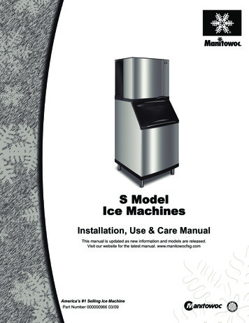
Installation InstructionsIce Machine Heat of RejectionSeriesIce 00I1400I1800I3300Heat of RejectionAir e the heat of rejection varies during the ice making cycle, the figure shown is an average.* Indicates Preliminary DataIce machines, like other refrigeration equipment, rejectheat through the condenser. It is helpful to know theamount of heat rejected by the ice machine when sizingair conditioning equipment where self-contained aircooled ice machines are installed.This information is also necessary when evaluating thebenefits of using water-cooled or remote condensers toreduce air conditioning loads. The amount of heat addedto an air conditioned environment by an ice machineusing a water-cooled or remote condenser is negligible.Knowing the amount of heat rejected is also importantwhen sizing a cooling tower for a water-cooledcondenser. Use the peak figure for sizing the coolingtower.Section 2Removing Drain Plug and Leveling the IceStorage Bin! WarningTo avoid instability the bin/dispenser must beinstalled in an area capable of supporting the weightof the bin/dispenser, ice machine and a full bin ofice. The bin/dispenser must be level side to side andfront to back before installing the ice machine.1. Remove threaded plug from drain fitting.2. Screw the leveling legs onto the bottom of the bin.3. Screw the foot of each leg in as far as possible.! CautionThe legs must be screwed in tightly to prevent themfrom bending.4. Move the bin into its final position.5. Level the bin to assure that the bin door closes andseals properly. Use a level on top of the bin. Turn thebase of each foot as necessary to level the bin.6. Inspect bin gasket prior to ice machine installation.(Manitowoc bins come with a closed cell foamgasket installed along the top surface of the bin.)7. Remove all panels from ice machine before lifting.and installing on bin. Remove both front panels, topcover, left and right side panels.Air BaffleSelf-Contained Air-cooled OnlyThe air-cooled baffle prevents condenser air fromrecirculating. To install:1. Loosen the back panel screws next to thecondenser.2. Align the keyhole slots in the air baffle with the screwholes and slide the baffle down to lock in place.AIRBAFFLE8Part Number 000007345 2/12
Section 2Installation InstructionsElectrical Service! WarningAll wiring must conform to local, state and nationalcodes.VOLTAGEThe maximum allowable voltage variation is 10% of therated voltage at ice machine start-up (when the electricalload is highest).! WarningThe ice machine must be grounded in accordancewith national and local electrical codes.All electrical work, including wire routing and grounding,must conform to local, state and national electricalcodes. The following precautions must be observed: The ice machine must be grounded. A separate fuse/circuit breaker must be provided foreach ice machine. A qualified electrician must determine proper wiresize dependent upon location, materials used andlength of run (minimum circuit ampacity can be usedto help select the wire size). The maximum allowable voltage variation is 10% ofthe rated voltage at ice machine start-up (when theelectrical load is highest). Check all green ground screws in the control box andverify they are tight before starting the ice machine.ImportantObserve correct polarity of incoming line voltage.Incorrect polarity can lead to erratic ice machineoperation.MINIMUM CIRCUIT AMPACITYThe minimum circuit ampacity is used to help select thewire size of the electrical supply. (Minimum circuitampacity is not the ice machine’s running amp load.)The wire size (or gauge) is also dependent uponlocation, materials used, length of run, etc., so it must bedetermined by a qualified electrician.ELECTRICAL REQUIREMENTSRefer to Ice Machine Model/Serial Plate for voltage/amperage specifications.GROUND FAULT CIRCUIT INTERRUPTERGround Fault Circuit Interrupter (GFCI/GFI) protection isa system that shuts down the electric circuit (opens it)when it senses an unexpected loss of power,presumably to ground. Manitowoc Ice does notrecommend the use of a GFCI/GFI circuit protection withour equipment. If code requires the use of a GFCI/GFIthen you must follow the local code. The circuit must bededicated, sized properly and there must be a panelGFCI/GFI breaker. We do not recommend GFCI/GFIoutlets as they are known for more intermittent nuisancetrips than panel breakers.MINIMUM POWER CORD SPECIFICATIONSMaximumBreaker Size15 amp20 amp30 amp40 ampMinimumWire Size14 gauge12 gauge10 gauge8 gaugeMaximum Length ofPower Cord6 feet (1.83 m)6 feet (1.83 m)6 feet (1.83 m)6 feet (1.83 m)If a power cord is used, the wire size to the receptacle isdependent upon location, materials used, length of run,etc., so it must be determined by a qualified electrician.Local, state or national requirements will supersede ourminimum requirements.FOR UNITED KINGDOM ONLYFUSE/CIRCUIT BREAKERA separate fuse/circuit breaker must be provided foreach ice machine. Circuit breakers must be H.A.C.R.rated (does not apply in Canada).Part Number 000007345 2/12As the colors of the wires in the mains lead of the appliance may notcorrespond with the colored markings identifying the terminals in your plug,proceed as follows: The wire which is colored green and yellow must be connected to theterminal in the plug which is marked with the letter E or by the earthor colored green or green and yellow.ground symbol The wire colored blue must be connected to the terminal which is markedwith the letter N or colored black. The wire colored brown must be connected to the terminal which ismarked with the letter L or colored red.9
Installation InstructionsSection 2Maximum Breaker Size & Minimum Circuit Amperage ChartImportantImportantDue to continuous improvements, this information is for reference only.Please refer to the ice machine serial number tag to verify electrical data.Serial tag information overrides information listed on this page. I3300 Only - Verify the direction of rotation is correct on the 3ph scrollcompressor. The ice machine will have high suction pressure, lowdischarge pressure and will be noticeably loud. Reverse any two incomingpower leads to reverse rotation.Ice itCircuit ter CooledMaximumMinimumFuse/CircuitCircuit eMaximumMinimumFuse/CircuitCircuit 40*23.425*15.040*21.5N/AN/AN/AN/AN/AN/AN/AN/A* Preliminary Data, Subject to change10Part Number 000007345 2/12
Section 2Installation InstructionsWater Supply and Drain RequirementsWATER SUPPLYWATER-COOLED CONDENSER WATER PRESSURELocal water conditions may require treatment of thewater to inhibit scale formation, filter sediment, andremove chlorine odor and taste.Water pressure at the condenser cannot exceed 150psig (1034 kPa) with the standard water-regulatingvalve. Contact your distributor if your water pressure isgreater than 150 psig (1034 kPa). A special ordercondensing unit is available that allows water pressureup to 350 psig (2413 kPa)! WarningConnect to a potable water supply only.COOLING TOWER APPLICATIONS(WATER-COOLED MODELS)WATER INLET LINESFollow these guidelines to install water inlet lines: If you are installing a Manitowoc Arctic Pure waterfilter system, refer to the Installation Instructionssupplied with the filter system for ice making waterinlet connections.Do not connect the ice machine to a hot watersupply. Be sure all hot water restrictors installed forother equipment are working. (Check valves on sinkfaucets, dishwashers, etc.)If water pressure exceeds the maximumrecommended pressure of 80 psi (552 kPa), obtain awater pressure regulator from your Manitowocdistributor. Install a water shut-off valve for both the ice makingand condenser water lines. Insulate water inlet lines to prevent condensation.! CautionDo not apply heat to water valve inlet fitting. This willdamage plastic water inlet connection.DRAIN CONNECTIONSA water cooling tower installation does not requiremodification of the ice machine. The water regulatorvalve for the condenser continues to control therefrigeration discharge pressure.It is necessary to know the amount of heat rejection, andthe pressure drop through the condenser and watervalves (inlet and outlet) when using a cooling tower onan ice machine. Water entering the condenser must not exceed90 F (32 C). Water flow through the condenser must not exceed5 gallons (19 liters) per minute. Allow for a pressure drop of 7 psi (50 kPa) betweenthe condenser water inlet and the outlet of the icemachine. Water exiting the condenser must not exceed110 F (43 C).ImportantThe Commonwealth of Massachusetts requires thatall water-cooled models must be connected only to aclosed loop, cooling tower system.Follow these guidelines when installing drain lines toprevent drain water from flowing back into the icemachine and storage bin: Drain lines must have a 1.5 inch drop per 5 feet ofrun (2.5 cm per meter), and must not create traps. The floor drain must be large enough toaccommodate drainage from all drains. Run separate bin and ice machine drain lines.Insulate them to prevent condensation. Vent the bin and ice machine drain to theatmosphere. Do not vent the condenser drain onwater-cooled models.Part Number 000007345 2/1211
Installation InstructionsSection 2Water Supply and Drain Line Sizing/Connections! CautionPlumbing must conform to state and local codes.WaterTemperatureWater PressureIce Machine FittingTubing Size Up to IceMachine Fitting35 F (2 C) Min.90 F (32 C) Max.20 psi (140 kPa) Min.80 psi (552 kPa) Max.3/8" (.95 cm) Female Pipe Thread1/2" (1.27 cm) FPT I3300 Only3/8" (.95 cm) min inside diameter------1/2" (1.27 cm) Female Pipe Thread1/2" (1.27 cm) min inside diameterCondenserWater Inlet90 F (32.2 C) Max.Standard20 psi (140 kPa) Min.150 psi (1034 kPa) Max.High Pressure Option20 psi (140 kPa) Min.350 psi (2410 kPa) Max.CondenserWater Drain------1/2" (1.27 cm) Female Pipe Thread1/2" (1.27 cm) min inside diameterBin Dr
provided by Manitowoc Ice. Performance may vary from Sales specifications. ARI certified standard ratings only apply when used with a Manitowoc remote condenser. If the design of the condenser meets the specifications, Manitowoc's only approval is for full warranty coverage to be extended to the Manitowoc manufactured part of the system.