Transcription
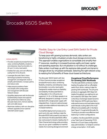
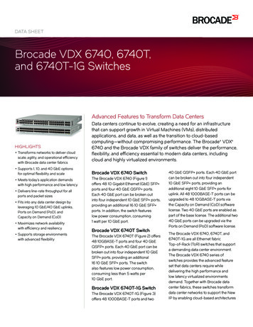
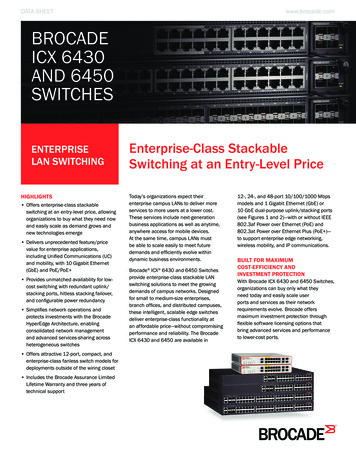
Se n d d o c u m e n t a t i o n c o m m e n t s t o m d s f e e d b a ck - d o c @ c i s c o . c o mCH A P T E R6MDS 9000 Core with Brocade 3900/12000 EdgeTopologyThis chapter describes how to set up a basic core-edge topology with one MDS 9000 switch configuredfor interop mode 1 at the core and two Brocade switches at the edge. All devices are connected to theedge switches. However, all traffic must flow through the core switch to reach its destination.This chapter includes the following sections: Specifications, page 6-1 Expected Topology Behavior, page 6-2 Configuration, page 6-3 Verification, page 6-6 Zoning, page 6-15SpecificationsThe following switches and code levels were used for this example configuration: MDS 9216 running MDS SAN-OS Release 1.1(1) Brocade 3900 Version 04.0.2d Brocade 12000 Version 4.0.2cFigure 6-1 shows the topology used for this example configuration.Cisco MDS 9000 Family Switch-to-Switch Interoperability Configuration GuideOL-8400-026-1
Chapter 6MDS 9000 Core with Brocade 3900/12000 Edge TopologyExpected Topology BehaviorSe n d d o c u m e n t a t i o n c o m m e n t s t o m d s f e e d b a ck - d o c @ c i s c o . c o mFigure 6-1MDS 9000 Switch Core Switch with Brocade 3900 and 12000 Edge Switch TopologyExpected Topology BehaviorThis section covers the Fibre Channel services and features that act differently in this topology(Figure 6-1) as compared to a homogeneous, single-vendor implementation.This section contains the following topics: Zoning, page 6-2 FSPF, page 6-3 Trunking and PortChannels, page 6-3 Domain IDs, page 6-3ZoningIn the core-edge topology (using standard interop mode), zone members are all pWWNs because theBrocade domain/port nomenclature is not a valid form according to the FC standard. When a zone set(or configuration, in Brocade terminology) activation is made at the core switch, the zone set activationreaches all switches at the same time because they are all the same distance from the core.The Brocade edge switches provide all of the zone security because the MDS 9000 switch does not checkthe source and destination of the frame when traversing E ports. Brocade switches only check the zoninginformation on the egress port of the fabric.NoteAfter two active zone sets successfully merge, always copy the active zone set to the full zone setdatabase prior to modifying it on the MDS 9000 switch.Cisco MDS 9000 Family Switch-to-Switch Interoperability Configuration Guide6-2OL-8400-02
Chapter 6MDS 9000 Core with Brocade 3900/12000 Edge TopologyConfigurationSe n d d o c u m e n t a t i o n c o m m e n t s t o m d s f e e d b a ck - d o c @ c i s c o . c o mFSPFAll links within the topology show the link cost of 500.Because the Brocade switches load balance their routes using source and destination, the ingress edgeswitch uses the same core switch for all traffic that has the same source and destination pair. If theBrocade switch could load balance using source/destination/ox-id, then it could choose either of the twocore switches for the route through the fabric.Trunking and PortChannelsThe lack of MDS 9000 switch-to-MDS 9000-switch connections prohibits the topology from containingTE ports or PortChannels. While in interop mode, the Brocade switches do not support trunked ports ofany type. Only standard E ports are used for the ISLs.Domain IDsThe domain IDs are limited to the 97 to 127 range due to a restriction imposed by McData's inability tohandle IDs outside of that range. While Brocade switches and MDS 9000 switches can handle domainIDs outside of this range, their implementation of interoperability mode includes this limitation.Domain ID modifications can be handled in two ways, disruptively or nondisruptively: Disruptive—This event impacts the entire switch. When changing domain IDs, Brocade requiresthe entire switch to be taken offline and/or rebooted. Nondisruptive—This event is limited to the VSAN where the event is taking place. Only theMDS 9000 switch can perform this action, as the domain manager process for this VSAN is restartedand not the entire switch. This restart requires any device logged into the VSAN to log into the fabricagain to obtain a new FC ID.ConfigurationThis section describes the configuration process and includes the following topics: Configuring the MDS 9000 Switch, page 6-3 Configuring the Brocade 3900 Switch, page 6-4 Configuring the Brocade 12000 Switch, page 6-5Configuring the MDS 9000 SwitchFollow these steps to configure the MDS 9000 switch.Step 1Place the VSAN of the E ports(s) that connect to the OEM switch in interoperability mode.MDS9000# config tMDS9000(config)# vsan databaseMDS9000(config-vsan-db)# vsan 1 interopCisco MDS 9000 Family Switch-to-Switch Interoperability Configuration GuideOL-8400-026-3
Chapter 6MDS 9000 Core with Brocade 3900/12000 Edge TopologyConfigurationSe n d d o c u m e n t a t i o n c o m m e n t s t o m d s f e e d b a ck - d o c @ c i s c o . c o mStep 2Assign a domain ID in the range of 97 (0x61) through 127 (0x7F). This interop mode limitation restrictsthe fabric to a total of 31 switches.In the MDS 9000 switch, the default is to request an ID from the principal switch. If the preferredkeyword is used, the MDS 9000 switch requests a specific ID, but still joins the fabric if the principalswitch assigns a different ID. If the static keyword is used, the MDS 9000 switch will not join the fabricunless the principal switch agrees, and assigns the requested ID.MDS9000# config tMDS9000(config)# fcdomain domain 120 preferred vsan 1Step 3Change the Fibre Channel timers if they have been changed from the system defaults. The FC errorDetect (ED TOV) and Resource Allocation (RA TOV) timers on the MDS 9000 switch and Brocadeswitches default to the same values. The RA TOV defaults to 10 seconds, and the ED TOV defaults to2 seconds. These values can be changed. According to the FC-SW2 standard, these values must be thesame on each switch in the fabric.MDS9000# config tMDS9000(config)# fctimer e d tov ? 1000-100000 E D TOV in milliseconds(1000-100000)MDS9000(config)# fctimer r a tov ? 5000-100000 R A TOV in milliseconds(5000-100000)Step 4After making changes to the domain, restart the MDS 9000 switch domain manager function for thealtered VSAN. To do this, suspend and then resume the VSAN.MDS9509(config)# vsan databaseMDS9509(config-vsan-db)# vsan 1 suspendMDS9509(config-vsan-db)# no vsan 1 suspendConfiguring the Brocade 3900 SwitchFollow these steps to configure the Brocade 3900 switch in interoperability mode.Step 1Disable the switch. This is a disruptive process.CA3900:admin switchdisableStep 2Enter the configuration dialog.CA3900:admin configureConfigure.Fabric parameters (yes, y, no, n): [no] yDomain: (97.239) [98] 98 Assign domain id in the 97-127 rangeR A TOV: (4000.120000) [10000] Must match other switches in the fabricE D TOV: (1000.5000) [2000] Must match other switches in the fabricData field size: (256.2112) [2112]Sequence Level Switching: (0.1) [0]Disable Device Probing: (0.1) [0]Suppress Class F Traffic: (0.1) [0]VC Encoded Address Mode: (0.1) [0]Per-frame Route Priority: (0.1) [0]BB credit: (1.16) [16]Cisco MDS 9000 Family Switch-to-Switch Interoperability Configuration Guide6-4OL-8400-02
Chapter 6MDS 9000 Core with Brocade 3900/12000 Edge TopologyConfigurationSe n d d o c u m e n t a t i o n c o m m e n t s t o m d s f e e d b a ck - d o c @ c i s c o . c o mVirtual Channel parameters (yes, y, no, n): [no]Zoning Operation parameters (yes, y, no, n): [no]RSCN Transmission Mode (yes, y, no, n): [no]NS Operation Parameters (yes, y, no, n): [no]Arbitrated Loop parameters (yes, y, no, n): [no]System services (yes, y, no, n): [no]Portlog events enable (yes, y, no, n): [no]Step 3Disable platform management services. Failure to do this will isolate any E ports that connect tonon-Brocade switches.CA3900:admin msPlMgmtDeactivateThis will erase all Platform entries. Are you sure? (yes, y, no, n): [no] yCommitting configuration.done.Request Fabric to Deactivate Platform Management services.Done.Step 4Configure interoperability mode, and then reboot.CA3900:admin interopmode 1 Set interop mode onCommitting configuration.done.interopMode is 1NOTE: It is recommended that you reboot the switch to make this change take effectNoteDo not ignore the warning message. Anomalies were experienced that required a switch reboot.CA3900:admin fastbootTo return to non-interop mode, you must disable the switch. Reconfigure the switch, set theinteroperability mode to 0, and then reboot.Configuring the Brocade 12000 SwitchFollow these steps to configure the Brocade 12000 switch in interoperability mode.Step 1Disable the switch. This is a disruptive process.CA12000:admin switchdisableStep 2Enter the configuration dialog.CA12000:admin configureConfigure.Fabric parameters (yes, y, no, n): [no] yDomain: (97.239) [110] 110 Assign domain id in the 97-127 rangeR A TOV: (4000.120000) [10000] Must match other switches in the fabricE D TOV: (1000.5000) [2000] Must match other switches in the fabricData field size: (256.2112) [2112]Sequence Level Switching: (0.1) [0]Disable Device Probing: (0.1) [0]Suppress Class F Traffic: (0.1) [0]Cisco MDS 9000 Family Switch-to-Switch Interoperability Configuration GuideOL-8400-026-5
Chapter 6MDS 9000 Core with Brocade 3900/12000 Edge TopologyVerificationSe n d d o c u m e n t a t i o n c o m m e n t s t o m d s f e e d b a ck - d o c @ c i s c o . c o mVC Encoded Address Mode: (0.1) [0]Per-frame Route Priority: (0.1) [0]BB credit: (1.16) [16]Virtual Channel parameters (yes, y, no, n): [noZoning Operation parameters (yes, y, no, n): [nRSCN Transmission Mode (yes, y, no, n): [no]NS Operation Parameters (yes, y, no, n): [no]Arbitrated Loop parameters (yes, y, no, n): [noSystem services (yes, y, no, n): [no]Portlog events enable (yes, y, no, n): [no]Step 3Disable platform management services. Failure to do this will isolate E ports that connect tonon-Brocade switches.CA12000:admin msPlMgmtDeactivateThis will erase all Platform entries. Are you sure? (yes, y, no, n): [no] yCommitting configuration.done.Request Fabric to Deactivate Platform Management services.Done.Step 4Configure interoperability mode at the command line, and then reboot.CA12000:admin interopmode 1 Set interop mode onCommitting configuration.done.interopMode is 1NOTE: It is recommended that you boot this switch to make this change take effectNoteDo not ignore the above warning message. Anomalies were experienced that required a switch reboot.CA12000:admin fastbootTo return to non-interop mode, disable the switch. Reconfigure the switch, set interoperability mode to0, and then reboot.VerificationThe following section highlights the commands used to verify that the fabric is up and running ininteroperability mode.In this example topology, there are only single ISLs. If there were multiple ISLs connecting the edgeBrocade switches to the core MDS 9000 switch, the Brocade switches would load balance their routesusing source and destination, and the ingress edge switch would use the same ISL for all traffic that hasthe same source and destination pair. The MDS 9000 switch would continue to load balance across ISLsusing the source/destination/ox-id of the frame. This principle is illustrated in Figure 5-12.Cisco MDS 9000 Family Switch-to-Switch Interoperability Configuration Guide6-6OL-8400-02
Chapter 6MDS 9000 Core with Brocade 3900/12000 Edge TopologyVerificationSe n d d o c u m e n t a t i o n c o m m e n t s t o m d s f e e d b a ck - d o c @ c i s c o . c o mVerifying the MDS 9000 SwitchThe following examples show verification of the MDS 9000 switch.MDS9000# show versionCisco Storage Area Networking Operating System (SAN-OS) SoftwareTAC support: http://www.cisco.com/tacCopyright (c) 2002-2003 by Cisco Systems, Inc. All rights reserved.The copyright for certain works contained herein are owned byAndiamo Systems, Inc. and/or other third parties and are used anddistributed under onversionversionversion1.0.71.0(3a) [last : 1.0(4)]1.1(1)1.1(1)BIOS compile time:kickstart image file is:kickstart compile time:system image file is:system compile .1.bin5/23/2003 0:00:00bootflash:/m9200-ek9-mz.1.1.1.bin5/23/2003 0:00:00HardwareRAM 963116 kBbootflash: 500736 blocks (block size 512b)slot0:0 blocks (block size 512b)MDS9000 uptime is 1 days 21 hours 38 minute(s) 3 second(s)Last reset at 412363 usecs after Wed Jul 2 02:40:38 2003Reason: Reset Requested by management applicationSystem version: 1.1(1)MDS9000# show interface ------------------------------Interface VsanAdmin AdminStatusOper OperPort-channelModeTrunkMode co MDS 9000 Family Switch-to-Switch Interoperability Configuration GuideOL-8400-026-7
Chapter 6MDS 9000 Core with Brocade 3900/12000 Edge TopologyVerificationSe n d d o c u m e n t a t i o n c o m m e n t s t o m d s f e e d b a ck - d o c @ c i s c o . c o ------------InterfaceStatusIP .22.36.255/23 100 ---------------------------------InterfaceStatusIP ----------------------------------------vsan1up-1 Gbps1500MDS9000# show running-configBuilding Configuration .vsan databasevsan 1 interopinterface vsan1snmp-server community public rwsnmp-server user admin network-admin auth md5 server host 10.10.3.20 traps version 1 publicsnmp-server host 171.69.122.33 traps version 2c public udp-port 2162snmp-server host 171.71.188.65 traps version 2c public udp-port 4058boot system bootflash:/m9200-ek9-mz.1.1.1.binboot kickstart bootflash:/m9200-ek9-kickstart-mz.1.1.1.binip default-gatewaykernel core modulekernel core modulekernel core modulekernel core modulekernel core modulekernel core modulekernel core modulekernel core modulekernel core modulekernel core modulekernel core modulekernel core modulekernel core modulekernel core modulekernel core module172.22.36.11 level ram2 level ram3 level ram4 level ram5 level ram6 level ram7 level ram8 level ram9 level ram10 level ram11 level ram12 level ram13 level ram14 level ram15 level ramswitchname MDS9000username admin password 5 AOpL5dCXKyzngzone name Bro12000 vsan 1member pwwn 21:01:00:e0:8b:29:8b:3emember pwwn 21:00:00:e0:8b:09:8b:3emember pwwn 50:06:0e:80:03:4e:95:32role network-adminCisco MDS 9000 Family Switch-to-Switch Interoperability Configuration Guide6-8OL-8400-02
Chapter 6MDS 9000 Core with Brocade 3900/12000 Edge TopologyVerificationSe n d d o c u m e n t a t i o n c o m m e n t s t o m d s f e e d b a ck - d o c @ c i s c o . c o mzone default-zone permit vsan 2-4zoneset name BrocadeZoneSet vsan 1member Bro12000zonesetactivate name BrocadeZoneSet vsan 1interface fc1/1no shutdowninterface fc1/2no shutdowninterface fc1/3interface fc1/4interface fc1/5interface fc1/6interface fc1/7interface fc1/8interface fc1/9interface fc1/10interface fc1/11interface fc1/12interface fc1/13interface fc1/14interface fc1/15no shutdowninterface fc1/16switchport mode Eno shutdowninterface mgmt0ip address 172.22.36.255 255.255.254.0Cisco MDS 9000 Family Switch-to-Switch Interoperability Configuration GuideOL-8400-026-9
Chapter 6MDS 9000 Core with Brocade 3900/12000 Edge TopologyVerificationSe n d d o c u m e n t a t i o n c o m m e n t s t o m d s f e e d b a ck - d o c @ c i s c o . c o mMDS9000# show vsan 1vsan 1 informationname:VSAN0001 state:activeinteroperability l state:upMDS9000# show fcdomain vsan 1The local switch is a Subordinated Switch.Local switch run time information:State: StableLocal switch WWN:20:01:00:05:30:00:68:5fRunning fabric name: 10:00:00:60:69:90:08:2fRunning priority: 128Current domain ID: 0x78(120) Verify domain idLocal switch configuration information:State: EnabledFCID persistence: DisabledAuto-reconfiguration: DisabledContiguous-allocation: DisabledConfigured fabric name: 20:01:00:05:30:00:28:dfConfigured priority: 128Configured domain ID: 0x00(0) (preferred)Principal switch run time information:Running priority: S9000# show fcdomain domain-list vsan 1Number of domains: 3Domain 0:60:69:90:08:2f [Principal] Brocade 39000x6e(110)10:00:00:60:69:80:1d:cf Brocade 120000x78(120)20:01:00:05:30:00:68:5f [Local] MDS9216MDS9000# show fspf internal route vsan 1FSPF Unicast Routes--------------------------VSAN Number Dest DomainRoute CostNext 10x62(98)500fc1/1510x6e(110)500fc1/16MDS9000# show fspf internal route vsan 1FSPF Unicast Routes--------------------------VSAN Number Dest DomainRoute CostNext 10x62(98)500fc1/1510x6e(110)500fc1/16Cisco MDS 9000 Family Switch-to-Switch Interoperability Configuration Guide6-10OL-8400-02
Chapter 6MDS 9000 Core with Brocade 3900/12000 Edge TopologyVerificationSe n d d o c u m e n t a t i o n c o m m e n t s t o m d s f e e d b a ck - d o c @ c i s c o . c o mMDS9000# show fcns database vsan 1VSAN -------------------------FCIDTYPE -0x621c00N21:01:00:e0:8b:29:8b:3e (QLogic)0x621d00N21:00:00:e0:8b:09:8b:3e tal number of entries 3NoteThe MDS name server shows both local and remote entries, and it does not time out the entries.Verifying the Brocade 3900 SwitchThe following examples show verification of the Brocade 3900 switch.CA3900:admin versionKernel:2.4.2Fabric OS: v4.0.2dMade on:Sat Apr 5 00:22:58 2003Flash:Mon Jun 23 18:49:49 2003BootProm:3.1.18CA3900:admin licenseshowedcczbyc9pedd0X:Web licenseZoning licenseFabric licenseFabric Watch licenseTrunking licenseCA3900:admin eacon:OFFPort Gbic Speed State 0-N2No Module1-N2No Module2-N2No Module3-N2No Module4-N2No Module5-N2No Module6-N2No Module7-N2No Module8-N2No Module9-N2No Module10-N2No Module11-N2No Module12-N2No Module13-N2No ModuleCisco MDS 9000 Family Switch-to-Switch Interoperability Configuration GuideOL-8400-026-11
Chapter 6MDS 9000 Core with Brocade 3900/12000 Edge TopologyVerificationSe n d d o c u m e n t a t i o n c o m m e n t s t o m d s f e e d b a ck - d o c @ c i s c o . c o ---ididididN2N2N2N2N2N2N2N2N2N2N2N2N2N2N2N2N2N2No ModuleNo LightOnlineE-PortNo ModuleNo ModuleNo ModuleNo ModuleNo ModuleNo ModuleNo ModuleNo ModuleNo ModuleNo ModuleNo ModuleOnlineF-PortOnlineF-PortNo LightNo Light20:01:00:05:30:00:68:5f 09:8b:3eCA3900:admin topologyshow3 domains in the fabric; Local Domain ID: 98Domain:Metric:Name:Path Count:1101000CA120001Hops:Out Port:In Ports:Total Bandwidth:Bandwidth Demand:Flags:Domain:Metric:Name:Path Count:21628 292 Gbps200 %D120500Unknown1Hops:Out Port:In Ports:Total Bandwidth:Bandwidth Demand:Flags:11628 292 Gbps200 %DCA3900:admin interopmodeInteropMode: OnUsage: InteropMode 0 10: to turn it off1: to turn it onCA3900:admin nsallshow3 Nx Ports in the Fabric {621c00 621d00 6e0e00}NoteThe Brocade switch remote name server entries time out of the cache after 900 seconds (15 minutes).Cisco MDS 9000 Family Switch-to-Switch Interoperability Configuration Guide6-12OL-8400-02
Chapter 6MDS 9000 Core with Brocade 3900/12000 Edge TopologyVerificationSe n d d o c u m e n t a t i o n c o m m e n t s t o m d s f e e d b a ck - d o c @ c i s c o . c o mCA3900:admin urouteshowLocal Domain ID: 98In PortDomainOut PortMetricHopsFlagsNext (Dom, 50120165001D120,65550Verifying the Brocade 12000 SwitchThe following examples show the commands used to verify the configuration of the Brocade 12000switch.CA12000:admin versionKernel:2.4.2Fabric OS: v4.0.2cMade on:Wed Jan 22 04:17:49 2003Flash:Thu Mar 20 23:48:04 2003BootProm:3.1.18CA12000:admin licenseshowSQeRRcyyRzdRfSSz:Web licenseZoning licenseFabric Watch licenseTrunking licenseRzb9SzQc99S0cATc:Fabric licenseCA12000:admin tchBeacon:OFFblade7 Beacon: OFFArea Slot Port Gbic Speed State 070idN2No Light171idN2No Light272idN2No Light373idN2No Light474idN2No Light575idN2No Light676idN2No Light777idN2No Light878idN2No Light979idN2No Light10710idN2No Light11711idN2No Light12712idN2No Light13713idN2No 06:0e:80:03:4e:95:3220:01:00:05:30:00:68:5f (upstream)Cisco MDS 9000 Family Switch-to-Switch Interoperability Configuration GuideOL-8400-026-13
Chapter 6MDS 9000 Core with Brocade 3900/12000 Edge TopologyVerificationSe n d d o c u m e n t a t i o n c o m m e n t s t o m d s f e e d b a ck - d o c @ c i s c o . c o mCA12000:admin topologyshow3 domains in the fabric; Local Domain ID: 110Domain:Metric:Name:Path Count:981000CA39001Hops:Out Port:In Ports:Total Bandwidth:Bandwidth Demand:Flags:Domain:Metric:Name:Path Count:27/157/142 Gbps100 %D120500Unknown1Hops:Out Port:In Ports:Total Bandwidth:Bandwidth Demand:Flags:17/157/142 Gbps100 %DCA12000:admin interopmodeInteropMode: OnUsage: InteropMode 0 10: to turn it off1: to turn it onCA12000:admin nsshowThe Local Name Server has 1 entry {Type 0:03:4e:95:32;50:06:0e:80:03:4e:95:32; naFC4s: FCP [HITACHI OPEN-32105]Fabric Port Name: 20:0e:00:60:69:80:1d:cf}CA12000:admin nsallshow3 Nx Ports in the Fabric {621c00 621d00 6e0e00}NoteThe Brocade switch remote name server entries time out of the cache after 900 seconds (15 minutes).CA12000:admin urouteshowLocal Domain ID: 110In PortDomainOut PortMetricHopsFlagsNext (Dom, 1120155001D120,65551Cisco MDS 9000 Family Switch-to-Switch Interoperability Configuration Guide6-14OL-8400-02
Chapter 6MDS 9000 Core with Brocade 3900/12000 Edge TopologyZoningSe n d d o c u m e n t a t i o n c o m m e n t s t o m d s f e e d b a ck - d o c @ c i s c o . c o mZoningIn this example, the zone is created on the MDS 9000 switch and the zone set is activated. Afteractivation, the verification process confirms that the Brocade switches properly learn the zones and zonesets. In Brocade terminology, the zone set is known as the configuration. On Brocade switches, the MDS9000 active zone set is known as the effective configuration.The example shows how to use the name server database as a tool when building the zones. Whenpredefining zones, you may use pWWNs of equipment not attached, or in the name server database.Zones that are defined while the switch is in interop mode must be zoned by pWWN. Zoning by alias orFC ID is not permitted while the Brocade switch is operating in interop mode. This limits the Brocadeswitches to soft zoning. The MDS 9000 switch will always implement hardware-enforced zoning.Creating Zones on the MDS 9000 SwitchFollow these steps to create zones on the MDS 9000 switch.Step 1Display the name server database to see the pWWN information.MDS9000# show fcns database vsan 1VSAN -------------------------FCIDTYPE -0x621c00N21:01:00:e0:8b:29:8b:3e (QLogic)0x621d00N21:00:00:e0:8b:09:8b:3e tal number of entries 3Step 2Now that the pWWNs are visible, use tools like cut and paste to create the zones.MDS9000# conf tEnter configuration commands, one per line.MDS9000(config)# 000(config-zone)#End with CNTL/Z.name Bro12000 vsan 1member pwwn 21:01:00:e0:8b:29:8b:3emember pwwn 21:00:00:e0:8b:09:8b:3emember pwwn fig)# zoneset name BrocadezoneSet vsan 1MDS9000(config-zoneset)# member Bro12000At this point, we have created one zone (Bro12000) within the zone set named BrocadeZoneSet.Step 3Activate the zone set BrocadeZoneSet.MDS9000(config)# zoneset activate name BrocadeZoneSet vsan 1Zoneset Activation initiated. check zone statusMDS9000(config)# exitStep 4View each switch in the fabric to verify that the defined zoning is in place. The running config will showthe zone and zone set, because they were created on this switch.MDS9000# show zoneset active vsan 1zoneset name BrocadeZoneSet vsan 1Cisco MDS 9000 Family Switch-to-Switch Interoperability Configuration GuideOL-8400-026-15
Chapter 6MDS 9000 Core with Brocade 3900/12000 Edge TopologyZoningSe n d d o c u m e n t a t i o n c o m m e n t s t o m d s f e e d b a ck - d o c @ c i s c o . c o mzone name Bro12000 vsan 1* fcid 0x621c00 [pwwn 21:01:00:e0:8b:29:8b:3e]* fcid 0x621d00 [pwwn 21:00:00:e0:8b:09:8b:3e]* fcid 0x6e0e00 [pwwn 50:06:0e:80:03:4e:95:32]Verifying Zoning on the Brocade 12000 SwitchThe Brocade 12000 switch does not have a defined configuration, but it does contain an effectiveconfiguration. The effective configuration was passed to it by the MDS 9000 switch when the MDS 9000switch full zone set was activated.CA12000:admin cfgshowDefined configuration:no configuration definedEffective configuration:cfg:BrocadeZoneSetzone: b:3e50:06:0e:80:03:4e:95:32Verifying Zoning on the Brocade 3900 SwitchThe following example shows commands used to verify the configuration of the Brocade 3900 switch.CA3900:admin cfgshowDefined configuration:no configuration definedEffective configuration:cfg:BrocadeZoneSetzone: b:3e50:06:0e:80:03:4e:95:32NoteThe zones created in the MDS 9000 switch are propagated to the Brocade switches. Although thecfgshow command does not show these zones as the defined configuration, if the switch is isolated andrebooted, the correct zone configuration is effective.On the MDS 9000 switch, the active zone configuration is always saved to memory. It will not displayin the running configuration. If the switch is isolated and rebooted, the last active zone set is reinstatedas the current active zone set.Any changes to the zones or zone set while the switch is isolated will need to pass a zone mergevalidation when the ISLs are activated.Cisco MDS 9000 Family Switch-to-Switch Interoperability Configuration Guide6-16OL-8400-02
When changing domain IDs, Brocade requires the entire switch to be taken offline and/or rebooted. † Nondisruptive—This event is limited to the VSAN where the event is taking place. Only the MDS 9000 switch can perform this action, as the do main manager process for this VSAN is restarted and not the entire switch.