Transcription
Network Drafting for Double WeaveIntroductionAt Convergence 1992 in Washington D.C. Alice Schlein and I both presented seminars. Ihad just published my book “Loom Controlled Double Weave” and thought that I understooddouble weave rather well. That is, until I heard Alice’s presentation on network drafting!Among her many beautiful and mysterious samples was a group in double weave and Irealized there was still a fair amount about double weave that I needed to ponder.That started me on a rather lengthy program of trying to “get a handle on” what happenswhen the principles of network drafting are applied to double weave. Along the way Iwandered down some different paths for a while (four double weave blocks with an 8 shaftloom; eight double weave blocks with an 8 shaft loom; dividing and recombining the twobasic tieups of double weave which leads to integrated double weave) and it is only now thatI see how those different paths interrelate with network drafting. Alice Schlein’s book“Network Drafting: an Introduction” published in 1994, along with her articles in Weaver’smagazine, provided both an inspiration and a challenge for me. I urge any weaver interestedin network drafting to read her book. In the discussion that follows, I make use, withpermission, of several examples that Alice has presented.
Chapter I. A Voyage of DiscoveryFor many years I lived very happily in a “Lotus Land of Double Weave” where four shafts areneeded for each double weave block, where all designs are nicely rectilinear, and where thewarp and the weft threads move from one layer of double weave to another layer and backagain. Rather suddenly I became aware that there are other “Double Weave Lands” to beexplored where the design may have curved forms with fuzzy edges and where all thethreads of a double weave are in a single cloth layer! I embarked on a rather long voyage ofdiscovery, sometimes over dark and mysterious waters, sometimes foundering on the shoalsof “Network Drafting for Single Layer Weaves” before I landed safely. This chapter describessome aspects of that voyage culminating in the day that I found my own Rosetta Stone tounlock the mysteries of network drafting. So join me on the voyage. But first somebackground on network drafting for a single layer weave.I. Network Drafting for a Single Layer WeaveA. Initials and Networks.The smallest amount of information necessary to determine the threading for a weavestructure is called its “initial”. The initial in figure 1 applies for a number of weave structuresincluding plain weave, basket weave, many 4 shaft twill weaves, and double weave.Figure 1. The 4-End InitialShafts4321.An initial is used to build up a network which may be right or left handed and can also be acombination of directions. The 4-end network can be extended to any number of shafts thatis a multiple of 4. Examples are shown in Figures 2 and 3.Figure 2. Three Networks on 4 Shafts. . . . . . . . . . . . . . . . . . .
A Symmetrical Network. . . . . . . . . . . . . . . . . . .Figure 3. A Network on 8 Shafts Based on the 4-End Initial. . . . . . . . . . . . . . . . . . . .As long as the threading draft chosen for the weaving “falls” on the network made from the 4end initial, any four shaft weave structure can be woven with that draft. For example, here isa threading draft for an 8-shaft loom that I will use to illustrate a number of points aboutnetwork drafting. Three different peg plans are shown on the left: for plain weave, for 1/3 twilland for 3/1 twill. The drawdowns for the three peg plans are presented. (The important thingto recognize is that the drawdown will show the appropriate weave structure throughoutbecause the threading falls on the network).Figure 4. A Threading on the Network and Three Peg PlansLet’s try another threading, an advancing twill. Notice however that this threading sometimesfalls on the 4-end initial and sometimes does not. Now when the drawdown is made, pureweave structures are not woven. In both these diagrams, the warp is dark and the weft islight.
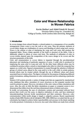
Figure 5. A Threading Not on the Network and Three Peg Plans. . . . . . . . . . . . . . . . . . . . . . . . . . . . . . . . . . . . . . .* Small squares define the network. Filled squares show the threading.B. DrawdownsFigure 6 illustrates what can be achieved when the rules of network drafting are followed. Apattern line placed on the network leads to a threading draft. Then, when “cut and paste”treatment of three different types of peg plans is carried out, a final peg plan containingaspects of the three different weave structures results. This diagram, from page 10 of AliceSchlein’s book “Network Drafting: An Introduction”, proved to be the Rosetta Stone for me,unlocking the mysteries of network drafting.
Figure 6.An Example of a Design Based on Network Drafting Principles
C. Dissecting the ThreadingThe first 32 threads in the threading draft look like this. They have been separated into twogroups. The top diagram shows the threading for shafts 5-8 and the lower diagram thethreading for shafts 1-4. The vertical bars mark the neighboring threads 1-7 that belong toblock A (threads on shafts 1-4) and the neighboring threads 18-27 that belong to block B(threads on shafts 5-8).Figure 7. The Threading Diagram DissectedBlock BShafts87654Shafts81216202428324321Block AThreads 8-17 and 29-32 don’t belong to a specific block and I like to think of them astransition threads.D. Dissecting the Peg Plan.The same idea can be applied to the peg plan. In order to see this more easily, the peg planis divided, one for shafts 1-4 and the other for shafts 5-8. Now the horizontal bars showregions where the peg plan identifies a specific weave structure (plain weave, 1-3 twill, or 3-1twill). Those regions have been pulled out to the right or left so they are easy to identify.The peg plans numbered 6-19 and 31-36 on shafts 1-4 and the peg plans numbered 7-18and 30-36 on shafts 5-8 can be considered to be transition peg plans.
Figure 8. The Peg Plan DissectedShafts5 6 7 81 2 3 41 2 3 44488Plain Weave5 67 81/3 Twill121216162020242428285 67 81 2 3 4Plain Weave3/1 Twill32363236Perhaps there is an easier way to see the total picture. So let’s go back to the full design.But now only those threading regions that belong to either block A or B are shown. Inaddition only those peg plans that belong exclusively to shafts 1-4 or shafts 5-8 are indicated.When the drawdown is made, there are isolated islands where the three different weavestructures appear. Here is that drawdown. Remember that this works because all of thethreads fall on the network.It is worthwhile to compare figures 6 and 9.
Figure 9. Partial Drawdown Showing Regions of Pure Weave StructuresBut how about the white areas in this diagram? I began to see them as transition regionsbecause the threading did not fall within either block A or block B, or because the peggingplans did not belong either to shafts 1-4 or shafts 5-8, or because of both of these. I finallyhad the answer I was searching for, namely, what happens in network drafting. These ideascan be presented schematically.Figure 10. Schematic Diagram to Show Islands of a Single Weave StructureAnd Regions of Transition Weave Structures
Shafts 1-4PlainWeaveSingleTransitioninPeg Plan3/1Left TwillSingleTransitioninPeg PlanPlainWeaveShafts g Plan ioninPeg Plan &ThreadingSingleTransitioninThreading1/3Right TwillSingleTransitioninPeg PlanPlainWeaveSingleTransitioninPeg Plan1/3Right TwillShafts g Plan ioninPeg Plan gleTransitioninPeg Plan3/1Left TwillSingleTransitioninPeg PlanPlainWeave
II. Network Drafting for Double Weave.The ideas expressed in figure 10 should apply just as well in double weave as in singleweave. One schematic diagram looks like this.Figure 11. Schematic Diagram for Network Drafting for Double WeaveShafts 1-4DoubleWeave ISingleTransitioninPeg PlanDoubleWeave IISingleTransitioninPeg PlanShafts g Plan ioninPeg PlanDoubleWeave IDoubleTransitioninPeg Plan &ThreadingDoubleWeave IDoubleWeave IISingleTransitioninThreadingSingleTransitioninPeg PlanDoubleWeave IIShafts g Plan ioninPeg Plan &ThreadingSingleTransitioninThreadingDoubleWeave ISingleTransitioninPeg PlanDoubleWeave IISingleTransitioninPeg PlanDoubleWeave I
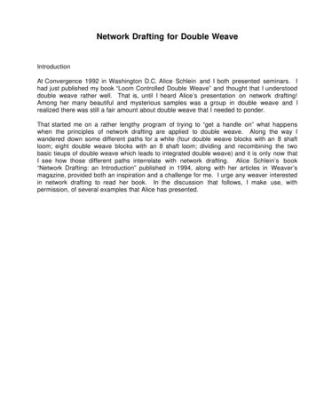
The two basic peg plans for double weave that I have called Double Weave I and DoubleWeave II have the forms shown here. Both produce two cloth layers, traditional doubleweave.WARP COLORD L D LD L112D L41 2322 3 4133 44When the weft color order is also DLDL, the first of these peg plans produces a dark top layerand a light bottom layer while the second gives the opposite effect, light on top and dark onthe bottom.Alice Schlein uses a different setof rules from those I use.Her threading is right to left and her warp color order is LDLDMy threading is left to right and I use warp color order DLDL.Her weft color order is LDLD while mine is DLDL.Because of this the two basic peg plans become reversed.In this book when I use one of Alice Schlein's examples, I willuse her rules. All other examples are presented with my rules.Here is an example that Alice Schlein presents in her article on page 54, Weaver’s MagazineIssue 33, Fall 1996. The drawdown is slightly modified to show the dark and light threads inthe top layer of double weave.
Figure 12. Waves # 1Well so far, so good. There definitely seem to be regions that are all light or all dark withtransition regions along the edges of those regions. My hypothesis is holding together. Let’scheck things out in a bit more detail by examining the peg plans for Waves # 1.A. Peg Plans for Waves # 1, Testing the Hypothesis!I expected to find Peg Plan I and Peg Plan II somewhere in each column to provide for theareas that are light or dark in the top layer, along with a number of peg plans that create thetransition regions. Here are the four columns of pegging presented separately so they areeasier to examine. In addition the pegging is grouped in sets of four.
Figure 13. Analysis of Peg Plan for Waves # 1Shafts13-169-125-81-4LLtrLtrtrLtrLLCertain things look pretty good. There are regions where the light layer of traditional doubleweave appears and there are regions where the transitional motifs of integrated doubleweave will show up.BUT!Where are the sections with the dark layer of traditional double weave? Both the picture inWeaver’s magazine and the computer printout indicate that there should be a meanderingline of black. So someplace in each column there should be peg plan II to indicate where thedark layer of traditional double weave will be in the overall weaving. Careful checking failedto find peg plan II in the overall peg plan. There is of course the possibility that I hadoverlooked something. I pondered the situation for several days and suddenly the answerpopped into my mind one night as I was going to sleep. It seems that I had returned to LotusLand where the peg plans are always in groups of four!Sure enough! I looked down each column to see if the four lines of peg plan II showed up butnot necessarily in a well ordered group of four. Lo and behold, there they were hidden in the
transition sections. The next diagram shows the new analysis.Figure 14. New Analysis of Peg Plan for Waves # Voila and eureka!The dark peg plans show up in three different ways. This was an important message for me.Peg plans are not limited just to groups of four nor do they have to appear always in a certainorder.B. What Lies Ahead?Before embarking on a more general discussion of network drafting for double weave in thenext chapter, I want to give one example of how a network drafting design may be extended.The transition regions in the peg plans in many examples of network drafting are relativelyshort so why not extend them. I repeat the drawdown for Waves # 1 in figure 15 and thenshow how it can be modified by lengthening the transition pegging sections.
Figure 15. Original Drawdown for Waves # 1Figure 16. Drawdown for Waves # 1 with Additional Transition Pegging Sections
Chapter II. Some Nuts and Bolts of Network DraftingI. Some Threadings on the 4-End InitialThe 4-end initial on 8 shafts will be used in this chapter. The asymmetrical threadings infigure 1A can be used for either single or double layer weaves. The threading in I B can beused for a single layer weave but not for double weave while the threading in I C can be usedfor double weave but not for single weave.Figure 1. 4-End Initial on 8 ShaftsA. Two Asymmetrical ThreadingsB. A Symmetrical ThreadingC. Another Symmetrical ThreadingThe network in figure I B can be used for any single layer weave that can be woven on the 4end initial because threads always alternate on odd and even number shafts. In the mostcommon form of double weave, threads on odd numbered shafts are in one cloth layer andthe threads on even number shafts will be in the other cloth layer. This means that at theturning point in figure I B two threads on shaft 8 will always weave together in one of the clothlayers of double weave. A way to avoid that problem is to use the network shown in figure IC.
Whenever a turning point is introduced in the threading for doubleweave in order to achieve horizontal symmetry, two extra threadsare added to the threading draft to avoid a weaving error.However for the computer prints shown in this book, only one extrathread is shown at the turning point. This is to avoid a computerartifact. If you use any of the threadings, be sure to add twoat every turning point in the threading draft.A great variety of threadings can be derived. I find it helpful to develop a threading on thenetwork by looking at groups of 4 threads. For example, figure 2 shows how the threading offigure I C can be expanded to bring out the 4 thread groupings. The first and last are oftenlabeled as block A and block B for traditional 8 shaft double weave. The middle three can beconsidered transition blocks (they become important in weaving 4 or 8 blocks of doubleweave with an 8-shaft loom).Figure 2. 4 Thread GroupingsThe real advantage in looking at threading in this fashion is that new or expanded threadingsare so easy to derive. These four thread groups can be repeated or deleted or rearranged atwill because the threading will always fall on the network. Examples of this will be presentedin Chapters III and IV.II. Threading, Tieup, Peg Plan and TreadlingA. For Non-Symmetrical DesignsAll floor loom weavers soon become familiar with the format for making a drawdown: from thethreading to the tieup to the treadling order to the drawdown. Figure 4 gives an example(without the actual drawdown!) which could be used with a treadle loom, a table loom, or adobby loom.
Figure 3. Scheme Leading to the DrawdownShaft #87654321ThreadingTieuporoPeg Plan Rotated 9Treadling OrderDrawdownA dobby loom can be set up in a slightly different way which is shown next.sometimes referred to as “single ties to multiple treadles”.This isFigure 4. An Alternate Scheme Leading to the DrawdownThreadingTreadling Order1 2 3 45 6 7 8DrawdownShaft #Peg PlanB. For Symmetrical DesignsIt is quite straightforward to make designs symmetical in the horizontal direction (throughchanges in the threading) or in the vertical direction (through changes in the treadling orderor in the peg plan). Figure 4 repeats the information in figure 3 to show how symmetry can beachieved. For double weave note that it is necessary to have two extra threads so that errorsdo not occur in either the top or the bottom cloth layers. Similarly two extra treadlings or pegplans are required for the same reason. The extra threads and treadlings or peg plans havebeen separated to let you see more easily what happens before each of these is reversed toachieve symmetry.
Figure 5. Symmetrical Schemes leading to the DrawdownsShaft #87654321ThreadingDrawdownTieuporoPeg Plan Rotated 90Treadling OrderThreadingTreadling Order1 2 3 45 6 7 8Shaft #DrawdownPeg PlanRULE. Remember two extra warp threads are needed at the turning point for horizontalsymmetry and two extra treadlings or peg plans are needed at the turning point for verticalsymmetry.So having said that I want to alert you to the fact that all of the computer printouts wheresymmetrical designs are given do not follow that rule. Sorry. The reason is that the weaveprograms I have been using with my MacIntosh computer do not have the capability to showthe two sides of a double woven fabric. Figure 6 shows examples of the threading, treadlingand peg plan format used for the computer printouts. REMEMBER to carry out the weavingin the manner of figure 5, not figure 6.
Figure 6. The Formats for the Computer PrintoutsTreadling OrderPeg Plan1 2 34 5 67 8ThreadingFurther explanation is presented in Appendix C. But as my computer son says, this is “ geekstuff”.III. Transitions between Peg PlansA basic element in network drafting is the transition that occurs from one weave structure toanother weave structure. The pattern line provides a very efficient way to derive thethreading and the peg plan for this transition. I would like to present another method thatlooks at the peg plan in a more general manner. In double weave there are six different pegplans giving different combinations of the four warp threads in the two layers. The discussionhere is limited to Peg Plan I (dark top layer, light bottom layer) and Peg Plan II (light top layer,dark bottom layer). The transition between the two peg plans is given in figure 7. Thenumbers used in the peg plans are for shafts 1-4 but of course the diagrams are applicable toother shafts.Figure 7. Transition between Peg Plan I and Peg Plan II1 211 213232343 444There are several things in these two diagrams that are identical. First, some numbersalways appear in the same place which means that there is always a peg in that square.Second, four empty spaces always appear in the same place which means there is never apeg in that position. In figure 8, a zero, 0, indicates a square where a peg never appears.Figure 8. Common Features of the Two Basic Peg Plans01020304That leaves eight squares in Figure 8 where a peg may or may not go. “To peg or not to peg”
are the choices. Two choices for each empty space lead to a total of2 x 2 x 2 x 2 x 2 x 2 x 2 x 2 256different peg plans for double weave. These peg plans are given in Appendix A-1 with theirdrawdowns and A-2 with their drawups. Let me show the drawdowns for two of the 256 pegplans, the first where no additional pegs are added to figure 8 and the second where eightadditional pegs have been added. The procedure I use for drawdowns is presented in figure9. The peg plan comes first and next a diagram where dots replace the numbers. The thirddiagram is a warp drawdown for the dark warp threads (a jack loom with rising shed isassumed). In the final square, dark weft threads complete the drawdown. (An empty squareindicates a light weft thread in the top layer and a square with a black dot stands for a lightwarp thread also in the top layer.)Figure 9. From Peg Plan to Drawdown in Four StepsPeg PlanZero Additional Pegs1234Drawdown.Dark WarpDrawdown. .DrawdownDLDLD L D LD LD LThe finished weaving looks like the first of the next two diagrams when the grid lines and dotsare erased. The second diagram shows the weave structure with the DLDL color order forboth the warp and the weft.Peg Plan8 Additional Pegs5 685 6 76 7 87 85Drawdown. . . .Dark WarpDrawdown. . . .D L D LThe appearance of the weaving and the weave structure are shown next. . . . .DrawdownDLDLD L D L
For two of the 256 peg plans, peg plans I and II, there will be the two cloth layers of traditionaldouble weave. Half of the warp and weft threads are in one cloth layer and the other half arein the second cloth layer. Because of this the sett that is recommended for traditional doubleweave is twice the sett for single layer plain weave.For the remaining 254 peg plans, there will be a single cloth layer in integrated doubleweave. All warp and weft threads are in the same cloth layer and the sett should revert to theone proper for single layer plain weave, that is half the sett appropriate for two layer doubleweave.So what should be the sett for a weaving that has some areas in traditional double weaveand other areas in integrated double weave? If the sett is proper for the two layer sections,then twice as many threads are crowded into the integrated double weave section. On theother hand if the sett is proper for the single layer areas, then the two-layer region willprobably be much too loose. Well there is no one answer except to try different setts andchoose the one you like. I find that a sett that is about 10 - 20 % more open than the sett usedfor traditional double weave seems about right.IV. Another Look at the 254 Peg PlansThe drawdowns in Appendix A-1 are all one unit on a side. More revealing are drawdownsof two units on a side and these are given in Appendix B-1. Notice that there are far fewerthan 254 distinct designs and they have been grouped in Appendix B-1 to emphasize this.Some are shifted up or down by a few threads. Others are the positive-negative images ofeach other. In figure 10 the drawdowns and weave structures for the tieups numbered 4-36and 4-63 are shown. The drawdowns come from Appendix A-1 and the 4 unit drawing fromAppendix B-1.Figure 10. The Drawdowns and Weave Structures for Two of the 254 Peg Plans4-364-361142 32 344-634-6311 22 3344
The designs in single unit size seem to be quite different. However the four unit drawdownsbegin to reveal their similarity. In the example used here, the designs are the positivenegative versions of each other. Also the design of 4-63 has been shifted by one thread inboth the vertical and horizontal directions from the design in 4-36.The weave structurediagrams in figure 9 and 10 show that the warp and weft threads interlock so that none of thethreads can slide under other threads, two more examples of integrated double weave,single layer weaves that show all the warp and weft threads. That this is not always true isexplained in Appendix D where the problem of drawdown for double weave is developedmore extensively.
Chapter III. Some Networked Double Weave Designs, Using TieupsIt is time to get down to business!The next chapters discuss some of the designs that can be woven in double weaveusing network drafting principles and how to achieve or alter them. The approach inthis chapter is based on the use of tieups and works with a treadle floor loom, a tableloom with levers to lift each shaft independently, or a dobby loom.I think of two of the basic designs in double weave as “windows” and “checkerboards”and want to discuss them separately. Eight shafts are required to weave thesedesigns.I. The Windows DesignFigure 1 shows the threading, tieup, and treadling needed to weave an 8 shaft doubleweave windows design. A drawing shows what the drawdown looks like. Thewindows can be square or rectilinear, wide or tall. Eight treadles or eight dobby barsare required in the weaving. This is made explicit in figure 1 by expanding each partof the diagram so that it is easy to see what happens.Figure 1. The Windows Design in Double WeaveTieupShaft #ThreadingBackground87654321Window DesignTreadlingWindow
The transition zones when the design is networked are presented in figure 2. Thevertical arrows correspond to transition in the threading. The horizontal arrowscorrespond to transition in the tieup or the peg plan. Single diagonal lines showwhere the woven area is a result of the transition in either the threading or the tieup.The crosshatch lines show where the woven area is a result of the transitions in boththe threading and the tieup. These designs tend to have the rectilinear appearance oftraditional double weave and not the curved shapes that are often seen in networkingdrafting.Figure 2. Transition Regions in the Window DesignB. Computer Printouts for some Window DesignsA variety of threadings have been used in the designs that are shown below and alsoin the next section where the checkerboard design is used. The first printout is fortraditional double weave and is an expansion of the threading in figure 1. Notice thatthere is symmetry in the horizontal and vertical directions.
Figure 3. Some 8 Shaft Window Designs for Networked Double WeaveTraditional Double WeaveTransition 1 B in Threading and TreadlingTransition 1 D in Threading and TreadlingTransition 1 A in Threading and TreadlingTransition 1 C in Threading and TreadlingTransition 1 E in Threading and Treadling
II. The Checkerboard DesignFigures 8 and 9 show the threading, tieup and treadling needed to weave an 8 shaftcheckerboard design and should be compared with figures 1 and 2 of section I wherethe window design for double weave was discussed.Figure 4. The Checkerboard Design in Double WeaveShaft #ThreadingTieup87654321Checkerboard DesignTreadlingFigure 5. The Checkerboard Design Networked
Here are some computer printouts for the 8 shaft double weave checkerboard design.The central checkerboard square has been enlarged in the last printout to improve thedesign. Even so, it seems to me that the overall impact for I C is not very pleasing.Figure 5 Some 8 Shaft Checkerboard Designs in Network Double WeaveTraditional Checkerboard designTransition I ATransition I CI decided to take one example, II B, to see if I could create a design I did like. Figure 6shows the modifications I made. The first major change introduced a backgroundaround the checkerboard creating a window design where the window was in the formof a checkerboard. I needed to use 12 shafts to achieve this. The design was stillconfusing to me so I began to delete sections in the threading and treadling order andreplace them with more of the background. The easiest way to do this was to shiftthreads from shafts 5-8 to shafts 9-12, always staying on the network. Notice also thatthe original checkerboard squares are larger and some are rectangular in shape. Ifelt that these changes produced a much more satisfactory double weave design.
Figure 6.The Development of a Design in Networked Double WeaveThe Development of a Checkerboard Design in Networked Double WeaveTransition II B in Threading and TreadlingOutline Added, 12 Shafts. Threading Extended3-27142 32 3Variation I4Variation II
III. A Different Treatment for the Windows Design.The window part of the designs presented in sections I and II of this chapter has beenin traditional double weave with peg plan II producing the light top layer. However anyof the other 254 peg plans could have been used for the windows. Figure 7 showshow the tieup can be altered substituting another peg plan for peg plan II.Figure 7. Changing the Tieups for the Window DesignTieupTieupWindow BackgroundWindow BackgroundHere are some examples of what happens when this substitution is made. For eachdrawdown, the peg plan from Appendix A-1, with its identifying number and the 2 x 2drawdown from Appendix B-1 are given. Remember that the window is now inintegrated double weave, a single cloth layer. All of the designs are symmetrical.Figure 8. Substitution of other Peg Plans in the Window Design0-112348-141 21 2 32 3 413 4
4-291 22 33 4144-2411223 43 4
Chapter IV. Some Networked Double Weave Designs, Using Peg PlansA. Some 8 Shaft Window Designs using Peg PlansWith a dobby loom, peg plans can be used rather than tieups (this method issometimes called “single ties controlling multiple treadles”). Compare this diagramwith figure 1 in chapter III.Figure I. The Windows Design in Double Weave using Peg PlansShaft #ThreadingTreadling Order87654321Window DesignPeg PlanFigure 2 presents a series of diagrams beginning with a traditional double weavewindow design, adding transitions in the threading, the peg plan, and then both thethreading and the peg plan. Diagram E extends the transition in the threading to showhow changes can easily be made. The figures have a more curved appearance withthis system than was true for tieups.
Figure 2. Some 8 shaft Window DesignsA. Traditional Double WeaveC. Transition in Peg Plan OnlyB. Transition in Threading OnlyD. Transition in Threading and Peg PlanE. Extended Transition in the ThreadingSame Transition in the Peg PlanAll of the examples are symmetrical in the horizontal direction. It is as easy to makethe designs symmetrical in the vertical direction when using peg plans as was true inthe system that used tieups. Here is how to do it. Choose the point where you want
the design to become vertically symmetrical. Now simply reverse the entire peg planback to the beginning. This is shown in figure 3 for the two peg plans at this reflectionpoint.Figure 3. Reversal of the Peg Plan to Achieve Vertical SymmetryPeg PlanShaft Number8 76 5Color of Weft Shot123456784 3 2 1Line of SymmetryThe peg bars for the fourth and the fifth weft shots are the same, a weaving error in thetop layer. Moreover the third and sixth weft shots are the same, a weaving error in thebottom layer.In Chapter II section II, the methods to achieve horizontal and vertical symmetry werediscussed. To achieve horizontal symmetry, two additional warp threads must beadded before reversing the threading and to achieve vertical symmetry, two additionalpeg bars must
structure is called its "initial". The initial in figure 1 applies for a number of weave structures including plain weave, basket weave, many 4 shaft twill weaves, and double weave. Figure 1. The 4-End Initial. Shafts 4 . 3 2 1 An initial is used to build up a network which may be right or left handed and can also be a combination of .