Transcription
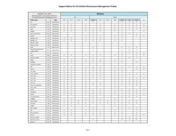
Technical DataXM Monitoring Modules SpecificationsCatalog Numbers 1440 SeriesThe XM series of intelligent I/O modules process, in real-time, the critical parameters that are used to assess the currenthealth and predict the future health of industrial machinery. This real-time processing provides machinery protection andreduces downtime. Use the XM modules in a standalone system, or integrate them with existing automation and controlsystems.TypeModuleCat. No.PageMeasurement modulesXM DYN Dynamic Measurement Module1440-DYN02-01RJ2XM-124 Standard Dynamic Measurement Module1440-SDM02-01RA6XM-220 Dual Speed Module1440-SPD02-01RB12XM-441 Expansion Relay Module1440-REX00-04RD17XM-442 Voted EODS Relay Module1440-REX03-04RG20Terminal Bases1440-TB-A, 1440-TB-B, 1440-TB-D,1440-TB-G, 1440-TBS-J23Serial Configuration UtilityN/A24Fuse Kit1440-5AFUSEKIT24Serial Communication Cable1440-SCDB9FXM225ControlNet Adapter1440-ACNR25Relay modulesAccessories
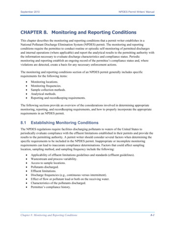
XM Monitoring Modules SpecificationsXM DYN Dynamic Measurement ModuleThe XM dynamic measurement module (catalog number 1440-DYN02-01RJ) is a two-channel, general-purpose monitorthat supports measurements of dynamic inputs such as vibration, pressure, and strain. You can use the module to monitorshaft, casing, and pedestal vibration in equipment that rotates. The module is designed specifically for integration withControlLogix controllers, which are connected through the 1440-ACNR ControlNet adapter.Table 1 - XM DYN Dynamic Measurement Module Attribute DescriptionsAttributeXM DYN (1440-DYN02-01RJ)InputsTwo dynamic channel inputs Eddy current transducer signals Accelerometer signals Voltage signals from any dynamic measurement sensor such as velocity or pressure transducerTransducer power Voltage ranges -20 0V DC -10 10V DC 0 20V DCInput impedance 100 k SensitivityUp to 15% from nomConstant voltage 24V DC, -24V DC, 60 mAConstant current 4.5 mA 30%/-20% from 24V DC (IEPE)Bias current: monitors self-powered coil-based 0Tachometer InputOne tachometer input 25V (50V max peak-to-peak)Input impedance 120 k Range1 1.2 M rpm/0.0167 20 kHzPulses per revolution0 (tach off) 50,000Rate of change of speed, max500 Hz/sOutputsBuffered outputs2 One active buffer per dynamic channel One resistive buffer for tachometerRockwell Automation Publication 1440-TD001G-EN-P - June 2018
XM Monitoring Modules SpecificationsTable 1 - XM DYN Dynamic Measurement Module Attribute Descriptions (continued)AttributeXM DYN (1440-DYN02-01RJ)IndicatorsStatus indicators ModuleNetworkChannel 0Channel 1TachometerSetpoint multiplierVirtual relay Autobaud 125 Kbps, 250 Kbps, or 500 KbpsMax distance: 10 m (32.81 ft)Node number that is mechanically set to simplify installation and commissioningCustomizable poll assembly optimizes space utilization within scannerLogix Controller integration over the ControlNet network Via 1440-ACNR AdapterCommunicationXM busSignal ConditioningSampling mode Selectable per channel Asynchronous– FMAX: 1 Hz 20 kHz Synchronous– FMAX: 10 Orders x Speed (Hz) 5000– Order range: 4 200– Min FMAX: 10 Hz– Max FMAX: 5000 HzResolution A/D conversion: 24 bits Dynamic range: 80 dBfs (0.01% fs), 90 dBfs, typicalFFT lines100, 200, 400, 800IntegrationNone, single, or doubleHigh pass analog filters -3 dB corners: 0.2, 1, 5, 10, 40 HzRoll off: -30 dB/octave for the 0.2 Hz filter, otherwise 24 dB/octave Spike Energy gSE HPF: 200, 500, 1000, 2000, 5000 HzRoll off: -12 dB/octaveLow pass filter Applied to integrated acceleration measurements -6 dB corner: 2 kHzRoll off: -12 dB/octaveUnitsg, ips, mm/s, mils, μm, PSI, mbar, voltMeasurementsTypes FFT and time waveform Asynchronous or synchronousReal timeOverall RMS Peak (true or calculated) Peak-to-peak (true or calculated) Optional low pass filter– -3 dB corner: 200 Hz 20 kHz– Roll off: -24 dB/octave Gap (or transducer bias voltage) Speed SMAX magnitude SMAX phaseRockwell Automation Publication 1440-TD001G-EN-P - June 20183
XM Monitoring Modules SpecificationsTable 1 - XM DYN Dynamic Measurement Module Attribute Descriptions (continued)AttributeXM DYN (1440-DYN02-01RJ)FFT derived FFT bands– Four bands per channel– Defined in frequency or order domain– Overall or max peak in band Orders– Magnitude: 1x, 2x, 3x– Phase: 1x, 2x Not 1x Sum harmonicsAlarmsNumber Six alert and danger pairs Alarm on any measured valueOperators HysteresisUser-definedStartup inhibit/setpoint multiplication Period 0 1092 min Inhibit/multiplication function:Multiply by N (0 10, 0 Disarm)Speed inhibitSpeed range can be specified for each alarm. When applied, the alarm is disabled if the speed is outside the defined rangeGreater thanLess thanInside rangeOutside rangeConfigurationAutomatic module configurationAutomatically configured from a configuration that is stored in module memory at power-up, or from a configuration that is heldin a Logix5000 controller.RelaysOne virtual relay Logic is provided to drive one virtual relay. Relay status indicatorRelay function Normally energized (fail-safe) or normally de-energized (non-failsafe)Latching or non-latchingTime delay: 0 25.5 s in100 ms incrementsSingle or paired AND or OR logic applied to any alarmReset by digital command from configuration software, via a command from the XM bus, or from output tag when integratedvia ControlNet adapterAlarm status to activate on NormalAlertDangerGap/bias out of rangeModule faultTachometer faultDisarmPower4TypeRequires Class 2 power supplyModule24V DCConsumption 250 mA, max 210 mA, typicalHeat production 4.56 W, max 3.60 W, typicalNorth American Temp CodeT4AIEC Temp CodeT4Rockwell Automation Publication 1440-TD001G-EN-P - June 2018
XM Monitoring Modules SpecificationsTable 1 - XM DYN Dynamic Measurement Module Attribute Descriptions (continued)AttributeXM DYN (1440-DYN02-01RJ)EnvironmentalTemperature, operating-20 70 C (-4 158 F)Temperature, storage-40 85 C (-40 185 F)Relative humidity5 95% noncondensingPhysicalTerminal base1440-TBS-JDimensions (H x W x D), approx97 x 94 x 94 mm (3.8 x 3.7 x 3.7 in.)Weight, approx0.172 kg (0.38 lb)Certifications(1)cULusUL Listed for US and Canada. See File E234338UL Listed for Class I, Division 2 Group A,B,C,D Hazardous Locations, which are certified for U.S. and Canada. See UL File E194810CEEuropean Union 2004/108/EC EMC Directive, compliant with: EN 61326-1; Meas./Control/Lab., Industrial Requirements EN 61000-6-2; Industrial Immunity EN 61000-6-4; Industrial Emissions EN 61131-2; Programmable Controllers (Clause 8, Zone A & B)C-TickAustralian Radiocommunications Act, compliant with: AS/NZS CISPR 11; Industrial EmissionsExEuropean Union 94/9/EC ATEX Directive, compliant with: EN 60079-15; Potentially Explosive Atmospheres, Protection "n" EN 60079-11; Explosive Atmospheres, Protection "i" EN 60079-0; General Requirements Ex nA IIC T4 X GcKCCKorean Registration of Broadcasting and Communications Equipment, compliant with: Article 58-2 of Radio Waves Act, Clause 3(1) When product or packaging is marked. See the Product Certification link at http://www.rockwellautomation.com for Declarations of Conformity, Certificates, and other certification details.Rockwell Automation Publication 1440-TD001G-EN-P - June 20185
XM Monitoring Modules SpecificationsXM-124 Standard Dynamic Measurement ModuleThe XM-124 module (catalog number 1440-SDM02-01RA) is a two-channel, general-purpose monitor that supportsdynamic measurements such as vibration, pressure, strain, and spike energy (gSE). The module also supports static (DC)thrust and eccentricity measurements.The XM-124 consolidates and improves on most of the functionality that is provided by the earlier XM-120, XM-120E,XM-121, XM-122 and XM-123 modules. It also provides the same basic, single-channel, thrust measurement as the XM320 module. The XM-124 is suitable for monitoring almost any rotating machine, including steam turbines, aeroderivativeand industrial gas turbines, hydro turbines, motors, pumps, fans, compressors, and gearboxes.Table 2 - XM-124 Standard Dynamic Measurement Module Attribute DescriptionsAttributeXM-124 (1440-SDM02-01RA)InputsTwo dynamic channel inputs Eddy current transducer signals Accelerometer signals Voltage signals from any dynamic measurement device, such as a velocity or pressure transducerTransducer power Voltage range -20 0V DC -10 10V DC 0 20V DCInput impedance 100 k SensitivityUp to 15% from nomConstant voltage: 24V DC, -24V DC, 40 mAConstant current 4.5 mA 30% / -20% from 24V DC (IEPE)None (voltage input)Tachometer can be powered, constant voltage, or configured as voltage r Input6One tachometer input 25V (50V max peak-to-peak) 1 50,000 events/revolutionInput impedance 120 k Range 1 1,200,000 rpm 0.0167 20,000 HzPulses per revolution0 (tach off) 50,000Rate of change of speed, max500 Hz/sRockwell Automation Publication 1440-TD001G-EN-P - June 2018
XM Monitoring Modules SpecificationsTable 2 - XM-124 Standard Dynamic Measurement Module Attribute Descriptions (continued)AttributeXM-124 (1440-SDM02-01RA)Outputs4 20 mA Each output is independently programmed to represent any measured parameter, from either channel Two isolated outputs 300 max loadBuffered outputs One active buffer per dynamic channel One resistive buffer for tachometerIndicatorsStatus indicators ModuleNetworkChannel 1Channel 2TachometerSetpoint multiplierVirtual relayDeviceNet network Standard DeviceNet protocol for all functions (not power—module power is provided independently)Available EDS file supports most DeviceNet compliant systemsCommunication rate that is set automatically by bus master to 125 Kbps, 250 Kbps, or 500 KbpsConfigurable I/O Poll Response message helps optimize space utilization within scanner input tables:– Selectable poll response assembly– Selectable poll response size (bytes)Serial RS-232 via mini-connector or terminal base unit Communication rate that is fixed at 19.2 Kbps Local configuration via the Serial Configuration UtilityCommunicationSignal ConditioningSampling mode Selectable per channel Dynamic Measurements– AsynchronousFMAX: 1 Hz 20 kHz– Synchronous Order range: 4 200–Min FMAX: 10 Hz–Max FMAX: 5000 Hz, Measured: Orders x Speed (Hz) Spike Energy Static Measurements– EccentricityPeak-to-Peak Eccentricity ThrustNormal mode (single channel measurement)Resolution A/D conversion: 24 bits Dynamic range: 80 dBfs (0.01% fs), 90 dBfs, typicalFFT lines100, 200, 400, 800, 1600IntegrationNone, single, or doubleHigh pass analog filters -3 dB corners: 0.2, 1, 5, 10, 40 HzRoll off: -30 dB/octave for the 0.2 Hz filter, otherwise 24 dB/octaveLow pass analog filter Applied to integrated acceleration measurements -3 dB corner: 5 kHzRoll off: -18 dB/octaveRockwell Automation Publication 1440-TD001G-EN-P - June 20187
XM Monitoring Modules SpecificationsTable 2 - XM-124 Standard Dynamic Measurement Module Attribute Descriptions (continued)AttributeXM-124 (1440-SDM02-01RA)Low pass digital filterIndependently configured per channel Optional Overall LP Filter 100 20000 Hz Spike Energy Spectra FMAX: 10 5000 Hz Roll Off: -24 dB/octaveTracking digital filterIndependently configured per channel Tracked speed multiple: 0.1 20.0 times the measured (tachometer) rpm Constant Q: 1 200 Constant bandwidth: 0.1 25 Hz Roll off: -36 dB/octave, typicalBand pass digital filterIndependently configured per channel Frequency, min 25 1000 Hz Frequency, max 100 5500 Hz Roll off: -60 dB/octaveUnitsg, ips, mm/s, mils, μm, PSI, mbar, voltData(1)Complex data Spectra (synchronous or asynchronous)Waveform (synchronous or asynchronous)Simultaneous waveforms (synchronous)gSE SpectraAccuracy, min 1% of full scale range for the channel 1% of alarm setpoint for speedMeasurements(2)Types FFT and time waveform Asynchronous or synchronousReal time FFT derived8OverallRMSPeak (true or calculated)Peak-to-peak (true or calculated)gSE(5)Optional low pass filter– -3 dB corner: 200 Hz 20 kHz– Roll off: -24 dB/octaveGap (or transducer bias voltage)SpeedSMAX magnitudeSMAX phaseBand pass filter valueTracking filter magnitudeTracking filter phaseThrust positionEccentricity FFT bands– Four bands per channel– Defined in frequency or order domain– Overall or max peak in band Orders– Magnitude: 1x, 2x, 3x– Phase: 1x, 2x Not 1x Sum harmonicsRockwell Automation Publication 1440-TD001G-EN-P - June 2018
XM Monitoring Modules SpecificationsTable 2 - XM-124 Standard Dynamic Measurement Module Attribute Descriptions (continued)AttributeXM-124 (1440-SDM02-01RA)Data BuffersDelta time buffer Number of records: 2048 Delta time interval: 1 3600 s Trigger mode: Relay is activated or trigger event (such as DeviceNet command from a controller or host)Delta rpm buffer Number of records: 512 Delta speed interval: 1 3600 rpm Trigger mode: Startup collects data in increasing rpm direction only; coast-down collects data in bothincreasing and decreasing directions The data that is collected in the buffer is user configurable and can contain up to 16 of the measurementsSpectra or waveformSaved upon same trigger as delta time bufferAlarmsNumberSixteen alarm and danger pairsAlarm parametersAny measured parameterOperators HysteresisUser configurable in softwareStartup inhibit/setpoint multiplication Period: 0 1092 min, adjustable in 0.1 min increments Inhibit/multiplication function:Multiply by N (0 10, 0 Disarm)Speed inhibitA speed range can be specified for each alarm. When applied, the alarm is disabled when speed is outside ofthe defined range.Greater thanLess thanInside rangeOutside rangeRelaysNumber Single on-board relay, Single Pole Single Throw (SPST), one Form A Four additional DPDT relays when interconnected to an XM-441 expansion relay module, or Four virtual relays whose status can be used by remote control systems or the XM-440 master relay module,also four DPDT relaysRating (resistive) Expected life (min operations) Mechanical: 2x10⁷ Electrical @ 20 cpm– 1.5 A, 24V DC: 10 5Failsafe Normally energized (fail-safe) or Normally de-energized (non-fail-safe)Latching Latching Non-latchingTime delay0 25.5 s, adjustable in 100 ms incrementsLogicSingle or paired AND or OR logic applied to any alarmReset Local reset switch on top of module Remote reset switch that is wired to terminal base Digital reset command via serial or DeviceNet interfaceCapacity, nominal: 1.5 A @ 24V DCCapacity, min 100 μA @ 100 mV DCPower, max 41.4 WVoltage, max 27.6V DCCurrent, max 1.5 ARockwell Automation Publication 1440-TD001G-EN-P - June 20189
XM Monitoring Modules SpecificationsTable 2 - XM-124 Standard Dynamic Measurement Module Attribute Descriptions (continued)AttributeXM-124 (1440-SDM02-01RA)Activation on Alarm status– Normal– Alert– Danger– Disarm– Transducer fault– Module fault– Tacho faultPeak speed captureThe XM-124 retains the value of the highest speed that is observed since module power was cycled or the peakspeed value was manually resetConfigurationNonvolatile configuration A copy of the module configuration is retained in nonvolatile memory from which the configuration isloaded upon powerup The configuration that is stored in nonvolatile memory can be deleted only by a module-reset commandthat is sent via a serial interface, using the Serial Configuration Utility or via a DeviceNet interface from anycompliant software applicationModulePower supply 24V DC 350 mA Requires Class 2/SELV/PELV power supplyPower dissipation8.7 W, maxIsolation voltage 50V (continuous), basic insulation type between uninsulated live parts and the enclosure with the relaycontacts open and closed Type tested at 707V DC for 60 s between uninsulated live parts and the enclosure with the relay contactsopen and closed Type tested at 707V DC for 60 s between supply and output terminalsWiring category(3) North American temp codeT5IEC temp codeT42 - on signal ports1 - on power and relay ports2 - on DeviceNet ports3 - on serial portsEnvironmentalTemperature, operating-20 65 C (-4 149 F)IEC 60068-2-1 (Test Ad, Operating Cold),IEC 60068-2-2 (Test Bd, Operating Dry Heat),IEC 60068-2-14 (Test Nb, Operating Thermal Shock)Temperature, surrounding air max65 C (149 F)Temperature, storage-40 85 C (-40 185 F)IEC 60068-2-1 (Test Ab, Unpackaged Nonoperating Cold),IEC 60068-2-2 (Test Bb, Unpackaged Nonoperating Dry Heat),IEC 60068-2-14 (Test Na, Unpackaged Nonoperating Thermal Shock)Relative humidityIEC 60068-2-30 (Test Db, Unpackaged Damp Heat)5 95% noncondensingVibrationIEC 60068-2-6 (Test Fc, Operating)5 g @ 10 500 HzShock, operatingIEC 60068-2-27 (Test Ea, Unpackaged Shock)15 gShock, nonoperatingIEC 60068-2-27 (Test Ea, Unpackaged Shock)30 gEmissionsCISPR11 (IEC 61000-6-4)Class A10Rockwell Automation Publication 1440-TD001G-EN-P - June 2018
XM Monitoring Modules SpecificationsTable 2 - XM-124 Standard Dynamic Measurement Module Attribute Descriptions (continued)AttributeXM-124 (1440-SDM02-01RA)ESD immunityIEC 61000-4-2 6 kV contact discharges 8 kV air dischargesRadiated RF immunityIEC 61000-4-3 EFT/B immunityIEC 61000-4-4 3 kV at 5 kHz on power ports 3 kV at 5 kH on signal ports 3 kV at 5 kHz on DeviceNet portsSurge transient immunityIEC 61000-4-5 1 kV line-line (DM) and 2 kV line-earth (CM) on power and relay ports 2 kV line-earth (CM) on shielded signal ports 2 kV line-earth (CM) on DeviceNet portsConducted RF immunityIEC 61000-4-610V rms with 1 kHz sine-wave 80% AM from 150 kHz 80 MHzEnclosure type ratingNone (open-style)10V/m with 1 kHz sine-wave 80% AM from 80 2000 MHz10V/m with 200 Hz 50% pulse 100% AM at 900 MHz10V/m with 200 Hz 50% pulse 100% AM at 1890 MHz3V/m with 1 kHz sine-wave 80% AM from 2000 2700 MHzPhysicalTerminal base1440-TB-A (XM-940) Series CDimensions (H x W x D), approx97 x 94 x 94 mm, (3.8 x 3.7 x 3.7 in.)Weight Module: 0.172 kg (0.38 lb) Terminal base: 0.172 kg (0.38 lb)Certifications(4)c-UL-usUL Listed for Class I, Division 2 Group A,B,C,D Hazardous Locations, certified for U.S. and Canada. See UL FileE194810.CEEuropean Union 2004/108/EC EMC Directive, compliant with: EN 61326-1; Meas./Control/Lab., Industrial Requirements EN 61000-6-2; Industrial Immunity EN 61000-6-4; Industrial Emissions EN 61131-2; Programmable Controllers (Clause 8, Zone A & B)RCMAustralian Radiocommunications Act, compliant with: AS/NZS CISPR 11; Industrial EmissionsExEuropean Union 94/9/EC ATEX Directive, compliant with: EN 60079-15; Potentially Explosive Atmospheres, Protection "n" EN 60079-11; Explosive Atmospheres, Protection "i" EN 60079-0; General Requirements II 3 G Ex nAC [ic] IIC T4 Gc XKCKorean Registration of Broadcasting and Communications Equipment, compliant with: Article 58-2 of Radio Waves Act, Clause 3(1) Complex data is available when the channel is configured for dynamic measurements.(2) Measurement availability is dependent on channel configuration.(3) Use this Conductor Category information for planning the conductor routing. See Industrial Automation Wiring and Grounding Guidelines, publication 1770-4.1.(4) When product or packaging is marked. See the Product Certification link at http://www.rockwellautomation.com for Declarations of Conformity, Certificates, and other certification details.(5) gSE Measurements can be configured to update continuously, or to alternate with standard acceleration or velocity measurements. The gSE Overall updates in "real-time" only when configured forcontinuous update.Rockwell Automation Publication 1440-TD001G-EN-P - June 201811
XM Monitoring Modules SpecificationsXM-220 Dual Speed ModuleThe XM-220 module (catalog number 1440-SPD02-01RB) measures speed, rotor acceleration, and peak speed and candetect zero speed, locked rotor, and reverse rotation. The module can also serve as a component of an Electronic OverspeedDetection System (EODS).Table 3 - XM-220 Dual Speed ModuleAttributeXM-220 (1440-SPD02-01RB)InputsTwo tachometer inputs 25V (50V max peak-to-peak)Eddy current transducer signalsMagnetic pickupsTTL output devicesInput impedance120 k minSpeed/frequency range 1 1,200,000 rpm 0.0167 20,000 HzSpeed measurement error 1 240 rpm: 0.2 rpm241 12,000 rpm: 2 rpm12,001 20,400 rpm: 5 rpm20,401 120,000 rpm: 20 rpm120,001 360,000 rpm: 50 rpm360,001 1,200,000 rpm: 160 rpm4 20 mA outputs Each output is independently programmed to represent speed or acceleration, from either channelTwo isolated outputs300 max loadOne active buffer per input channelBuffered outputs Output range configurable by wiring:– -24 9V– -5 24V– -5 9V Third buffered output available when the module is configured for single redundant channel mode.Outputs a CMOS (0 5V) level square-wave that corresponds to the active input signalOutputsSensor Fault DetectionEddy current transducerBias voltage is compared with the fault limitsMagnetic pickupsA current source is available for biasing passive magnetic pickups to detect open or short circuitsIndicatorsStatus indicators12 Module - red/greenNetwork - red/greenChannel 1 - yellow/redChannel 2 - yellow/redStartup - yellowRelay - redAUX - reserved for future useRockwell Automation Publication 1440-TD001G-EN-P - June 2018
XM Monitoring Modules SpecificationsTable 3 - XM-220 Dual Speed Module (continued)AttributeXM-220 (1440-SPD02-01RB)CommunicationDeviceNet network Standard DeviceNet protocol for all functions (not power—module power is providedindependently) Available EDS file supports most DeviceNet compliant systems Communication rate that is automatically set by bus master to 125 Kbps, 250 Kbps, or 500 Kbps Configurable I/O Poll Response message helps optimize space utilization within scanner input tables:– Selectable poll response assembly– Selectable poll response size (bytes)Serial RS-232 via mini-connector or terminal base unit Communication rate that is fixed at 19.2 Kbps Local configuration via the Serial Configuration UtilityMeasurementsUnits rpm Direction of rotation Acceleration in rpm/minMeasured parameters Peak speed captureThe module retains the value of the highest speed that is observed since module power was cycled orthe peak speed value was manually resetForwardReverserpmDirection of rotationAcceleration in rpm/minMeasurement ModesDual channelTwo sensors are used independently to perform two separate speed, acceleration and peak speedmeasurementsSingle redundant channelOne sensor is used to perform the speed, acceleration, and peak speed measurements. If the currentsensor fails, the module automatically switches to the second (redundant) sensorReverse rotationTwo sensors are used to monitor both speed and direction. The two sensors must be mounted out ofphase from each other so that the rotational direction can be determined by monitoring which sensorthe shaft keyway passes firstAlarmsNumberEight alarms, which are fixed per channelAlarm parametersAlarm and danger pair that is provided for each of: Speed Acceleration Zero speed Locked rotorOperators HysteresisUser configurable in softwareGreater thanLess thanInside rangeOutside rangeRelaysNumber Single on-board relay, two sets of contacts - DPDT (two Form C) Four additional relays when interconnected to an XM-441 expansion relay module, or Four virtual relays whose status can be used by remote control systems or the XM-440 master relaymoduleRockwell Automation Publication 1440-TD001G-EN-P - June 201813
XM Monitoring Modules SpecificationsTable 3 - XM-220 Dual Speed Module (continued)AttributeXM-220 (1440-SPD02-01RB)On-board relay rating Failsafe Normally energized (fail-safe) Normally de-energized (non-fail-safe)Latching Latching Non-latchingTime delay0 25.5 s, adjustable in 100 ms incrementsLogicSingle or paired AND or OR logic that is applied to any alarmReset Local reset switch on top of module Remote reset switch that is wired to terminal base Digital reset command via serial or DeviceNet interfaceActivation onAlarm Status Normal Alert Danger Disarm Transducer fault Module fault Tacho faultVoltage, max: 120V DC, 125V ACCurrent, max: 3.5 ACurrent, min: 0Power, max: 60 W, 62.5VAMax current is up to 40 C (104 F), then derates to 2 A at 65 C (149 F)Agency rating– 120V AC @ 0.5 A– 110V DC @ 0.3 A– 30V DC @ 1.0 AConfigurationNonvolatile configuration A copy of the module configuration is retained in nonvolatile memory from which the configurationis loaded upon powerup The configuration that is stored in nonvolatile memory can be deleted only by a module-resetcommand that is sent via the serial interface, using the Serial Configuration Utility or via a DeviceNetinterface from any compliant software applicationPowerModule24V DCConsumption 300 mA, max 225 mA, typicalHeat production 7 W (24 BTU/hr), max 4 W (14 BTU/hr), typicalTransducerIsolated 24V DC, user configurable with wiringEnvironmentalTemperature, storage-40 85 C (-40 185 F)Conformal coatingAll printed circuit boards are conformally coated in accordance with IPC-A-610CTemperature, operatingIEC 60068-2-1 (Test Ad, Operating Cold),IEC 60068-2-2 (Test Bd, Operating Dry Heat),IEC 60068-2-14 (Test Nb, Operating Thermal Shock)-20 65 C (-4 149 F)Temperature, surrounding air, max65 C (149 F)14Rockwell Automation Publication 1440-TD001G-EN-P - June 2018
XM Monitoring Modules SpecificationsTable 3 - XM-220 Dual Speed Module (continued)AttributeXM-220 (1440-SPD02-01RB)Temperature, nonoperatingIEC 60068-2-1 (Test Ab, Unpackaged Nonoperating Cold),IEC 60068-2-2 (Test Bb, Unpackaged Nonoperating Dry Heat),IEC 60068-2-14 (Test Na, Unpackaged Nonoperating Thermal Shock)-40 85 C (-40 185 F)Relative humidityIEC 60068-2-30 (Test Db, Unpackaged Damp Heat)5 95% noncondensingVibrationIEC 60068-2-6 (Test Fc, Operating)2 g @ 10 500 HzShock, operatingIEC 60068-2-27 (Test Ea, Unpackaged Shock)15 gShock, nonoperatingIEC 60068-2-27 (Test Ea, Unpackaged Shock)20 gEmissionsCISPR 11 (IEC 61000-6-4)Class AESD immunityIEC 61000-4-2 6 kV contact discharges 8 kV air dischargesRadiated RF immunityIEC 61000-4-3 EFT/B immunityIEC 61000-4-4 2 kV at 5 kHz on power ports 1 kV at 5 kHz on relay and shielded signal ports 1 kV at 5 kHz on XM bus portSurge transient immunityIEC 61000-4-5 2 kV line-earth(CM) on relay and shielded signal ports 2 kV line-earth(CM) on XM bus portConducted RF immunityIEC 61000-4-610V rms with 1 kHz sine-wave 80% AM from 150 kHz 80 MHz10V/m with 1 kHz sine-wave 80% AM from 80 2000 MHz10V/m with 200 Hz 50% Pulse 100% AM at 900 MHz10V/m with 200 Hz 50% Pulse 100% AM at 1890 MHz3V/m with 1 kHz sine-wave 80% AM from 2000 2700 MHzEnclosure type ratingNone (open-style)Voltage and current ratingsSupply: 24V DC, 0.3 A max, Class 2/SELVRelay: 120V AC, 0.5 A 110V DC, 0.5 A 30V DC, 1.0 APower dissipation7 W maxIsolation voltage 250V (continuous), Basic Insulation Type, relay to all other circuits. Isolation between other circuits is not rated. Type tested at 1500V AC for 60 sWiring category(1) 2 - on relay and signal ports 3 - on serial and power ports 2 - on XM bus portsWire type Signal connections: shielded Power and relay connections: unshieldedPilot duty ratingRelay port: Not ratedNorth American temp codeT4AIEC temp codeT4Rockwell Automation Publication 1440-TD001G-EN-P - June 201815
XM Monitoring Modules SpecificationsTable 3 - XM-220 Dual Speed Module (continued)AttributeXM-220 (1440-SPD02-01RB)PhysicalTerminal base1440-TB-BDimensions (H x W x D), approx97 x 94 x 94 mm (3.8 x 3.7 x 3.7 in.)Certification(2)(when product is marked)c-CSA-usCSA Certified Process Control Equipment for Class I, Division 2 Group A,B,C,D Hazardous Locations,certified for US and Canada. See CSA File 150115.CEEuropean Union 2004/108/EC EMC Directive, compliant with: EN 61326-1; Meas./Control/Lab., Industrial Requirements EN 61000-6-2; Industrial Immunity EN 61000-6-4; Industrial Emissions EN 61131-2; Programmable Controllers (Clause 8, Zone A & B)European Union 2006/95/EC LVD, compliant with:EN 61131-2; Programmable Controllers (Clause 11)C-TickAustralian Radiocommunications Act, compliant with: AS/NZS CISPR 11; Industrial EmissionsExEuropean Union 94/9/EC ATEX Directive, compliant with: EN 60079-15; Potentially Explosive Atmospheres, Protection "n" EN 60079-11; Explosive Atmospheres, Protection "i" EN 60079-0; General Requirements II 3 G Ex nAC [ic] IIC T4X Gc when used at or below 60V AC or 75V DCKCKorean Registration of Broadcasting and Communications Equipment, compliant with: Article 58-2 of Radio Waves Act, Clause 3(1) Use this Conductor Category information for planning the conductor routing. See Industrial Automation Wiring and Grounding Guidelines, publication 1770-4.1.(2) See the Product Certification link at http://www.rockwellautomation.com for Declarations of Conformity, Certificates, and other certification details.16Rockwell Automation Publication 1440-TD001G-EN-P - June 2018
XM Monitoring Modules SpecificationsXM-441 Expansion Relay ModuleThe XM-441 expansion relay (catalog number 1440-REX00-04RD) adds four relays to any XM measurement module orto the XM-440 master relay.Table 4 - XM-441 Expansion Relay Module Attribute DescriptionsAttributeXM-441 (1440-REX00-04RD)IndicatorsStatus indicators Module power -greenRelay 1 - redRelay 2 - redRelay 3 - redRelay 4 - redCommunicationHost communicationThe XM-441 module communicates to a host module via the side connector of the terminal base. If thehost is an XM-440 master relay module, then you can place two XM-441 modules immediately to theright of the XM-440 module. All XM measurement modules support just one expansion module, whic
4 Rockwell Automation Publication 1440-TD001G-EN-P - June 2018 XM Monitoring Modules Specifications FFT derived FFT bands - Four bands per channel - Defined in frequency or order domain - Overall or max peak in band Orders - Magnitude: 1x, 2x, 3x - Phase: 1x, 2x Not 1x Sum harmonics Alarms Number Six alert and danger pairs Alarm on any measured value