Transcription
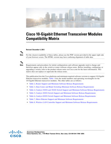
NCV7321Stand-alone LIN TransceiverDescriptionThe NCV7321 is a fully featured local interconnect network (LIN)transceiver designed to interface between a LIN protocol controllerand the physical bus. The transceiver is implemented in I3Ttechnology enabling both high voltage analog circuitry and digitalfunctionality to co exist on the same chip.The NCV7321 LIN device is a member of the in vehiclenetworking (IVN) transceiver family.The LIN bus is designed to communicate low rate data from controldevices such as door locks, mirrors, car seats, and sunroofs at thelowest possible cost. The bus is designed to eliminate as much wiringas possible and is implemented using a single wire in each node. Eachnode has a slave MCU state machine that recognizes and translatesthe instructions specific to that function. The main attraction of theLIN bus is that all the functions are not time critical and usually relateto passenger comfort.Features LIN Compliant to Specification Revision 2.x (BackwardsCompatible to Version 1.3) and J2602 Bus Voltage 45 V Transmission Rate 1 kbps to 20 kbps Supports K Line Bus ArchitectureProtection Thermal Shutdown Indefinite Short Circuit Protection on Pins LIN and WAKETowards Supply and Ground Load Dump Protection (45 V) Bus Pins Protected Against Transients in an AutomotiveEnvironmentEMI Compatibility Integrated Slope ControlModes Normal Mode: LIN Transceiver Enabled, Communication via theLIN Bus is Possible, INH Switch is On Sleep Mode: LIN Transceiver Disabled, the Consumption fromVBB is Minimized, INH Switch is Off Standby Mode: Transition Mode reached either after Power up orafter a Wake up Event, INH Switch is on Wake up Bringing the Component from Sleep Mode into StandbyMode is Possible either by LIN Command or a Digital Signal onWAKE Pin (e.g. External Switch)QualityUnique Site and Control Change Require ments; AEC Q100Qualified and PPAP CapableThese Devices are Pb Free, Halogen Free/BFR Free and are RoHSCompliant Semiconductor Components Industries, LLC, 2016August, 2016 Rev. 148NV7321 xFALYWGSOIC 8CASE 7518111NV7321 yALYWGGDFN8CASE 506DGSOIC 8:x Specific Device Code0 NCV7321D101 NCV7321D112 NCV7321D12DFN8:y Specific Device Code2 NCV7321MW2F Fab Location Code (NCV7321D11R2G only)A Assembly LocationL Wafer LotY YearW Work WeekG Pb Free Package(Note: Microdot may be in either location)PIN CONNECTIONSRxDENWAKETxD182736451INHVBBLINGNDSOIC 8 (Top View)RxD 18 INHEN 2WAKE 3 NCV Prefix for Automotive and Other Applications Requiring MARKINGDIAGRAMS1 LIN Bus Transceiver www.onsemi.comTxD 4EP7 VBB6 LIN5 GNDDFN8 (Top View)ORDERING INFORMATIONSee detailed ordering and shipping information in the packagedimensions section on page 12 of this data sheet.Publication Order Number:NCV7321/D
NCV7321RECOMMENDED OPERATING RANGES AND KEY TECHNICAL CHARACTERISTICSTable 1. RECOMMENDED OPERATING RANGES AND KEY TECHNICAL 7VNominal Battery Operating Voltage (Note 1)Load Dump Protection45IBB SLPSupply Current in Sleep Mode20mAVLINLIN Bus Voltage 4545VVWAKEOperating DC Voltage on WAKE Pin0VBBV 3545VMaximum Rating Voltage on WAKE PinVINHOperating DC Voltage on INH Pin0VBBVV Dig IOOperating DC Voltage on Digital IO Pins (EN, RxD, TxD)05.5VTJSDJunction Thermal Shutdown Temperature150185 CTambOperating Ambient Temperature 40 125 CVESDElectrostatic Discharge Voltage (all pins) Human Body Model (Note 2) 4 4kVVersion NCV7321D11/D12/MW2; no filter on LINElectrostatic Discharge Voltage (LIN) System Human Body Model (Note 3) 10 10kVVersion NCV7321D12/MW2;Voltage transients (DCC method), pin LINAccording to SAE J2962 1, Class C (Note 4) 85 85VVTRAN165Functional operation above the stresses listed in the Recommended Operating Ranges is not implied. Extended exposure to stresses beyondthe Recommended Operating Ranges limits may affect device reliability.1. Below 5 V on VBB in normal mode, the bus will either stay recessive or comply with the voltage level specifications and transition timespecifications as required by SAE J2602. It is ensured by the battery monitoring circuit. Above 27 V on VBB, LIN communication is operational(LIN pin toggling) but parameters cannot be guaranteed. For higher battery voltage operation above 27 V, LIN pull up resistor must beselected large enough to avoid clamping of LIN pin by voltage drop over external pull up resistor and LIN pin min current limitation.2. Equivalent to discharging a 100 pF capacitor through a 1.5 kW resistor conform to MIL STD 883 method 3015.7.3. Equivalent to discharging a 150 pF capacitor through a 330 W resistor. System HBM levels are verified by an external test house.4. Direct Capacitor Coupling (DCC) method according to SAE J2962 1 specification, referring to ISO 7637 3 Slow Transient Pulse. CouplingCapacitor 10 nF. Tested with no external protections. Verified by an external test house.Table 2. THERMAL CHARACTERISTICSSymbolValueUnitThermal characteristics, SOIC 8 (Note 5)Thermal Resistance Junction to Air, Free air, 1S0P PCB (Note 6)Thermal Resistance Junction to Air, Free air, 2S2P PCB (Note 7)ParameterRqJARqJA12575 C/W C/WThermal characteristics, DFN8 (Note 5)Thermal Resistance Junction to Air, Free air, 1S0P PCB (Note 6)Thermal Resistance Junction to Air, Free air, 2S2P PCB (Note 7)RqJARqJA14047 C/W C/W5. Refer to ELECTRICAL CHARACTERISTICS, RECOMMENDED OPERATING RANGES and/or APPLICATION INFORMATION for SafeOperating parameters.6. Values based on test board according to EIA/JEDEC Standard JESD51 3, signal layer with 10% trace coverage.7. Values based on test board according to EIA/JEDEC Standard JESD51 7, signal layers with 10% trace coverage.www.onsemi.com2
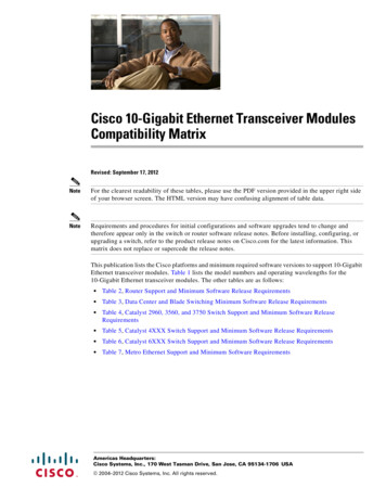
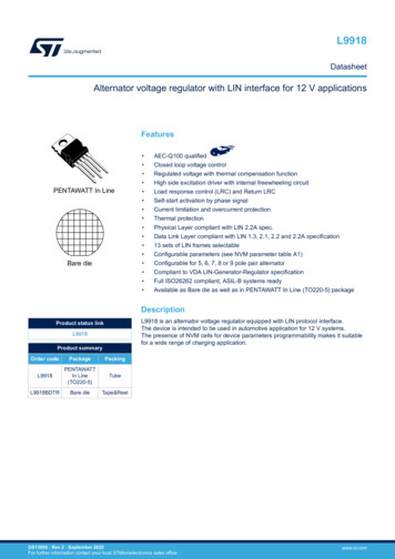
NCV7321BLOCK DIAGRAMVBBINHPORVBBState&Wake upControlWAKEThermalshutdownENOscCOMP RxD TxDFilterLINSlope Controltime outNCV7321GNDFigure 1. Block DiagramTYPICAL APPLICATIONbatECUVBATLINWAKELIN 6WAKE37NCV7321INH 853.3/5VVCC1 RxD4 TxD2ENGNDGNDMicrocontrollerVBBGNDKL30LIN BUSKL31Figure 2. Typical Application Diagram for a Master NodeTable 3. PIN DESCRIPTIONPinNameDescription1RxDReceive Data Output; Low in Dominant State; Open Drain Output2ENEnable Input, Transceiver in Normal Operation Mode when High, Pull down Resistor to GND3WAKE4TxDTransmit Data Input, Low for Dominant State, Pull down to GND (Switchable Strength for Wake up Source Recognition)5GNDGround6LINLIN Bus Output/Input7VBBBattery Supply Input8INHInhibit Output, Switch Between INH and VBB can be Used to Control External Regulator or Pull up Resistor on LIN Bus EPExposed Pad. Recommended to connect to GND or left floating in application (DFN8 package only).High Voltage Digital Input Pin to Apply Local Wake up, Sensitive to Falling Edge, Pull up Current Source to VBBwww.onsemi.com3
NCV7321Table 4. ABSOLUTE MAXIMUM RATINGSMaxUnitVBBSymbolVoltage on Pin VBB 0.3 45VVLINLIN Bus Voltage 45 45VVWAKEDC Voltage on WAKE Pin 35 45VVINHDC Voltage on INH Pin 0.3VBB 0.3VIINHDC Current from INH Pin50mAV Dig IODC Input Voltage on Pins (EN, RxD, TxD) 0.3 45VTJMaximum Junction Temperature 40 150 CVESDHBM (All Pins) (Note 8) 4 4kVCDM (All Pins) (Note 9)VTRANParameterMinTyp 750 750VVersion NCV7321D10:HBM (LIN, INH, VBB, WAKE) (Note 10)System HBM (LIN, VBB, WAKE) (Note 11) 5 5 5 5kVkVVersion NCV7321D11/D12/MW2:HBM (LIN, INH, VBB, WAKE) (Note 10)System HBM (VBB, WAKE) (Note 12)System HBM (LIN) (Note 12) 8 6 10 8 6 10kVkVkVVersion NCV7321D12/MW2:Powered ESD (LIN), Contact/Air, 330 pF / 2 kW (Note 13)Powered ESD (LIN), Air, 150 pF / 2 kW (Note 13) 15 25 15 25kVkV 85 85VVersion NCV7321D12/MW2;Voltage transients (DCC method), pin LINAccording to SAE J2962 1, Class C (Note 14)Stresses exceeding those listed in the Maximum Ratings table may damage the device. If any of these limits are exceeded, device functionalityshould not be assumed, damage may occur and reliability may be affected.8. Equivalent to discharging a 100 pF capacitor through a 1.5 kW resistor conform to MIL STD 883 method 3015.7.9. Charged device model test according to ESD STM5.3.1 1999.10. Equivalent to discharging a 100 pF capacitor through a 1.5 kW resistor referenced to GND.11. Equivalent to discharging a 150 pF capacitor through a 330 W resistor. 220 nF filter on LIN pin. System HBM levels are verified by an externaltest house.12. Equivalent to discharging a 150 pF capacitor through a 330 W resistor. No filter on LIN pin. System HBM levels are verified by an externaltest house.13. Powered ESD test method according to SAE J2962 1 specification, referring to ISO 10605. Verified by an external test house.14. Direct Capacitor Coupling (DCC) method according to SAE J2962 1 specification, referring to ISO 7637 3 Slow Transient Pulse. CouplingCapacitor 10 nF. Tested with no external protections. Verified by an external test house.www.onsemi.com4
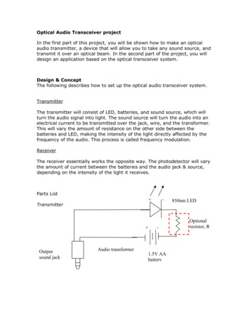
NCV7321FUNCTIONAL DESCRIPTIONOverall Functional DescriptionThe junction temperature is monitored via a thermalshutdown circuit that switches the LIN transmitter off whentemperature exceeds the TSD trigger level.The NCV7321 has four operating states (unpoweredmode, standby mode, normal mode and sleep mode) that aredetermined by the supply voltage VBB, input signals EN andWAKE and activity on the LIN bus.LIN is a serial communication protocol that efficientlysupports the control of mechatronic nodes in distributedautomotive applications. The domain is class A multiplexbuses with a single master node and a set of slave nodes.The NCV7321 contains the LIN transmitter, LIN receiver,power on reset (POR) circuits and thermal shutdown(TSD). The LIN transmitter is optimized for the maximumspecified transmission speed of 20 kB with EMCperformance due to reduced slew rate of the LIN output.OPERATING STATESStandby modeNormal mode LIN Transceiver: OFF LIN Term: 30 kW INH Pin High RxD: Low After a Wake up/Floating Otherwise TxD: Wake up Source FlagEN High for t T enable LIN Transceiver: ON LIN Term: 30 kW INH Pin: High RxD: Received LIN Data TxD: Weak Pull downTransmitter InputLIN Wake Up or Local Wake UpVBB Above Reset LevelEN Low for t T disableEN High for t T enableSleep ModeUnpowered(VBB Below Reset Level) LIN Transceiver: OFF LIN Term: Floating INH Pin: Floating RxD: Floating TxD: Weak Pull down LIN Transceiver: OFF LIN Term: Current Source INH Pin: Floating RxD: Floating TxD: Weak Pull downFigure 3. State DiagramUnpowered Modehigh impedant and the pull down applied on pin TxDremains weak. After a wake up event is recognized while the chip wasin the sleep mode. Pin RxD is pulled low while pinTxD signals the type of wake up leading to the standbymode – its pull up remains weak for LIN wake up andit is switched to strong pull down for the case of localwake up (i.e. wake up via Pin WAKE).While in the standby mode, the configuration of Pins RxDand TxD remains unchanged, regardless the activity onWAKE and LIN Pins – i.e. if additional wake ups occurduring the standby mode, they have no influence on the chipconfiguration.As long as VBB remains below its power on reset level,the chip is kept in a safe unpowered state. LIN transmitter isinactive, both LIN and INH pins are left floating and only aweak pull down is connected on pin TxD. Pin RxD remainsfloating.The unpowered state will be entered from any other statewhen VBB falls below its power on reset level.Standby ModeStandby mode is a low power mode, where LINtransceiver remains inactive while INH pin is driven high toactivate an external voltage regulator – see Figure 2.Depending on the transition which led to the standby mode,pins RxD and TxD are configured differently during thismode. A 30 kW resistor in series with a reverse protectiondiode is internally connected between LIN and VBB Pins.Standby mode is entered in one of the following ways: After the voltage level at VBB pin rises above itspower on reset level. In this case, RxD Pin remainsNormal ModeIn normal mode, the full functionality of the LINtransceiver is available. Data according the state of TxDinput are sent to the LIN bus while pin RxD reflects thelogical symbol received on the LIN bus – high impedant forrecessive and Low for dominant. A 30 kW resistor in serieswww.onsemi.com5
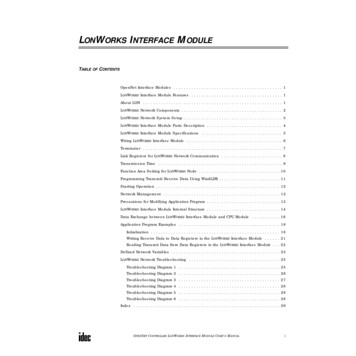
NCV7321the chip in the normal mode (e.g. strong pull down on TxDafter local wake up vs. High logical level on TxD requiredto send a recessive symbol on LIN).with a reverse protection diode is internally connectedbetween LIN and VBB pins.To avoid that, due to a failure of the application (e.g.software error), the LIN bus is permanently driven dominantand thus blocking all subsequent communication, signal onpin TxD passes through a timer, which releases the bus incase TxD remains low for longer than T TxD timeout. Thetransmission can continue once the TxD returns to Highlogical level.In case the junction temperature increases above thethermal shutdown threshold, e.g. due to a short of the LINwiring to the battery, the transmitter is disabled and releasesLIN bus to recessive. Once the junction temperaturedecreases back below the thermal shutdown release level,the transmission can be enabled again – however, to avoidthermal oscillations, first a High logical level on TxD mustbe encountered before the transmitter is enabled.As required by SAE J2602, the transceiver must behavesafely below its operating range – it shall either continue totransmit correctly (according its specification) or remainsilent (transmit a recessive state regardless of the TxDsignal). A battery monitoring circuit in NCV7321de activates the transmitter in the normal mode if the VBBlevel drops below MONL VBB. Transmission is enabledagain when VBB reaches MONH VBB. The internal logicremains in the normal mode and the reception from the LINline is still possible even if the battery monitor disables thetransmission. Although the specifications of the monitoringand power on reset levels are overlapping, it’s ensured bythe implementation that the monitoring level never fallsbelow the power on reset level.Normal mode can be entered from either standby or sleepmode when EN Pin is High for longer than T enable. Whenthe transition is made from standby mode, TxD pull downis set to weak and RxD is put high impedant immediatelyafter EN becomes High (before the expiration of T enablefiltering time). This excludes signal conflicts between thestandby mode pin settings and the signals required to controlWAKEVBBSleep ModeSleep mode provides extremely low current consumption.The LIN transceiver is inactive and the battery consumptionis minimized. Pin INH is put to high impedant state todisable the external regulator and, in case of a master node,the LIN termination – see Figure 2. Only a weak pull upcurrent source is internally connected between LIN andVBB Pins, in order to minimize current consumption even incase of LIN short to GND.Sleep mode can be entered from normal mode byassigning Low logical level to pin EN for longer thanT disable. The sleep mode can be entered even if apermanent short occurs either on LIN or WAKE Pin.If a wake up event occurs during the transition betweennormal and sleep mode (during the T disable filtering time),it will be regarded as valid wake up and the chip will enterstandby mode with the appropriate setting of Pins RxD andTxD.Wake upTwo types of wake up events are recognized by NCV7321: Local wake up – when a high to low transition on pinWAKE is encountered and WAKE pin remains Low atleast during T WAKE – see Figure 4. Remote (or LIN) wake up – when LIN bus isexternally driven dominant during longer thanT LIN wake and a rising edge on LIN occursafterwards – see Figure 5.Wake up events can be exclusively detected in sleep modeor during the transition from normal mode to sleep mode.Due to timing tolerances, valid wake up events beginningshortly before normal to sleep mode transition can be alsosometimes regarded as valid wake ups.Local Wake up recognizedT WAKEV WAKE thSleep ModeStandby ModeFigure 4. Local Wake up Detectionwww.onsemi.com6t
NCV7321LINDetection of Remote Wake UpVBBLIN recessive levelT LIN wake60% VBBT to stb40% VBBSleep ModeLIN dominant leveltStandby ModeFigure 5. Remote (LIN) Wake up DetectionELECTRICAL CHARACTERISTICSDefinitionsAll voltages are referenced to GND (Pin 5). Positive currents flow into the IC.Table 5. DC CHARACTERISTICS (VBB 5 V to 27 V; TJ 40 C to 150 C; Bus Load 500 W (VBB to LIN); unless otherwisespecified. Typical values are given at VBB 12 V and TJ 25 C, unless otherwise BB CURRENT CONSUMPTIONIBB ON recVBB ConsumptionNormal Mode; LIN RecessiveVLIN VBB VINH VWAKE1.6mAIBB ON domVBB ConsumptionNormal Mode; LIN DominantVBB VINH VWAKE8mAIBB STBVBB ConsumptionStandby ModeVLIN VBB VINH VWAKE350mAIBB SLPVBB ConsumptionSleep ModeVLIN VBB VINH VWAKE30mAIBB SLP 18VVBB ConsumptionSleep Mode, VBB 18 VVLIN VBB VINH VWAKE(Note 15)20mAIBB SLP 12VVBB ConsumptionSleep Mode, VBB 12 V, TJ 85 CVLIN VBB VINH VWAKE(Note 15)10mAPOR AND VBB MONITORPORH VBBPower on Reset HighLevel on VBBVBB Rising24.5VPORL VBBPower on Reset LowLevel on VBBVBB Falling1.74VMONH VBBBattery MonitoringHigh LevelVBB Rising4.5VMONL VBBBattery Monitoring LowLevelVBB FallingLIN Dominant OutputVoltageTxD Low; VBB 7.3 V3VLIN TRANSMITTERVLIN dom LoSup1.2V15. Values based on design and characterization. Not tested in production.16. The voltage drop in Normal mode between LIN and VBB pin is the sum of the diode drop and the drop at serial pull up resistor. The dropat the switch is negligible. See Figure 1.www.onsemi.com7
NCV7321Table 5. DC CHARACTERISTICS (VBB 5 V to 27 V; TJ 40 C to 150 C; Bus Load 500 W (VBB to LIN); unless otherwisespecified. Typical values are given at VBB 12 V and TJ 25 C, unless otherwise .0VVBB 1.5VBBV40200mA3347kW2030pF0.4VBBLIN TRANSMITTERVLIN dom HiSupLIN Dominant OutputVoltageTxD Low; VBB 18 VVLIN RECLIN Recessive OutputVoltage (Note 16)TxD High; ILIN 10 mAILIN limShort Circuit CurrentLimitationVLIN VBB maxRslaveInternal Pull upResistanceCLINCapacitance on PinLIN (Note 15)20LIN RECEIVERVbus domBus Voltage forDominant StateVbus recBus Voltage forRecessive StateVrec domReceiver ThresholdLIN Bus Recessive Dominant0.40.6VBBVrec recReceiver ThresholdLIN Bus Dominant Recessive0.40.6VBBVrec cntReceiver CentreVoltage(Vrec dom Vrec rec)/20.4750.525VBBVrec hysReceiver Hysteresis(Vrec rec Vrec dom)0.050.175VBBILIN off domLIN Output Current,Bus in Dominant StateNormal Mode, Driver Off;VBB 12 V, VLIN 0 V 1ILIN off dom slpLIN Output Current,Bus in Dominant StateSleep Mode, Driver Off;VBB 12 V, VLIN 0 V 20ILIN off recLIN Output Current,Bus in Recessive StateDriver Off;VBB 18 V; VBB VLIN 18 VILIN no GNDCommunication notAffectedVBB GND 12 V; 0 VLIN 18 VILIN no VBBLIN Bus RemainsOperationalVBB GND 0 V; 0 VLIN 18 V0.6VBBmA 15 1 2mA1mA1mA5mAPIN ENVil ENLow Level InputVoltage 0.30.8VVih ENHigh Level InputVoltage2.05.5VRpd ENPull down Resistanceto Ground150650kWVil TxDLow Level InputVoltage 0.30.8VVih TxDHigh Level InputVoltage2.05.5VRpd TxDPull down Resistor onTxD Pin,Corresponding to“Weak Pull down”650kW350PIN TxDNormal Mode or Sleep Mode orStandby Mode after Power up orStandby Mode after LIN Wake up15035015. Values based on design and characterization. Not tested in production.16. The voltage drop in Normal mode between LIN and VBB pin is the sum of the diode drop and the drop at serial pull up resistor. The dropat the switch is negligible. See Figure 1.www.onsemi.com8
NCV7321Table 5. DC CHARACTERISTICS (VBB 5 V to 27 V; TJ 40 C to 150 C; Bus Load 500 W (VBB to LIN); unless otherwisespecified. Typical values are given at VBB 12 V and TJ 25 C, unless otherwise ull down Current onTxD Pin Correspondingto “Strong Pull down”Standby Mode after Local Wake up1.5mAIol RxDLow Level OutputCurrentVRxD 0.4 V, Normal Mode,VLIN 0 V1.5mAIoh RxDHigh Level OutputCurrentVRxD 5 V, Normal Mode,VLIN VBB 5PIN TxDIpd TxD StrongPIN RxD05mAVBB 1.1VPIN WAKEV wake thWAKE ThresholdVoltageVBB 3.3I wake pull upPull up Current on PinWAKEVWAKE 0 V 30 15 1mAI wake leakLeakage of Pin WAKEVWAKE VBB 505mADelta VHHigh Level VoltageDropIINH 15 mA, INH Active0.050.350.75VI leakLeakage CurrentSleep Mode; VINH 0 V 101mATemperature Rising150165185 CPIN INHTHERMAL SHUTDOWNTJSDThermal ShutdownJunction TemperatureTJSD hystThermal ShutdownHysteresis5 C15. Values based on design and characterization. Not tested in production.16. The voltage drop in Normal mode between LIN and VBB pin is the sum of the diode drop and the drop at serial pull up resistor. The dropat the switch is negligible. See Figure 1.www.onsemi.com9
NCV7321Table 6. AC CHARACTERISTICS (VBB 5 V to 27 V; TJ 40 C to 150 C; unless otherwise specified. For the transmitterparameters, the following bus loads are considered: L1 1 kW / 1 nF; L2 660 W / 6.8 nF; L3 500 W / 10 nF)SymbolParameterConditionsMinTypMaxUnitLIN TRANSMITTERD1Duty Cycle 1 tBUS REC(min) /(2 x TBIT)THREC(max) 0.744 x VBBTHDOM(max) 0.581 x VBBTBIT 50 msVBB 7 V to 18 V0.3960.5D2Duty Cycle 2 tBUS REC(max) /(2 x TBIT)THREC(min) 0.422 x VBBTHDOM(min) 0.284 x VBBTBIT 50 msVBB 7.6 V to 18 V0.50.581D3Duty Cycle 3 tBUS REC(min) /(2 x TBIT)THREC(max) 0.778 x VBBTHDOM(max) 0.616 x VBBTBIT 96 msVBB 7 V to 18 V0.4170.5D4Duty Cycle 4 tBUS REC(max) /(2 x TBIT)THREC(min) 0.389 x VBBTHDOM(min) 0.251 x VBBTBIT 96 msVBB 7.6 V to 18 V0.50.590Ttx prop downPropagation Delay ofTxD to LIN. TxD highto low(Note 17)6msTtx prop upPropagation Delay ofTxD to LIN. TxD low tohigh(Note 17)6msT fallLIN Falling EdgeNormal Mode; VBB 12 V22.5msT riseLIN Rising EdgeNormal Mode; VBB 12 V22.5msT symLIN Slope SymmetryNormal Mode; VBB 12 V4ms 40LIN RECEIVERTrec prop downPropagation Delay ofReceiver Falling Edge0.16msTrec prop upPropagation Delay ofReceiver Rising Edge0.16msTrec symPropagation DelaySymmetryTrec prop down Trec prop up 22ms30150msMODE TRANSITIONS AND TIMEOUTST LIN wakeDuration of LINDominant for Detectionof Wake up via LIN busSleep ModeT to stbDelay from LIN BusDominant to RecessiveEdge to Entering ofStandby Mode afterValid LIN Wake upSleep ModeT WAKEDuration of Low Levelon WAKE Pin for LocalWake up DetectionSleep Mode7T enableDuration of High Levelon EN Pin for Tran sition to Normal ModeVersion NCV7321D102Version NCV7321D11/D12/MW2Duration of Low Levelon EN Pin for Tran sition to Sleep ModeTxD DominantTime OutT disableT TxD timeout90ms1050ms510ms27.518.5msVersion NCV7321D102510msVersion NCV7321D11/D12/MW227.518.5msNormal Mode, TxD Low, Guaran tees Baudrate as Low as 1 kbps1550ms17. Values based on design and characterization. Not tested in production.www.onsemi.com10
NCV7321TxDt BITt BIT50%ttBUS DOM(max)LINtBUS REC(min)THREC(max)THDOM(max)Thresholds ofreceiving node 1THREC(min)THDOM(min)Thresholds ofreceiving node 2ttBUS DOM(min)tBUS REC(max)Figure 6. LIN Transmitter Duty CycleTxDtBITtBIT50%tLINVBB60% VBB40% VBBttx prop downtttx prop upFigure 7. LIN Transmitter TimingLIN100%60%60%40%40%0%tT fallT riseFigure 8. LIN Transmitter Rising and Falling Timeswww.onsemi.com11
NCV7321LINVBB60% VBB40% VBBtRxDtrec prop downtrec prop up50%tFigure 9. LIN Receiver TimingDEVICE ORDERING INFORMATIONPart 1R2GDescriptionTemperature Range 40 C to 125 CImproved Stand alone LINTransceiverESD Improved Stand aloneLIN TransceiverShipping†96 Tube / TrayStand alone LINTransceiverSOIC 8(Pb Free)3000 / Tape & Reel96 Tube / Tray3000 / Tape & ReelNCV7321D12R2GNCV7321MW2R2GPackage 40 C to 125 CSOIC 8(Pb Free)3000 / Tape & ReelDFN8Wettable Flank(Pb Free)3000 / Tape & Reel†For information on tape and reel specifications, including part orientation and tape sizes, please refer to our Tape and Reel PackagingSpecifications Brochure, BRD8011/D.www.onsemi.com12
MECHANICAL CASE OUTLINEPACKAGE DIMENSIONSDFN8, 3x3, 0.65PCASE 506DGISSUE A1SCALE 2:1ABDPIN ONEREFERENCE2X0.10 C2XDETAIL AÉÉÉÉÉÉÉÉÉÉÉÉ0.10 CLALTERNATE TERMINALCONSTRUCTIONEAA3SIDE VIEWSEATINGPLANE1D2DETAIL A18XCA14Le/2858Xb0.10 C A BeBOTTOM VIEW0.05 C*This information is generic. Please referto device data sheet for actual partmarking.Pb Free indicator, “G” or microdot “ G”,may or may not be present.NOTE 3RECOMMENDEDSOLDERING XXXXALYWGGXXXXXX Specific Device CodeA Assembly LocationL Wafer LotY YearW Work WeekG Pb Free Package(Note: Microdot may be in either location)E2KMILLIMETERSMINMAX0.801.000.000.050.20 REF0.250.353.00 BSC2.302.503.00 BSC1.501.700.65 BSC0.30 TYP0.350.45GENERICMARKING DIAGRAM*0.05 CNOTE 4NOTES:1. DIMENSIONING AND TOLERANCING PERASME Y14.5M, 1994.2. CONTROLLING DIMENSION: MILLIMETERS.3. DIMENSION b APPLIES TO PLATED TERMINALAND IS MEASURED BETWEEN 0.15 AND0.30mm FROM THE TERMINAL TIP.4. COPLANARITY APPLIES TO THE EXPOSEDPAD AS WELL AS THE TERMINALS.DIMAA1A3bDD2EE2eKLTOP VIEW0.05 CDATE 28 APR 20168X0.603.308X0.40DIMENSIONS: MILLIMETERS*For additional information on our Pb Free strategy and solderingdetails, please download the ON Semiconductor Soldering andMounting Techniques Reference Manual, SOLDERRM/D.DOCUMENT NUMBER:DESCRIPTION:98AON10527GDFN8 3X3, 0.65PElectronic versions are uncontrolled except when accessed directly from the Document Repository.Printed versions are uncontrolled except when stamped “CONTROLLED COPY” in red.PAGE 1 OF 1ON Semiconductor andare trademarks of Semiconductor Components Industries, LLC dba ON Semiconductor or its subsidiaries in the United States and/or other countries.ON Semiconductor reserves the right to make changes without further notice to any products herein. ON Semiconductor makes no warranty, representation or guarantee regardingthe suitability of its products for any particular purpose, nor does ON Semiconductor assume any liability arising out of the application or use of any product or circuit, and specificallydisclaims any and all liability, including without limitation special, consequential or incidental damages. ON Semiconductor does not convey any license under its patent rights nor therights of others. Semiconductor Components Industries, LLC, 2019www.onsemi.com
MECHANICAL CASE OUTLINEPACKAGE DIMENSIONSSOIC 8CASE 751AZISSUE B81SCALE 1:1NOTES 4&50.10 C D45 5 CHAMFERDhNOTE 6DA8DATE 18 MAY 2015H2X50.10 C DEE1NOTES 4&5L210.20 C D48XBNOTE 6TOP VIEWb0.25MLCDETAIL AC A-B DNOTES 3&7NOTE 7c0.10 CeA1CSIDE VIEWNOTE 8DIMAA1A2bcDEE1ehLL2DETAIL AA2ASEATINGPLANENOTES:1. DIMENSIONING AND TOLERANCING PER ASME Y14.5M, 1994.2. CONTROLLING DIMENSION: MILLIMETERS.3. DIMENSION b DOES NOT INCLUDE DAMBAR PROTRUSION.ALLOWABLE PROTRUSION SHALL BE 0.004 mm IN EXCESS OFMAXIMUM MATERIAL CONDITION.4. DIMENSION D DOES NOT INCLUDE MOLD FLASH, PROTRUSIONSOR GATE BURRS. MOLD FLASH, PROTRUSIONS OR GATE BURRSSHALL NOT EXCEED 0.006 mm PER SIDE. DIMENSION E1 DOESNOT INCLUDE INTERLEAD FLASH OR PROTRUSION. INTERLEADFLASH OR PROTRUSION SHALL NOT EXCEED 0.010 mm PER SIDE.5. THE PACKAGE TOP MAY BE SMALLER THAN THE PACKAGE BOT TOM. DIMENSIONS D AND E1 ARE DETERMINED AT THE OUTER MOST EXTREMES OF THE PLASTIC BODY AT DATUM H.6. DIMENSIONS A AND B ARE TO BE DETERMINED AT DATUM H.7. DIMENSIONS b AND c APPLY TO THE FLAT SECTION OF THE LEADBETWEEN 0.10 TO 0.25 FROM THE LEAD TIP.8. A1 IS DEFINED AS THE VERTICAL DISTANCE FROM THE SEATINGPLANE TO THE LOWEST POINT ON THE PACKAGE BODY.SEATINGPLANEEND VIEWRECOMMENDEDSOLDERING 10.510.100.254.90 BSC6.00 BSC3.90 BSC1.27 BSC0.250.410.401.270.25 BSCGENERICMARKING NSIONS: MILLIMETERS*For additional information on our Pb Free strategy and solderingdetails, please download the ON Semiconductor Soldering andMounting Techniques Reference Manual, SOLDERRM/D.DOCUMENT NUMBER:DESCRIPTION:98AON34918ESOIC 8XXXXXALYWXG Specific Device Code Assembly Location Wafer Lot Year Work Week Pb Free Package*This information is generic. Please referto device data sheet for actual partmarking. Pb Free indicator, “G”, mayor not be present.Electronic versions are uncontrolled except when accessed directly from the Document Repository.Printed versions are uncontrolled except when stamped “CONTROLLED COPY” in red.PAGE 1 OF 1ON Semiconductor andare trademarks of Semiconductor Components Industries, LLC dba ON Semiconductor or its subsidiaries in the United States and/or other countries.ON Semiconductor reserves the right to make changes without further notice to any products herein. ON Semiconductor makes no warranty, representation or guarantee regardingthe suitability of its products for any particular purpose, nor does ON Semiconductor assume any liability arising out of the application or use of any product or circuit, and specificallydisclaims any and all liability, including without limitation special, consequential or incidental damages. ON Semiconductor does not convey any license under its patent rights nor therights of others. Semiconductor Components Industries, LLC, 2019www.onsemi.com
onsemi,, and other names, marks, and brands are registered and/or common law trademarks of Semiconductor Components Industries, LLC dba “onsemi” or its affiliatesand/or subsidiaries in the United States and/or other countries. onsemi owns the rights to a number of patents, trademarks, copyrights, trade secrets, and other intellectual property.A listing of onsemi’s product/patent coverage may be accessed at www.onsemi.com/site/pdf/Patent Marking.pdf. onsemi reserves the right to make changes at any time to anyproducts or information herein, without notice. The information herein is provided “as is” and onsemi makes no warranty, representation or guarantee regarding the accuracy of theinformation, product features, availability, functionality, or suitability of its products for any
automotive applications. The domain is class A multiplex buses with a single master node and a set of slave nodes. The NCV7321 contains the LIN transmitter, LIN receiver, power on reset (POR) circuits and thermal shutdown (TSD). The LIN transmitter is optimized for the maximum specified transmission speed of 20 kB with EMC