Transcription
NEW AOVANCES INVEHICULAR TECHNOLOGYANO AUTOMOTIVEENGINEERINGEdited by Joao Paulo Carmoand Joao Eduardo RibeiroI NTECHOPEN .COM
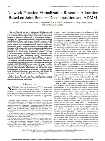
New Advances in Vehicular Technology and Automotive Engineeringhttp://dx.doi.org/10.5772/2617Edited by Joao Paulo Carmo and Joao Eduardo RibeiroContributorsMohsen Mohseni, Bahram Ramezanzadeh, Hossein Yari, Mohsen Moazzami Gudarzi, HorstHintze-Bruening, Fabrice Leroux, Evripidis Lois, Panagiotis Arkoudeas, Amaya 19artua, XanaFdez-Pérez. lfiaki IIlarramendi, Rolf Luther, Jürgen Rausch, Mathias Woydt, Vítor Monteiro,Henrique Gonçalves, João C. Ferreira, João L Afonso. Ruben Ivankovic, Jérôme eras, MehdiTaghizadeh Kakhki, Carlos A. Martins, Philippe Viarouge, Niels Koeh, Preeti Bajaj, MilindKhanapurkar, Amedeo Trajano, Eros Pasero, Luca Mesin, 1. P. Carmo, 1. E. Ribeiro, HernaniLopes, João Ribeiro, Arjun Yogeswaran, Pierre payeur, Darrell Robinette, (arl Anderson, lasonBlough, Takama Suzuki, Masaki Ta kahashi, Mário Sacomano Neto, Sílvio R. I. PiresPublished by InTechJaneza Trdine 9,51000 Rijeka, CroatiaCopyright 2012 InTechAli chapters are Open Access distributed under the Creative Commons Attribution 3.0 license,wh ich allows users to download, copy and build upon published articles even for commercialpurposes, as long as the author and publisher are properly cred ited, which ensures maximumdissemination and a wider impact of our publications. After this work has been published byInTech, authors have the right to republish it, in whole or part, in any publication of which theyare the author, and to make other personal use of the work. Any republication, referencing orpersonal use of the work must explicitly identify the original source.NoticeStatements and opinions expressed in the chapters are these of the individual contributors andnot necessarily those of the editors or publisher. No responsibility is accepted for the accuracyof information contained in the published chapters. The publisher assumes no responsibility forany damage or injury to persons or property arising out of the use of any materiais,instructions, methods or ideas contained in the book.Publishing Process Manager Mima CvijicTypesetting InTech Prepress, Novi SadCever InTeeh Design TeamFirst published Ju ly, 2012Printed in CroatiaA free online edition of t his book is available at www.intechopen.eomAdditional hard copies can be obtained from orders@intechopen.comNew Advances in Vehicular Teehnology and Automotive Engineering, Edited by JoaoPaulo Carmo and Joao Eduardo Ribeirop. em.ISBN 978-953-51-0698-2INTECHopen science I open mindsfree online edjtjons of InTechBooks and Journals can be found atwww.intechopen.com
ContentsPrefaceIXSection 1Materiais1Chapter 1The Role of Nanotechnology in Automotive IndustriesMohsen Mohseni, Bahram Ramezanzadeh,Hossein Yari and Mohsen Moazzami GudarziChapter 2Nanocomposite Based Multifunctional CoatingsHorst Hintze-Bruening and Fabrice LerauxChapter 3Lubricating Aspects of Automotive FuelsEvripidis Lois and Panagiotis ArkoudeasChapter 4Biolubricants and TriboreactiveMateriais for Automotive Applications 119Amaya Igartua, Xana Fdez-Pérez, lriaki IIlarramendi,Rolf Luther, Jürgen Rausch and Mathias WoydtSectian 2ElectranicsChapter 5Batteries Charging Systems for Electricand Plug-In Hybrid Electric Vehicles 149Vítor Monteiro, Henrique Gonçalves,João C. Ferreira and João L. AfonsoChapter 6Power Electronic Solutions to Improve thePerformance of Lundell Automotive Alternators 169Ruben Ivankovic, Jérôme Cras, Mehdi Taghizadeh Kakhki,Carlos A. Martins and Philippe ViaraugeChapter 7Antennas for AutomobilesNiels Koch55911471913
VIContentsChapter 8Chapter 9Chapter 10Section 3Chapter 11Automotive Networks BasedIntra-Vehicular Communication ApplicationsPreeti Bajaj and Milind Khanapurkar207A Road Ice Sensor 231Amedeo Trojano, Eros Pasero and Luca MesinOptical Techniques for Defect Evaluation in VehiciesJ. P. Carmo and J. E. RibeiroMechanics283Structural Health Monitoring inComposite Automotive ElementsHernani Lopes and João Ribeiro285Chapter 123D Surface Analysis for Automated Detectionof Deformations on Automotive Body Panels 303Arjun Yogeswaran and Pierre PayeurChapter 13Development of a Dimensionless Model for Predictingthe Onset of Cavitation in Torque Converters 333Darrell Robinette, Carl Anderson and Jason BloughChapter 14Semi-Active Suspension Control ConsideringLateral Vehicie Dynamics Due to Road Input 359Takama Suzuki and Masaki TakahashiSection 4Chapter 15Manufacturing377Performance Measurement in SupplyChains: A Study in the Automotive Industry 379Mário Sacomano Neto and Silvio R. I. Pires255
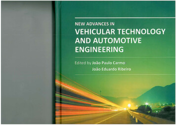
Chapter 10Optical Techniquesfor Defect Evaluation in VehiclesJ. P. Carmo and J. E. RibeiroAdditional information is available at the end of the chapterhttp://dx.doi.org/10.5772/461081. IntroductionThe optical techniques are a powerful tool on situations where either the physical contact orinvasive techniques for evaluation are not suitable. Vehicle environments constitute anapplication field for the optical techniques and are the focus of this chapter. In order toreinforce this kind of techniques, it must be clarified that the idea to manipulate the light backsto the second century before our age, when Archimedes planned to destroy enemy ships usinga solar heat ray with an array of actuators to change the shape of a mirror (Bifano T., 2011).Therefore, the field of photonics is the one that offers the possibility to achieve one of thegreatest realizations and applications because the light is present in all aspects of the humanlife and our way of living is impossible without light (Carmo J. P. et al., 2012a). Opticalmeasurement systems are also suitable for harsh monitorization because they are non-contactand full-field techniques. This is the case of Moiré Interferometry, which is used for manyoptoelectronic applications as displacement measurements (Wronkowski L., 1995), evaluationof microelectronics devices deformation (Xie H. et al., 2004), optical communications (Chen L.et al., 2000), strain measurements with Fiber Bragg Grattings, FBGs, (Silva A. F. et al., 2011) andspectrography (Kong S. H. et al., 2001). In this context, it must be noted that the recent nucleardisaster in Fukushima, Japan, confirms the need of tighter security measures be done withinharsh environments (which includes the automobiles) in order to increase both the safety ofpeople and the reliability of vehicles’ parts.2. Principles of full-field optical techniques2.1. Holographic interferometryThe holography is a method to store and regenerate all the amplitude and phaseinformation contained in the light which is scattered from an illuminated object. Thistechnology offers the possibility of three dimension photography. 2012 Carmo and Ribeiro, licensee InTech. This is an open access chapter distributed under the terms ofthe Creative Commons Attribution License (http://creativecommons.org/licenses/by/3.0), which permitsunrestricted use, distribution, and reproduction in any medium, provided the original work is properly cited.
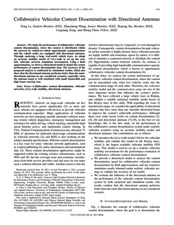
256 New Advances in Vehicular Technology and Automotive EngineeringDespite the holography requires coherent light, it was discovered by Gabor in 1948 (GaborD., 1948), more than a decade before the invention of the laser, which in 1960. By means ofholography an original wave field can be reconstructed at a later time at a different location.This technique therefore has many potential applications.In the year of 1965, when the CW lasers became available, Robert Powell and Karl Stetsonpublished the first work on holographic interferometry (Powel R. L. et al., 1965). Using thistechnique, it is possible record the precise shape and position of a object in two differentstates, then it is possible compare the two records to measure the movement or deformation,that were displayed as fringes on the image.In the Figure 1 is shown the optical set-up of holography.L1BSlaserL2objectRWOWfilm plateFigure 1. Holography configuration to measure the surface displacement.The laser beam is divided in two beams using a beam splitter (BS). Each of one is opened bytwo lenses (L1 and L2), on film plate is recorded the interference of two coherent wavefronts:the object (OW) and reference (RW). When the film plate is developed and then illuminatedby the reference wavefront, it will be reconstructed a virtual image of the original object. Themost used technique for displacement measurement is double exposure or frozen-fringe,which records two holograms on the same film plate, the first one is corresponding to aninitial condition of the object and the second one to a displaced or charged condition. Theimage is reconstructed by a coherent beam illumination; the two reconstructed images willinterfere, resulting in a holographic fringe pattern that can be used to measure surfacedisplacements. Each fringe represents a contour of equal displacement of the object, wherethe value of displacement is one-half the wavelength of the light source used in therecording process (Shang H. et al., 2009).There are others holographic interferometry techniques in which the most relevant are realtime live-fringe and time-average holographic interferometry. The real-time approachrequires that the photographic plate must be physically developed in place withoutchanging its position. The single-exposure hologram is made in the regular way and after itis illuminated by the reference beam while the object is illuminate by the original objectbeam (Cloud G., 1988). The time-average holographic interferometry approach is used for
Optical Techniques for Defect Evaluation in Vehicles 257modal analysis of vibrating bodies. A hologram of the moving body is made with anexposure time lasting over numerous periods of the vibrational motion.Recent advances in recording materials, lasers and computer allowed more holographytechniques being developed, which include: TV holography, digital holography anddynamic holographic interferometry. These techniques open new and challenge fields ofresearch and applications. Nevertheless, this technique has some drawbacks like thedisplacement components cannot be measured independently in different planes. Anotherlimitation is the strict requirement of vibration (half a wavelength of the illuminatingsource), if the vibration magnitude is higher occurs decorrelation. As a result, its industrialapplication as a routine Non Destructive Testing (NDT) technique is restrict, usually thesetechniques are used in laboratory environment.2.2. Electronic speckle pattern interferometryElectronic speckle pattern interferometry is a NDT technique which basic concepts weresimultaneously developed Mavsky et al (Macovsky A. et al., 1971) in United States and byButters and Leendertz (Butters J. et al., 1971; Butters N. et al., 1975) in England. Later grouppursued the development of the ESPI technique, with Lökberg (Lökberg O. et al., 1976;Lökberg O., 1985) and Beidermann (Beidermann et al., 1975) being important references inthis field.Speckle techniques use the random pattern of dark and bright spots (speckles) that areformed in space when a diffusely reflecting object is illuminated by coherent laser light(laser speckles). A random granular pattern called a speckle pattern is observed whenlooking, with the eye or with a camera, at a object surface when it is illuminated by alaser - see the Figures 2(a) and (b). The speckles appear only if the surface roughness isgreater than the wavelength, λ, of the light. If the object is imaged, each point P on thedetector will gain contribution of light coming from a coherence volume, determined by atleast the airy spot and the roughness of the surface (Svanbro A., 2005).The observed speckle pattern unrepeatable for each illuminated area in the sense that theobserved pattern is unique for the microstructure of the specific surface area. Anotherregion will give rise to a totally different random speckle pattern. The speckle pattern isrecords by a CCD camera and could interfere with a reference wave. If the object suffers adeformation caused by an external load, the speckle pattern will change due the variation ofwavefront between the object and reference waves. This deformation could be computedusing an operation of digital subtracting between the speckle patterns corresponding tobefore deformation from the one after deformation. This operation will result in aninterferogram, which will be displayed on the monitor as a pattern of dark and brightfringes that are called correlation fringes. ESPI allows displacements in different directionsto be measured separately with a high-resolution.ESPI technique can be sensitive to out-of-plane or in-plane displacement, depending of theused optical set-up. For in-plane displacement measurement (Figure 3), the object lies in the
258 New Advances in Vehicular Technology and Automotive b)Figure 2. (a) The schematic representation of speckle formation and (b) a typical speckle pattern.Figure 3. A schematic presentation of the optical set-ups used in-plane ESPI (Jones R. et al., 1974). LA:laser source, BS: beam splitter, M1 and M2: plane mirrors, L: lens, TS: test specimen or object.
Optical Techniques for Defect Evaluation in Vehicles 259xy-plane and is illuminated by two plane wavefronts, inclined at equal and opposite angles,θ, to the x-axis surface-normal. No separate reference beam is needed at the image plane.The positive y-axis points out of the page, and the center of the viewing lens aperture lies onthe z-axis. The phase change Δ of the wavefront from the object surface before and afterdeformation can be expressed as: 4 sin( )U (1)where λ is the wavelength of the laser, θ the incident angle, and U is the in-planedisplacement component.For out-of-plane displacement measurement, the object is illuminated by an object which isviewed by a CCD camera (Figure 4). A reference speckle pattern formed by a referencebeam is also observed by the camera. So the resultant image is the interference of these twospeckle patterns.BS1MlaserL1L1CCDBS2objectL2Figure 4. ESPI sensitive to out-of-plane displacement. Where BS1,2: beam splitter; M: plane mirror; L1:concave lens; L2: convex lens.The relation between the phase change and the deformation can be expressed as: 2 1 cos( ) W (2)where W is the out-of-plane displacement component2.3. ShearographyShearography technique is particularly interesting because it enables direct measurementsof displacement derivatives which are related to the strains (Hung Y. et al., 1973; Leendertz,J. A. et al., 1973).
260 New Advances in Vehicular Technology and Automotive EngineeringThe basic principle of shearography, is to carry the rays scattered from one point of theobject into interference with those from a adjacent point. To obtained this interference isused a speckle-shearing interferometric camera like the represented in the Figure 5. Theoptical set-up is similar as that used in common speckle photography, however one half ofthe camera lens is covered by a thin glass wedge. Thus, the two images focused by each halfof the lens are laterally sheared one to other (Gåsvik K. J. et al., 2002). The shearing directionis oriented by the wedge position and it is proportional to its angle. If the shearing is in the xdirection, the rays from a point P(x,y) on the object will interfere in the image plane withthose from a neighboring point P(x δx,y).θxP(x δx,y)δxP(x,y)zzobjectFigure 5. The optical set-up of shearography.When the object is deformed there is a relative displacement between the two points thatproduces a relative optical phase change is given by: 1 cos( ) w( x x , y) w( x , y) k sin( ) u( x x , y ) u( x , y ) (3)where θ is the angle of incidence and u and w are the displacement components in the x-andz-directions, respectively. If the shear δx is very small, the relative displacements may beapproximated by the displacement derivatives and thus Equation (3) becomes: k{ 1 cos( ) w u sin( ) } x x x(4)By rotating the camera 90º around the z-axis, u in Equation (4) is replaced by v, thedisplacement component in the y-direction.2.4. Moiré methodsThe word Moiré derives from the French term meaning wet silk or fringe patterns producedby the interference of aligned fibers in thin tissues. In Engineering, Moiré refers to atechnique for experimental analysis for determining the displacement or deformation from a
Optical Techniques for Defect Evaluation in Vehicles 261set of interference fringes resulting from the superposition of two systems - one in thedeformed specimen and the other that is undeformed can be used as reference. Moirétechniques have appeared in the field of optics since nineteenth century (Rayleigh L., 1874).The Moiré techniques allow the measurement of deformations which occur when an objectis subjected to applied charges. These methods can measure out-of-plane and in-planedisplacements. The displacements are measured simultaneously over the whole view fieldand the measurement data are exposed as contour maps of displacements. One of mostimportant Moiré method is the Moiré interferometry that was performed by Post (Post D. etal., 1994) in 1980 and represents one the most important advances in optical techniquesapplied to experimental stress analysis in the last decades. The Moiré interferometryprinciple is based in the interference of two coherent light beams or lasers beams. Thisinterference produces regions in space of constructive and destructive interference wheretwo equal coherent beams intersect. The most important advantages of Moiré interferometrycompared with other optical methods are: excellent fringe contrast, high sensitivity andspecial resolution (typically 0.417 m per fringe), dynamic range of measurement and highsignal-to-noise ratio (Ribeiro J. E., 2006). On the other hand, an important disadvantage ofthis technique is the need of a high-frequency grating replication onto the sample surfacebefore the measurement begins. The replication of grating could restrict its application incases where the replicated grating may considerably change the stiffness of the testingsample, another difficulty of this process is the need of a technician with experienceimplement the replication and it is very laborious.To measure in-plane displacement with Moiré interferometry are used two symmetricalincident beams of mutually coherent light (Post D. et al., 1994), see the Figure 6.Figure 6. Schematic representation of Moiré interferometry principle (Post D. et al., 1994).The diffraction equation for the represented grating is:sin( m ) sin( ) m fs(5)
262 New Advances in Vehicular Technology and Automotive Engineeringwhere m are angles of diffracted beams, is the angle of incident beam, mth the diffractionorder, λ the laser wavelength and fs is the grating frequency of specimen.When the equation (5) is satisfied, the 1 order diffraction beams will emerge normal to thespecimen grating, producing a uniform intensity throughout the field (null field) (Shang H.et al., 2009).The obtained displacement fields allow the calculation of components orthogonal direction(x, y) and they can be expressed as:u 11N Nf x 2 fs xv 11Ny N2 fs yf(6)By differentiation of displacements is obtained the corresponding strain components: x u1 N x1 N x x 2 fs x2 f s x y u1 N y1 N y y 2 fs y2 fs y(7)1 u v 1 N x N y xy 2 y x 2 fs y x where Nx and Ny are fringe orders in x and y direction, respectively.To measure out-of-plane deformation and obtained the shape of a body is frequently usedthe well-kwon experimental technique Shadow Moiré (Takasaki H., 1970). The optical set-upis schematically represented in the Figure 7.Figure 7. An optical set-up of Shadow Moiré.The grating lying over the curved surface is illuminated under the angle of incidence (measured from the grating normal) and viewed under an angle (Gåsvik K. J., 2002). From
Optical Techniques for Defect Evaluation in Vehicles 263the Figure 7, it possible to observe that a point O on the grating is projected to a point O’ onthe surface which by viewing is projected to the point O’’ on the grating. This is equivalentto a displacement of the grating relative to its shadow equal to:W nptan( ) tan( )(8)where W is the out-of-plane displacement, n is the order of fringe and p is the pitch of thegrating.2.5. Digital Image Correlation (DIC)Digital image correlation belongs to the class of non-contacting measurement methods thatwere developed by Sutton (Sutton M. A. et al., 1983; Sutton M. A. et al., 1986; Sutton M. A. etal., 1991; Sutton M. A. et al., 1988) and by Bruck (Bruck A. et al., 1989), in which acquiresimages of an object, store these images in digital form and perform image analysis to obtainfull-field shape, deformation and motion measurements (Sutton M. A. et al., 2009). In thismethod is used a mathematical correlation to estimate the displacement in the planesurfaces or structures of components subject to mechanical or thermal stresses. Thistechnique is based in the use of random patterns on the surface of the components orstructures. The technique compares two images acquired at different states, one beforedeformation (reference image) and other after deformation (deformed image) (Hu T. et al.,1985).In this technique the object is illuminated by an incoherent light source and the patterns ofintensity results from the surface texture. These patterns of intensity, which would have arandom distribution, are subdivided into smaller areas. Each subregion [originally definedin the image recorded] is then compared with images obtained by correlation between twodifferent states of deformation in the object. If f(x,y) is a discrete function that defines thegrayscale of pixel on the original image and f*(x*,y*) is the grayscale of pixel on the finalimage (Marcellierl H. et al., 2001). The relation between the two functions is defined by:f * ( x* , y * ) f [ x u( x , y), y v( x , y)](9)where u and v represent the displacement field.The determination of the displacement field is obtained by correlation between the randompattern of the initial image (reference) and its transform (deformed). This operation isperformed for all patterns that meet in the center of the virtual grating on the initial imageso as to obtain all the displacement field of each grating element.Considering the displacement field for a random pattern, that is uniform and bilinear alongthe axes x and y, and given by:u( x , y) au x bu y cu xy du(10)
264 New Advances in Vehicular Technology and Automotive Engineeringv( x , y) av x bv y cv xy dv(11)The correlation between images of before and after deformation can be expressed as:C x , y S [ f ( x , y) f * ( x* , y * )]1(12)2 f 2 ( x , y ) x , y S f * ( x* , y * ) 2 x , y S where f(x,y) and f*(x*,y*) are intensity distributions of speckle images before and afterdeformation, respectively. When C 1, the two images have the best correlation, i.e., theybecome identical.This method has many advantages compared with others, which is possible to detach thefollow: the cost of DIC is relatively low when compared to moiré and ESPI, because opticalset-up is simple and it is not necessary a coherent light source; the resolution of DICdepends not only on the optical magnification, but also on the image processing (sub-pixelalgorithms). Using a zoom lens and high resolution imaging system including CCD, can bereached a resolution of sub-micron.2.6. Phase measurement techniquesIn last decades, have been developed different techniques for quantitative phasemeasurement from fringe patterns (Robinson D. W. et al., 1993; Creath K. et al., 1994). Thesetechniques are classified in two groups: spatial and temporal. In the spatial phasemeasurement techniques, the phase information is extracted from a single interferogramwhich has a large number of tilt fringes that are used as a carrier frequency. For thetemporal phase-measurement techniques, the phase is measured using a single point in aninterferogram as the phase difference between the analyzed and reference beams is changedin a controlled way by the means of a piezoelectric device. The N-frame techniques measurea sequence of interferograms with known phase shifts techniques and they are the mostpopular type of these (Creath K. et al., 1996).The phase shifts or phase-shifting are the techniques extensively used in automatic fringeanalysis of interferogram. It has considerably improved the accuracy of optical techniques,allowing the fast visualization of results. In the phase-shifting technique, the phase change isintroduced usually by a calibrated phase steps. The phase of the whole image can becomputed by analyzing the intensity patterns taken at different step.The intensity or irradiance recorded by a detector for a single interferogram can be written as:I ( x , y ) I 0 ( x , y){1 ( x , y)cos[ ( x , y) i ]}(13)where I0(x,y) is background contribution, (x,y) is the interference fringe amplitude, andϕ(x,y) is the function of fringe phase, i the amount of phase shifting, (x,y) the coordinates ofthe image plane.
Optical Techniques for Defect Evaluation in Vehicles 265The most common phase-shifting technique is the four-point which uses four intensityvalues with /2 relative phase shifts between steps. It is written in the form: atan(I4 I2)I1 I 3(14)where I1, I2, I3 and I4 are intensities recorded in the detector for four different interferogramswith phase shifts of 0, /2, and 3 /2.Analyzing the equation (15) it is possible to verify that there are discontinuities for the phasevalues of and - which results from the atan function. These discontinuities are eliminatedby using algorithms developed for this purpose (unwrapping). Thus, the absolute phasemaps can be computed by phase unwrapping to reveal the accurate displacement field.3. Industrial applications of full-field optical techniques3.1. Vehicle shape measurementIn the automotive industry, it is essential measuring with accuracy the 3-D shapes of objectsto ensure product development and manufacturing quality.Traditionally, the most used technique to measure the vehicle shape is the use of structuredmethod combined with photogrammetry. In this case are used some targets that are fixed onthe vehicle body which allow the coordinate transformation from local to global. Astructured light is projected on the vehicle surface combined with absolute phasemeasurement and phase shifting using fringe frequency change to determine the localcoordinate pixel by pixel at one view direction (Chen F. et al., 2000). The process is repeatedfor more than a two hundred views to cover hall vehicle. After these measurements areobtained a cloud of points that are patched together using a least mean squares method.Recently, have been developed new progresses in 3D shape measurement (Zhang S., 2010),in this process is used a projector to project sinusoidal patterns and is called digital fringeprojection technique, if is adopted a phase-shifting algorithm to, this technique is calleddigital fringe projection and phase-shifting technique.In the digital fringe projection technique, a computer creates the digital fringe patternswhich are composed of vertical straight stripes that are sent to a digital video projector. Thefringe images (vertical straight stripes) are projected onto the object, which are distorts bythe surface profile, then a CCD camera captures the distorted fringe images for thecomputer that analyzes the fringe images to obtain 3D shape information based on thedeformation using triangulation. In this process is frequently used phase shifting algorithmswhich improve the optical metrology resolution (Huang P. S. et al., 2006).3.2. Measurement of residual stressesThe residual stresses can be defined as those which remain in the material or componentafter the manufacturing process and in the absence of external forces and thermal gradients
266 New Advances in Vehicular Technology and Automotive Engineering(James M. R. et al., 1996). The manufacturing processes are the most common cause ofresidual stresses and some examples of manufacturing processes that can introduce residualstresses in the produced components are casting, welding and machining, all of them areused in automotive industry. However, the residual stresses can also arise for maintenanceor repair operations. Sometimes, these stresses can also be induced in service duringinstallation or by occasional overloads.The effects of residual stresses can be beneficial or detrimental, depending on its magnitude,sign, and its distribution. In most cases residual stresses are harmful because they overlapwith the operating stresses. However, they could be also beneficial, especially by allowingthe increased of the fatigue limit in components which are dynamically requested. Anotherparticularly important feature concerning the residual stress is that its presence usually isundetected until the malfunction or failure occurring.There are currently different techniques for measuring residual stress, such as the contourmethod (Richter-Trummer V. et al., 2011), the hole-drilling with strain gages or opticalprocesses which use visible radiation of light (Ribeiro J. E., 2006), X-ray and neutronsdiffraction, magnetic techniques and ultra sounds (James M. R. et al., 1996). Some of themuse mechanical processes to stress release in order to measure the residual stresses while inothers it detects its presence by the effect of material properties. However, none of which isuniversally applicable, despite the most used technique to measure residual stresses is thehole-drilling method.The hole-drilling method is an experimental technique used for measuring the strains onsurface caused by the s
New Advances in Vehicular Teehnology and Automotive Engineering, Edited by Joao Paulo Carmo and Joao Eduardo Ribeiro p. em. ISBN 978-953-51-0698-2 INTECH open science I open minds free online edjtjons of InTech Books and Journals can be found at www.intechopen.com