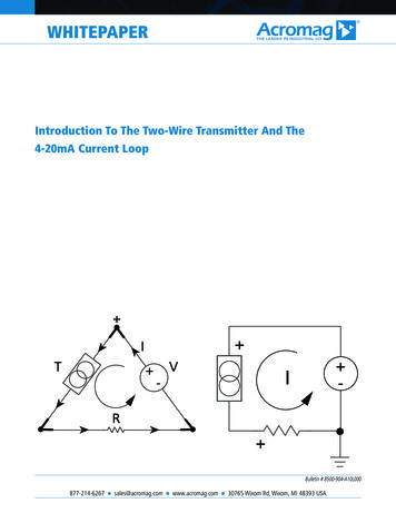
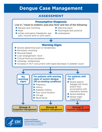
Transcription
Installation InstructionsPressure Transmitter Unit PTU 025VLT HVAC Drive FC 102Items SuppliedSee Illustration 1.1 for the list of supplied items.1M25 nut5Pressure Transmitter Unit PTU 0252M25 ground washer connection6Tube relief plate3M25 star washer7Interface cable for the C-option port4M25 gasket8Cable bindersTable 1.1Illustration 1.1 Pressure Transmitter Unit PTU 025 and Items SuppliedDanfoss A/S 12/2017 All rights reserved.MI08A102
Pressure Transmitter Unit PTU 025VLT HVAC Drive FC 102Installation InstructionsNOTICETo order the unit, use the following ordering number:ModelOrdering numberPTU 025, 4 inputs134B5925The PTU 025 unit can be installed in IP55 and IP66enclosures, and can be connected with the frequencyconverter using the C-option interface. This instruction isapplicable for a frequency converter in a standard configuration without any modifications.Table 1.2 Ordering NumbersSafety InstructionsFor important information about safety precautions for installation, refer to the product-specific operating guide.WARNINGDISCHARGE TIMEThe frequency converter contains DC-link capacitors, which can remain charged even when the frequency converter is notpowered. High voltage can be present even when the warning LED indicator lights are off. Failure to wait the specified timeafter power has been removed before performing service or repair work can result in death or serious injury. Stop the motor. Disconnect or lock PM motor.Disconnect AC mains and remote DC-link power supplies, including battery back-ups, UPS, and DC-link connections toother frequency converters.Wait for the capacitors to discharge fully. The minimum duration of waiting time is specified in Table 1.3.Before performing any service or repair work, use an appropriate voltage measuring device to make sure that thecapacitors are fully discharged.Voltage [V]200–240Minimum waiting time (minutes)47152030401.1–3.7 kW–5.5–45 kW–––––(1.50–5 hp)380–4801.1–7.5 kW(7.5–60 hp)–11–90 kW(1.50–10 hp)400–(15–121 hp)––315–1000 kW(450–1350 hp)90–315 kW––110–355 kW(150–500 hp)––75–315 kW–––––90–315 kW––400–1400 kW–(121–450 hp)500–––525–––(100–450 hp)525–6001.1–7.5 kW–11–90 kW(1.50–10 hp)690–(15–121 hp)––(100– 350 hp)525–690–1.1–7.5 kW11–90 kW(1.50–10 hp)(15–121 hp)–(500–1550 hp)450–1400 kW(600–1550 hp)Table 1.3 Discharge Time, VLT HVAC Drive FC 1022Danfoss A/S 12/2017 All rights reserved.MI08A102
Installation InstructionsPressure Transmitter Unit PTU 025VLT HVAC Drive FC 102Mechanical installationPrepare the hole for the installationThe options to mount the PTU 025 unit on an IP55/66enclosure include the following: Factory-installed M25 tread. Using the knock-out plate.Making a new hole in the connection plate. Holediameter: 25 mm (0.98 in).Illustration 1.3 The Nut, The Ground Connection, The Washer, TheGasketIllustration 1.2 PTU 025 Installation HoleFor grounding purpose, ensure that there is a good electricalconnection between the PTU 025 mounting star washer andthe enclosure.Installing the UnitTo install PTU 025:1.Place the gasket between the PTU 025 unit and theenclosure. This is necessary for the IP55/66 rating.2.Inside the enclosure, place the star washer, theground connection, and the nut. See Illustration 1.3.3.Put the ground wire inside the enclosure through thestar washer, the ground connection, and the nut.4.Rotate the unit to the required position. The unit canbe rotated 360 .5.MI08A102Illustration 1.4 Positioning the UnitFasten the nut with the momentum 5 Nm. The unitcannot be rotated after fastening the nut. SeeIllustration 1.4.Danfoss A/S 12/2017 All rights reserved.3
Installation InstructionsPressure Transmitter Unit PTU 025VLT HVAC Drive FC 102Electrical Installation1.Connect the PTU 025 unit to the C-option port.Ensure that the connectors are secure in sockets onboth ends and secure the cable inside the enclosurewith cable binders. See Illustration 1.5.2.Wire the outputs for the related signals and statuses.3.Mount the front cover of the frequency converter.4.Power up the frequency converter. Ensure that thefrequency converter identifies the PTU 025 unit.Illustration 1.5 PTU 025 Electrical Connection to the C-option Port4Danfoss A/S 12/2017 All rights reserved.MI08A102
Installation InstructionsPressure Transmitter Unit PTU 025VLT HVAC Drive FC 102Pressure Signals on OutputsThe frequency converter can be configured to transmit the pressure values on analog output or active status on digital and relayoutputs. Perform the configuration in parameter group 5-** Main Menu - Digital In/Out and parameter group 6-** Main Menu - AnalogIn/Out. See the wiring diagram in Illustration 1.6.Illustration 1.6 Wiring DiagramMI08A102Danfoss A/S 12/2017 All rights reserved.5
Installation InstructionsPressure Transmitter Unit PTU 025VLT HVAC Drive FC 102Mounting the Pressure TubesPTU 025 has 5 mm (0.2 in) tube connection taps. Attach high-pressure input tubes to the taps labeled H , and the low-pressuretubes on the L - taps. To prevent clogging of sensors, attach tubes to all connection taps. See Illustration 1.7.Illustration 1.7 Mounting Pressure TubesNOTICEPut a tube connection on all pressure transmitter taps to minimize the amount of dirt entering the unit. The minimum tubelength is 80 mm (3.1 in). If a sensor uses the surrounding pressure level, cut the tube at a place farther than the tube reliefplate.6Danfoss A/S 12/2017 All rights reserved.MI08A102
Installation InstructionsPressure Transmitter Unit PTU 025VLT HVAC Drive FC 102Parameter Configuration31-** Pressure Sensor OptionAfter PTU 025 is installed, power up the frequency converter.The LCP shows alarm A80, Drive initialized, which indicates thatthe frequency converter detected the new device. Press [Reset]to reset the alarm.Parameters related to the PTU 025 option.31-2* ConfigurationEach pressure-related status has its own below-level andabove-level trigger thresholds. The thresholds can be activatedindividually. When the actual pressure level exceeds thethreshold level, the frequency converter waits for the value inparameter 31-23 On Delay Time, and then performs a statuschange of a status. When the actual pressure goes below thethreshold level, the value in parameter 31-24 Reset Delay Timedefines when the status is reset. The value inparameter 31-25 Pressure filter time constant adjusts thedynamic of the reaction to the actual pressure input, to ensurereliable and stable status generation.31-20 Pressure/Speed CurveSelect the type of the pressure/speed curve.Illustration 1.8 Alarm A80, Drive InitializedEach pressure sensor can have a different setting.For options [1] Linear and [2] Square root, the pressure thresholdUse the LCP or MCT 10 Set-up Software to configure PTU 025.The PTU 025 option can be configured for the followingpurposes: Monitoring of the pressure transmitter signals. Showing the readouts on the LCP or transmittingthem via the fieldbus. Integration of the pressure monitoring into a systemsolution. PID closed-loop control based on airflow or pressurelevels.Signals from all PTU 025 sensors are active all the time andthe frequency converter can show the values on the LCPcontinuously. Use parameters in parameter group 31-2*Readouts to monitor filters, airflow, and pressure levels on theLCP or configure warnings or alarms. Values in parametergroup 31-2* Readouts are also available via the fieldbus.at 0 speed equals 10% of the value entered inparameter 31-21 Below level threshold or parameter 31-22 Abovelevel threshold.See Illustration 1.9.Illustration 1.9 Pressure/Speed DependencyOption:[0] *MCT 10 Set-up Software and the frequency converter checkwhether the entered pressure values are within the operatingranges of sensors. The LCP shows a warning if the enteredpressure value is outside the operating range.Use parameter 31-30 Press Sens Cmp State in the smart logiccontrol to achieve application-specific functionality. Useparameters in parameter group 13-9* User-defined Alerts andReadouts to configure application-specific messages, warnings,and alarms. For more information, see the programming guide.Function:Nonedepend on speed.[1]LinearThe pressure threshold isproportional to the speed.[2]Square rootThe pressure thresholddepends on the speed.The dependency isquadratic.31-21 Below level thresholdRange:#*MI08A102The pressure threshold isconstant and does not[ -2500 - 2500 Pa]Danfoss A/S 12/2017 All rights reserved.Function:Enter the below-level threshold.7
Pressure Transmitter Unit PTU 025VLT HVAC Drive FC 102Installation Instructions31-22 Above level thresholdRange:#*31-27 Pressure Sensor 2Function:[ -2500 - 2500 Pa]Range:Enter the above-level threshold.Function:[-500 - 500 Pa] Shows the readout of pressure sensor 2.31-28 Pressure Sensor 331-23 On Delay TimeRange:60 s*0 Pa*Range:Function:[0 - 3600 s]Enter the on delay time.0 Pa*Function:[-1000 - 1000 Pa] Shows the readout of pressure sensor3.31-24 Reset Delay TimeRange:9999 s*31-29 Pressure Sensor 4Function:[0 - 9999 s]Enter the reset delay time.Range:0 Pa*Function:[-2500 - 2500 Pa] Shows the readout of pressure sensor4.31-25 Pressure filter time constantRange:1 s*Function:31-30 Press Sens Cmp State[0.01 - 60 s] Enter the pressure filter time constant. Alonger value make the pressure signal morestable but less dynamic. A shorter valueRange:0*[0 255]Function:Shows the pressure sensor state. The state is an 8digit binary value, where 1 indicates an active statusallows to eliminate signal spikes and keepand 0 indicates an inactive status. Reading fromcontrol more dynamic.right to left, the first 4 digits indicate the alarms forthe below-level threshold, and the last 4 digits thealarms for the above-level threshold. For instance,31-2* Readoutscounting from right to left, sensor 1 for the belowlevel threshold is at position 1, and sensor 1 for theParameters in this group contain the actual pressure levels andthe status information. The LCP can be configured to show thevalues of these parameters in different display lines. Thetoggle function allows to show multiple pressure signals in thesame LCP line. The number is followed by the hash sign (#).See Illustration 1.9.above-level threshold is at position 5. SeeIllustration 1.9.NOTICEWhen using this parameter in the smart logiccontroller, the output status signal for thebelow-level threshold and for the above-levelthreshold is the same for a specific sensor.For example, in the following cases theoutput status signal is the same:Use parameter 0-20 Display Line 1.1 Small toparameter 0-24 Display Line 3 Large to configure the LCP toshow different pressure values. The below-level threshold for sensor1 is active. The above-level threshold for sensor1 is active.31-31 Press Sens toggleRange:Function:[0 - 4] Shows the pressure values on all sensors. Thereadout switches between sensors in a loop, goingfrom sensor 1 to sensor 4. The sensor number isfollowed by a hash sign, see Illustration 1.9.Illustration 1.9 Pressure Sensor Data on the LCP31-26 Pressure Sensor 1Range:0 Pa*8Function:[-500 - 500 Pa] Shows the readout of pressure sensor 1.Danfoss A/S 12/2017 All rights reserved.MI08A102
Installation InstructionsPressure Transmitter Unit PTU 025VLT HVAC Drive FC 102Application IntegrationPTU 025 is designed for central air handling units with 1 or more filters in the inlet/outlet part and with fan control based on theairflow or pressure level in the ventilation system. Separate frequency converters with separate pressure transmitter units controlthe inlet and outlet. PTU 025 has 4 pressure inputs. See the pressure ranges in Table 1.4. Sensors 3 and 4 can be configured foreither filter monitoring or PID control of the airflow or the pressure level.Illustration 1.10 Application Integration Example#RangeTypical function10–500 PaFilter monitoring20–500 PaFilter monitoring30–1000 PaFilter monitoring or PID control of the airflow or the pressure level40–2500 PaFilter monitoring or PID control of the airflow or the pressure levelTable 1.4 PTU 025 Sensors and their FunctionsIntegrating pressure signals into a system solutionThe pressure values can be read as analog values on theanalog output or as pulses on digital outputs. Useparameter 5-30 Terminal 27 Digital Output,parameter 5-31 Terminal 29 Digital Output, andparameter 5-40 Function Relay to send the sensor status to therelay or digital outputs. For more information about using thepressure values in applications and in the smart logic control,see the programming guide.MI08A102PID closed-loop control based on the airflow or pressurelevelUse parameters in parameter group 20-0* Feedback to use thepressure values for the frequency converter’s closed-loop PIDcontroller.Use parameters in parameter group 22-** Application Functionsto configure the monitoring of HVAC applications based onairflow. For more information, see the operating guide and theprogramming guide.Danfoss A/S 12/2017 All rights reserved.9
Dimensional DrawingsIllustration 1.11 Dimensional DrawingsDanfoss can accept no responsibility for possible errors in catalogues, brochures and other printed material. Danfoss reserves the right to alter its products without notice. This also applies to products already onorder provided that such alterations can be made without subsequential changes being necessary in specifications already agreed. All trademarks in this material are property of the respective companies. Danfossand the Danfoss logotype are trademarks of Danfoss A/S. All rights reserved.Danfoss A/SUlsnaes 1DK-6300 8A102*12/2017
The unit can be rotated 360 . 5. Fasten the nut with the momentum 5 Nm. The unit cannot be rotated after fastening the nut. See Illustration 1.4. Illustration 1.3 The Nut, The Ground Connection, The Washer, The Gasket Illustration 1.4 Positioning the Unit Installation Instructions Pressure Transmitter Unit PTU 025 VLT HVAC Drive FC 102