Transcription
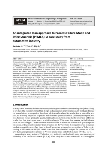
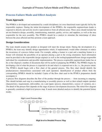
Example of Process Failure Mode and Effect AnalysisProcess Failure Mode and Effect AnalysisTeam Approach:The PFMEA is developed and maintained by a multi-disciplinary (or cross-functional) team typically led by theresponsible engineer. During the initial development of the PFMEA, the responsible engineer/team leader isexpected to directly and actively involve representatives from all affected areas. These areas should include butare not limited to design, assembly, manufacturing, materials, quality, service, and suppliers, as well as the arearesponsible for the next assembly. The PFMEA should be a catalyst to stimulate the interchange of ideasbetween the areas affected and thus promote a team approach.Design Consideration:High level to Detailed Process MapBy Pretesh Biswas (APB Consultant)Page1The team should assume the product as designed will meet the design intent. During the development of aPFMEA, the team may identify design opportunities which, if implemented, would either eliminate or reducethe occurrence of a process failure mode. For example, adding a feature to a part and a matching feature to afixture will eliminate the possibility of an operator placing a part in the wrong orientation. Such informationmust be provided to the responsible design engineer as well as the tooling/equipment/fixture design-responsibleindividual for consideration and possible implementation. The process-responsible engineer/team leader has athis or her disposal a number of documents that will be useful in preparing the PFMEA. The PFMEA begins bydeveloping a list of what the process is expected to do and what it is expected not to do, i.e., the process intent.The PFMEA should begin with a flow chart of the general process. This flow chart should identify theproduct/process characteristics associated with each operation. Identification of product effects from thecorresponding DFMEA should be included. Copies of the flow chart used in the PFMEA preparation shouldaccompany it.A process flow diagrams describes the flow of the product through the process — from incoming to outgoing.This should include each step in a manufacturing or assembly process as well as their related outputs (productcharacteristics, requirements, deliverables, etc.) and inputs (process characteristics, sources of variation, etc.).The detail of the process flow depends on the stage of process development discussion. The initial flow diagramis generally considered a high level process map. It needs more detailed analysis to identify the potential failuremodes.
Example of Process Failure Mode and Effect AnalysisThe PFMEA should be consistent with the information in the process flow diagram. The scope of the processflow diagram should include all manufacturing operations from processing of individual components toassemblies including shipping, receiving, transportation of material, storage, conveyors, labeling, etc. Apreliminary risk assessment using the process flow diagram may be performed to identify which of theseoperations or individual steps can have an impact on the product manufacturing and assembly and should beincluded in the PFMEA.The PFMEA development continues by identifying the requirement(s) for each process/function. Requirementsare the outputs of each operation/step and relate to the requirements for the product. The Requirements providea description of what should be achieved at each operation/step. The Requirements provide the team with abasis to identify potential failure modes. In order to assure continuity, it is highly recommended that the samecross-functional team develop the Process Flow Diagram, PFMEA, and Control Plan.Other sources of information that are useful in providing the team with ways to focus and capture discussionson the requirements of the process include: DFMEADrawings and design recordsBill of ProcessInterrelationship (Characteristic) matrixInternal and external (customer) nonconformance (i.e., known failure modes based on historical data)Quality and Reliability HistoryAfter establishing the scope of the analysis effort, the team should begin by reviewing historical information.The areas to review should include: Lessons that have been learned from previous product and process design implementation, andAny information available that establishes best practices including items such as guidelines andstandards, standard part identification, or error-proofing methods.Page2Quality performance information available from similar, previous product and process designs, including itemssuch as process yield, first time capability (both end of line and at each operation), Pans per Million (PPM),process capability indices (Cpk and Ppk), and warranty metrics. The information can be useful input fordetermination of severity, occurrence and detection rankings.By Pretesh Biswas (APB Consultant)
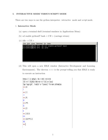
Example of Process Failure Mode and Effect AnalysisSample PFMEA Form with Minimal Information Elements & Example EntriesFMEA Number (A)Enter an alphanumeric string which is used to identify the FMEA document. This is used for document control.By Pretesh Biswas (APB Consultant)PageEnter the name and number of the system, subsystem, or component which is being analyzed.3System, Subsystem, or Component Name and Number (B).
Example of Process Failure Mode and Effect AnalysisProcess Responsibility (C)Enter the OEM, organization, and department or group who is Process design responsible. Also enter the supplyorganization name, if applicable.Model Year(s)/Program(s) (D)Enter the intended model year(s) and program(s) that will use or be affected by the Process being analyzed (ifknown).Key Date (E).Enter the initial PFMEA due date, which should not exceed the scheduled start of production date. In case of asupply organization, this date should not exceed the customer required Production Part Approval Process(PPAP) submission date.FMEA Dates (F)Enter the date the original PFMEA was completed and the latest revision date.Core Team (G)Enter the team members responsible for developing the PFMEA. Contact information (e.g., name, organization,telephone number, and email) may be included in a referenced supplemental document.Prepared By (H)Enter the name and contact information including the organization (company) of the engineer responsible forpreparing the PFMEA.Body of DFMEA Form (Fields a-n)The body of the PFMEA contains the analysis of risks related to the potential failures, and improvement actionbeing taken.Process steps / Process Function /Requirements (a)Process Step/Function can be separated into two (or more) columns or combined into a single, bridged columnwhich encompasses these elements. Process Steps may be listed in the Process Step/Function column oradditional column(s) may be added containing the functions or requirements of that process step. “ProcessStep”, “Function”, and “Requirements” are described below:Process Step (a1)Page4Enter the identification of the process step or operation being analyzed, based on the numbering process andterminology. For example, enter the number and identifier (e.g., name). Process numbering scheme, sequencing, andterminology used should be consistent with those used in the process flow diagram to ensure traceability andrelationships to other documents (Control Plans, operator instructions, etc). Repair and rework operations should alsobe included.By Pretesh Biswas (APB Consultant)
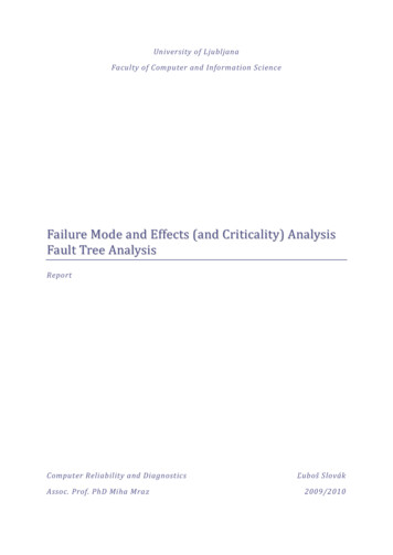
Example of Process Failure Mode and Effect AnalysisProcess Function (a1)List the process function that corresponds to each process step or operation being analyzed. The processfunction describes the purpose or intent of the operation. A risk analysis is recommended in order to limit thenumber of steps to be included to only those that add value or otherwise are seen as likely to have a negativeimpact on the product. If there are multiple process functions being analyzed with respect to a given operation,each should be aligned on the form with its respective “Requirements” to aid in the development of theassociated failure modes. Process Function becomes a2 if Process Step and Process Function are split.Requirements (a2)List the requirements for each process function of the process step or operation being analyzed. Requirementsare the inputs to the process specified to meet design intent and other customer requirements. If there aremultiple requirements with respect to a given function, each should be aligned on the form with the respectiveassociated failure modes in order to facilitate the analysis.Potential Failure Mode (b)Potential failure mode is defined as the manner in which the process could potentially fail to meet the processrequirements (including the design intent). In preparing the FMEA, assume that the incoming part(s)/material(s)are correct. Exceptions can be made by the FMEA team where historical data indicate deficiencies in incomingpart quality. The team should also assume that the basic design of the product is correct; however, if there aredesign issues which result in process concerns, those issues should be communicated to the design team forresolution. List the potential failure mode(s) for the particular operation in terms of the process requirement(s)(e.g., as documented in the process flow diagram.) Assume that the failure could occur but may not necessarilyoccur. Potential failure modes should be described in technical terms, not as a symptom noticeable by thecustomer. If the requirements have been well defined, then the potential failure mode is readily identifiable bydetermining the condition when a specific requirement is not met. Each requirement may have multiple failuremodes. A large number of failure modes identified for a single requirement usually indicates that therequirement is not well defined. The assumption is made that the failure could occur but may not necessarilyoccur - consequently the use of the word “potential”. Verification of completeness of the potential failure modescan be made through a review of past things-gone-wrong, concerns, reject or scrap reports, and groupbrainstorming. Sources for this should also include a comparison of similar processes and a review of customer(End User and subsequent operation) claims relating to similar components.Process step/functionAttach seat cushion totrack using a torque gunRequirementFour ScrewsSpecified ScrewsAssembly Sequence: First screw in the RightFront holeScrew fully seatedPotential failure ModeFewer than four screwsWrong screw usedScrew placed in any other holePage5Screw not fully seatedScrew torque too highScrew torqued to dynamic torque specificationScrew torque too lowExample of Process step/function, Requirement & Potential failure mode ColumnBy Pretesh Biswas (APB Consultant)
Example of Process Failure Mode and Effect AnalysisPotential Effect(s) of Failure (c)Potential effects of failure are defined as the effects of the failure mode as perceived by the customer(s). Theeffects of the failure should be described in terms of what the customer might notice or experience,remembering that the customer may be an internal customer as well as the ultimate End User. The customer(s)in this context could be the next operation, subsequent operations or locations, the dealer, and/or the vehicleowner. Each must be considered when assessing the potential effect of a failure. The product effects in thePFMEA should be consistent with those in the corresponding DFMEA. If the failure mode could impact safetyor cause noncompliance to regulations, this should be clearly identified in the PFMEA. For the End User, theeffects should be stated in terms of product or system performance. If the customer is the next operation orsubsequent operation(s) / location(s), the effects should be stated in terms of process / operation performance.RequirementFour ScrewSpecified ScrewAssembly sequence:First screw in right front holeScrew fully seatedScrew torqued to dynamic torquespecificationFailure ModeEffectEnd user: Loose seat cushion and noise.Manufacturing andFewer than four screwAssembly: Stop shipment and additional sort andrework due to affected portion.Manufacturing and Assembly: Unable to installWrong screw usedscrew in station.Screw placed in anyManufacturing and assembly: Difficult to installother holeremaining screws in station.End User: Loose seat cushion and noise.Screw not fully seated Manufacturing and Assembly: Sort and reworkdue to affected portion.End User: Loose seat cushion due to subsequentfracture of screw and noise.Screw torque too highManufacturing and Assembly: Sort and reworkdue to affected portion.End User: Loose seat cushion due to gradualloosening of screw and noise.Screw torque too lowManufacturing and Assembly: Sort and reworkdue to affected portion.Example of EffectsSeverity (d):Page6Severity is the value associated with the most serious effect for a given failure mode. Severity is a relativeranking within the scope of the individual FMEA. The team should agree on evaluation criteria and a rankingsystem and apply them consistently, even if modified for individual process analysis. It is not recommended tomodify criteria ranking values of 9 and10. Failure modes with a rank of severity 1 should not be analyzedfurther.By Pretesh Biswas (APB Consultant)
Example of Process Failure Mode and Effect AnalysisEffectFailure to MeetSafety and/orRegulatoryRequirementsMajor inor DisruptionCriteriaSeverity of Effect on Product (Manufacturing Effect)May endanger operator (machine or assembly) without warning.May endanger operator (machine or assembly) with warning.100% of product may have to be scrapped. Line shutdown or stop ship.A portion of the production run may have to be scrapped. Deviation from primaryprocess including decreased line speed or added manpower.100% of production run may have to be reworked off line and accepted.A portion of the production run may have to be reworked off line and accepted.100% o
Sample PFMEA Form with Minimal Information Elements & Example Entries FMEA Number (A) Enter an alphanumeric string which is used to identify the FMEA document. This is used for document control. System, Subsystem, or Component Name and Number (B). Enter the name and number of the system, subsystem, or component which is being analyzed. Example of Process Failure Mode and Effect File Size: 748KBPage Count: 13