Transcription
Buildings 2013, 3, 506-531; doi:10.3390/buildings3030506OPEN ACCESSbuildingsISSN truction Delay Analysis Techniques—A Review ofApplication Issues and Improvement NeedsNuhu BraimahCivil Engineering Department, School of Engineering and Design, Brunel University,Uxbridge, Middlesex UB8 3PH, UK; E-Mail: nuhu.braimah@brunel.ac.uk;Tel.: 44-0-1895-265-919; Fax: 44-0-1895-269-782Received: 8 May 2013; in revised form: 1 July 2013 / Accepted: 18 July 2013 /Published: 23 July 2013Abstract: The time for performance of a project is usually of the essence to the employerand the contractor. This has made it quite imperative for contracting parties to analyseproject delays for purposes of making right decisions on potential time and/or costcompensation claims. Over the years, existing delay analysis techniques (DATs) for aidingthis decision-making have been helpful but have not succeeded in curbing the highincidence of disputes associated with delay claims resolutions. A major source of thedisputes lies with the limitations and capabilities of the techniques in their practical use.Developing a good knowledge of these aspects of the techniques is of paramountimportance in understanding the real problematic issues involved and their improvementneeds. This paper seeks to develop such knowledge and understanding (as part of a widerresearch work) via: an evaluation of the most common DATs based on a case study, areview of the key relevant issues often not addressed by the techniques, and the necessaryimprovements needs. The evaluation confirmed that the various techniques yield differentanalysis results for the same delay claims scenario, mainly due to their unique applicationprocedures. The issues that are often ignored in the analysis but would also affect delayanalysis results are: functionality of the programming software employed for the analysis,resource loading and levelling requirements, resolving concurrent delays, and delay-pacingstrategy. Improvement needs by way of incorporating these issues in the analysis andfocusing on them in future research work are the key recommendations of the study.Keywords: delay analysis; construction claims; extension of time; scheduling; damages
Buildings 2013, 35071. IntroductionThe duration of contract performance has a direct effect on the profitability of construction projectsfrom the perspective of all stakeholders [1,2]. For project owners, lost profits or benefits stem frombeing unable to make use of the project at the agreed date whilst to the contractor, extra cost will beincurred due to prolonged stay on site. Most standard forms of contract thus have provisions thatanticipate delay brought about by the actions and/or inactions of the contractor, the owner or areoutside the control of both parties. The contractor is often excused from the consequences and/orallowed compensation for any costs due to delays resulting from events or circumstances that arebeyond its control. Contractual provisions also allow the owner to recover liquidated damages from thecontractor for failure to deliver the project within the contract performance period. Liquidated damagesclauses entitle the owner to recovery of a specified sum of money for each day or week of culpabledelay. In both instances, a detailed schedule analysis is required to investigate the events that haveactually caused the project to overrun. Over the years, owners and contractors have used various DelayAnalysis Techniques (DATs) to achieve this. However, in the vast majority of cases, the parties are notable to settle delay claims amicably resulting in costly disputes after project completion [3–5].Consequently, delay claims are now a major source of conflict in the construction industry and alsoone of the most difficult to resolve [6–8]. This has generated considerable initiatives from researchersand industry practitioners aimed at enhancing the application of existing DATs (see for example, [6,9–15])and the development of “good practice” documents for providing guidance to practitioners on what thebest application of the various techniques entails and the circumstances that dictate their proper use. Ofsuch documents, the most notable are the “Delay and Disruption Protocol” [7] developed by the UK’sSociety of Construction Law and “Recommended Practice on Forensic Schedule Analysis” by theAssociation for Advancement of Cost Engineering International [16] of the USA.In spite of the many contributions, proper analysis of delay claims which take into consideration theeffect of a number of scheduling and delay issues is often lacking in practice [8,14,17]. Therefore, theneed for greater awareness and incorporation of these issues in delay analysis is crucial to ensuringfairness and amicable resolution of delay claims. As part of a wider study aimed at addressing theseissues, the purpose of this paper is to: discuss the most common existing DATs, as well as review theissues that are often missed in the analysis, and the required improvement needs. The scope of thiswider study involves investigating the techniques’ applications (in theory and in practice) thoroughlywith the view to developing an appropriate framework for enhancing their proper usage, in order tohelp reduce the frequent delay claims resolution difficulties. This paper’s presentation on DATs, asdetailed in the next section, was done based on a hypothetical case study so as to clearly demonstratethe application processes of the techniques and their weaknesses in presenting (or defending)delay claims.2. Existing Delay Analysis TechniquesThe objective of delay analysis is to calculate the project delay and work backwards to try toidentify how much of it is attributable to each party (contractor, owner, or neither) so that time and/orcost compensation can be decided. Questions that need to be answered here often include [3,18]:
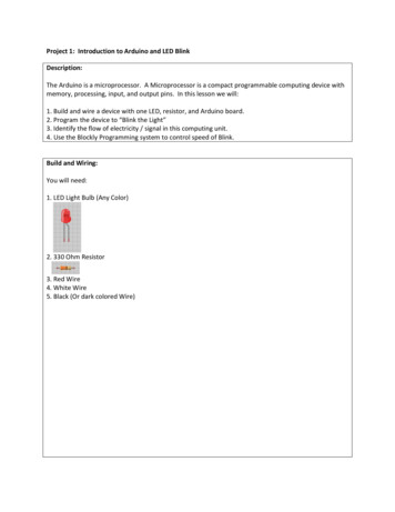
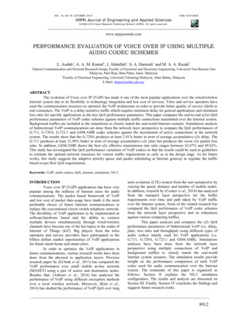
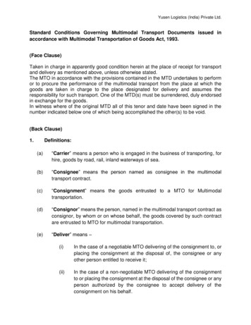
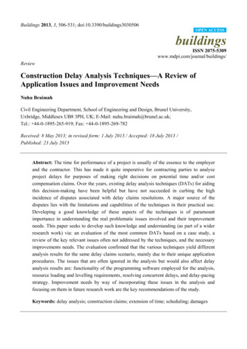
Buildings 2013, 3 508what was supposed to happen?what did actually happen?what were the variances?how did they affect the project schedule?The various DATs have varying capabilities in providing sound answers to these questions. Thetechniques can be grouped under non-Critical Path Method (CPM)-based techniques and CPM-basedtechniques. They have been reported by different authors in the literature using different names, with themost common techniques being: “as-planned vs. As-built”, “impacted as-planned”, “as-planned but for”,“collapsed as-built”, “window analysis”, and “time impact analysis” (see, for example, [5–8,19–24]).3. A Case Study ProjectTo critically evaluate the existing techniques, a simple case study has been designed andsimulated with various delay scenarios. The case study project involves the construction of a smallgarage with the necessary approach drive-in, as shown in the network diagram of Figure 1, adoptedfrom Pilcher [25].Figure 1. Arrow diagram of the case-study project.The as-planned programme of this project (in bar chart format for clarity) is as shown in Figure 2,indicating a total project duration of 40 days. The as-planned critical path, indicated in red bars, flowsthrough activities of the garage structure, with a 5-day float on the path of drive-in activities.The project started as scheduled but progress was affected by three main types of delay events:(1) Events for which the contractor assumes the risks of costs and the time consequences involved,which are often categorised as “Nonexcusable–Noncompensable” delays (NN); (2) events for whichthe contractor is entitled to both time extensions and recovery of extra cost consequential upon thedelay [“Excusable Compensable” delays (EC)]; and finally, (3) those events for which no party hascontrol over or bears the risks involved, (e.g., acts of God and strikes), which are often termed as“Excusable Non-compensable” (EN) delays.
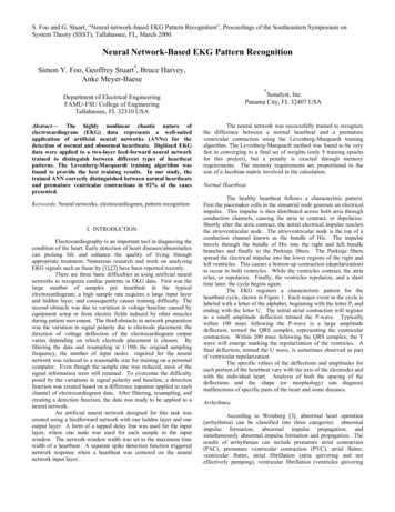
Buildings 2013, 3509Figure 2. As-planned schedule.Act.IDO riginaldurationActivity D escriptionD ays51015202530354045G ARAG EG1Excavate foundation5G2C oncrete foundation3G3B rickw ork to 1m high6G4B rickw ork to roof level14G5C oncrete to floor slab4G6Fix roof structure6G7W aterproof roof2G8Fix doors2G9Paint and clean up4C om pletiondateDRIVE-IND1C lear and excavate for drive -in15D2H ardcore base to drive10D3Tarm acadam to drive -in5Table 1 below defines the delay scenarios encountered in the hypothetical project. The as-builtschedule, which includes all delays that occurred during construction of the project, had total projectduration of 51 days and a critical path along the drive-in activities (see Figure 3). To distinguishbetween the various delays, EC delays are indicated in dark horizontal strips and NN delays in darkdiagonal strips. Apart from the delays, there were also changes in the planned sequence between someof the activities. The as-built programme thus shows start–start logic with lag of 2 days between thefirst two activities of the garage instead of the originally planned finish–start relationship. Similar logicwith a lag of 3 days exists between the first two activities of the drive-in.Figure 3. As-built schedule.Act.IDActivity 6065GARAGEG1Excavate foundation5G2Concrete foundation6G3Brickwork to 1m high6G4Brickwork to roof level17G5Concrete to floor slab5G6Fix roof structure6G7Waterproof roof5G8Fix doors5G9Paint and clean up4DRIVE-IND1Clear and excavate for drive-in22D2Hardcore base to drive19D3Tarmacadam to drive-in9Actual completiondate70
Buildings 2013, 3510Table 1. Delays events that affected the sample project.As planneddurationChronologyof delays31152Brickwork toroof level (G4)143Concrete tofloor slab (G5)44Hardcore baseto drive-in (D2)105Brickwork toroof level (G4)146Hardcore baseto drive-in (D2)107Tarmacadam todrive-in (D3)58Waterproof roof (G7) 29Fix doors (G8)10ActivityConcretefoundations (G2)Clear and excavatefor drive-in (D1)2Delay informationDescriptionContractor had a labour problemso it took 3 days extra to complete activity G2.Contractor encountered unforeseen adverse groundcondition during excavation of the drive-in.Activity G4 did not start immediatelyafter completion of its predecessor as-planneddue to 1-day delay by the contractor’s brick supplier.Contractor advised the owner on theneed to increase the thickness of the floor slab. Thischange required 1 extra day to accomplish.After 5 days of working on activity D2, the ownersuspended works for 3 days as a decision on the suitabilityof the hardcore material was being made.The owner ordered the contractor toadd an extra window after the completion of G4.This design change caused 2-day delay.A quality control test revealed that certain sections of thedrive-in base were poorly constructed. This defectivework resulted in 5 days of rework by the contractor.There was a 4-day delay by the ownerin making available to the contractor anowner-furnished equipment for activity D3It took the contractor 3 more days to complete activity G6.The owner changed his mind on the type of doorused for the garage so ordered the contractor to makechanges. This caused 3 extra days of work.TypeStart date(day)End C24284EC30322NN31365EC38424NN40433EC40433
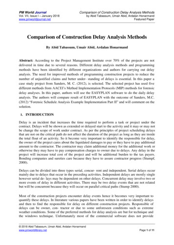
Buildings 2013, 35114. Project Delay Analysis Using the Various Techniques4.1. As-Planned vs. As-BuiltUnder this method, all delaying events (EC, EN and NN delays) encountered on the project aredepicted on the as-built schedule. The difference between the as-planned and as-built completion datesis the amount of time for which the claimant will request for compensation. The critical path isdetermined once in the as-planned and again in the as-built schedule [8,22]. This technique and the netimpact technique utilising bar chart are similar in that they all show the net effect of all claimed delays.By the approach of Stumpf [24], the following illustrates the allocation of delay responsibility betweenthe owner and the contractor for the sample project.Sum of contractor-caused delays (NN) ΣNNi 3 1 5 3 12 days (see Table 1);Sum of owner-caused delays (EC) ΣECi 7 1 4 2 4 3 21 days (see Table 1).From the above, the assumption is that concurrent delay due to both parties is 12 days (“i.e.”, thelower of the above two types of delays). Therefore, net project delays for which the owner isresponsible 21 12 9 days;From Figures 2 and 4, the net total project delay 51 40 11 days, the balance is the contractorresponsibility, which is 11 9 2 days. The limitations of this methodology are: it does not scrutinize delay types and this makes it easy for it to be manipulated and distortedto reflect either the position of the claimant or the defendant;it ignores the dynamic nature of the critical path and any changes in schedulelogic [20,24,26];no attempt is made to determine the individual impact of each delay on the projectcompletion. All delays, including delays on non-critical path, were summed up and their neteffect calculated.Figure 4. As-built schedule with delays.Act.Activity 20253035404550556065GARAGEG1Excavate foundation5G2Concrete foundation33G3Brickwork to 1m high60G4Brickwork to rooflevel143G5Concrete to floor slab41G6Fix roof structure60G7Waterproof roof23G8Fix doors23G9Paint and clean up40157109540D2D3Clear and excavatefor drive-inHardcore base todriveTarmacadam todrive-inNN 1EC 2NN 3EC 1EC 3EC 7DRIVE-IND1NN 3NN 5EC 4EC 4Actual completiondate70
Buildings 2013, 35124.2. Impacted As-PlannedThis method measures the impact of the delays on the contractor’s as-planned CPM schedule. Thevarious delays are formulated as activities and added to the as-planned network in a chronologicalorder showing the effect of each delay at a time and demonstrating how the project is beingdelayed [27]. The amount of delay equals the difference in completion dates between the schedulesbefore and after the impacts. The technique can be used for analysis of delay during and afterproject completion.Delay analysis of the sample project using this technique was carried out by sequential addition ofthe delays to the as-planned schedule. The impact of each delay is as shown in Figures 5–13 below.Figure 5. Impact of first delay.Act.Activity 202530354045GARAGEG1Excavate foundation5G2Concrete foundation3G3Brickwork to 1m high6G4Brickwork to rooflevel14G5Concrete to floor slab4G6Fix roof structure6G7Waterproof roof2G8Fix doors2G9Paint and clean up4As-plannedcompletion3Delay 3daysDRIVE-IND1D2D3Clear and excavatefor drive-inHardcore base todriveTarmacadam todrive-in15105Figure 6. Impact of second delay.Act.Activity 2025303540455055GARAGEG1Excavate foundation5G2Concrete foundation3G3Brickwork to 1m high6G4Brickwork to rooflevel14G5Concrete to floor slab4G6Fix roof structure6G7Waterproof roof2G8Fix doors2G9Paint and clean up43delay 0(completion date same asprevious schedule)DRIVE-IND1D2D3Clear and excavatefor drive-inHardcore base todriveTarmacadam todrive-in15105760
Buildings 2013, 3513Figure 7. Impact of third delay.Act.Activity 202530354045505560GARAGEG1Excavate foundation5G2Concrete foundation3G3Brickwork to 1m high6G4Brickwork to rooflevel14G5Concrete to floor slab4G6Fix roof structure6G7Waterproof roof2G8Fix doors2G9Paint and clean up4Previouscompletion date31Delay 1dayNew completion dateDRIVE-IND1D2D3Clear and excavatefor drive-inHardcore base todriveTarmacadam todrive-in157105Figure 8. Impact of fourth delay.Act.Activity DescriptionIDPlanned Delayduration durationDays510152025303540455055GARAGEG1Excavate foundation5G2Concrete foundation3G36141G5Brickwork to 1m highBrickwork to rooflevelConcrete to floor slab41G6Fix roof structure6G7Waterproof roof2G8Fix doors2G9Paint and clean up4G43Delay 0DRIVE-IND1D2D3Clear and excavatefor drive-inHardcore base todriveTarmacadam todrive-in15105Completion date same asprevious schedule760
Buildings 2013, 3514Figure 9. Impact of fifth delay.Act.Activity 202530354045505560GARAGEG1Excavate foundation5G2Concrete foundation3G36141G5Brickwork to 1m highBrickwork to rooflevelConcrete to floor slab41G6Fix roof structure6G7Waterproof roof2G8Fix doors2G9Paint and clean up4G4previouscompletion date3Delay 1 dayNew completiondateDRIVE-IND1D2D3Clear and excavatefor drive-inHardcore base todriveTarmacadam todrive-in1571045Figure 10. Impact of sixth delay.Act.Activity DescriptionIDPlanned Delayduration durationDays510152025303540455055GARAGEG1Excavate foundation5G2Concrete foundation3G36141 2G5Brickwork to 1m highBrickwork to rooflevelConcrete to floor slab41G6Fix roof structure6G7Waterproof roof2G8Fix doors2G9Paint and clean up4G43Delay 1 dayNew completiondateDRIVE-IND1D2D3Clear and excavatefor drive-inHardcore base todriveTarmacadam todrive-in1571045previouscompletion date60
Buildings 2013, 3515Figure 11. Impact of seventh delay.Act.Activity 202530354045505560GARAGEG1Excavate foundation5G2Concrete foundation3G36141 2G5Brickwork to 1m highBrickwork to rooflevelConcrete to floor slab41G6Fix roof structure6G7Waterproof roof2G8Fix doors2G9Paint and clean up4G4previouscompletion date3Delay 4 daysNew completiondateDRIVE-IND1D2D3Clear and excavatefor drive-inHardcore base todriveTarmacadam todrive-in157104 55Figure 12. Impact of eighth delay.Act.Activity 202530354045505560GARAGEG1Excavate foundation5G2Concrete foundation3G36141 2G5Brickwork to 1m highBrickwork to rooflevelConcrete to floor slab41G6Fix roof structure6G7Waterproof roof2G8Fix doors2G9Paint and clean up4G43D2D3Clear and excavatefor drive-inHardcore base todriveTarmacadam todrive-inDelay 4 daysNewCompletiondateDRIVE-IND1previouscompletion date157104 554
Buildings 2013, 3516Figure 13. Impact of ninth and tenth delays.The first delay (NN 3) was on the critical path, G1-G2-G3-G4-G6-G7-G8-G9 so it caused 3 daysof slippage to the as-planned programme. The second, fourth, ninth and tenth delays were onnon-critical paths so their impacts did not cause any slippage. The impacts of fifth, seventh and eighthdelays caused project slippage on the critical path, D1-D2-D3-G9. A summary of the results obtainedare as shown in Table 2.Table 2. Impacted as-planned results.Chronology of delaysActivity123456789 and 10G2D1G4G5D2G4D2D3G7 and G8TypeNNECNNECECECNNECNN and ECDelayDuration (days)371142543 and 3Impact (days)301011440From Table 2, the owner is responsible for six days of delay to the project whilst the contractor isresponsible for 8 days. The sum of these delays is greater than the actual project delay of 11 delaysbecause of the failure of this technique to consider any changes in the as-planned programme, which isby maintaining the original finished–start relationship of all activities in the analyses.The limitations of this method include the following: it uses fixed as-planned schedule to analyse delays out of context and time [24,26];
Buildings 2013, 3 517the original baseline programme may not be a realistic model on which to base thewhole analysis;it has the potential of failing to consider the delays of all parties especially that of the claimant(“i.e.”, being one-sided);potential disputes over the adequacy of the as-planned schedule because it is not economicallypossible, nor does it makes sense, to schedule the entire project in detail at its inception [3].4.3. As-Planned But forThis method entails injecting the as-planned schedules with all the delays of a particular party toform an adjusted schedule. The completion date of this adjusted as-planned schedule compared withthe actual completion date gives the amount of delay for which the other party is responsible [8,19,22].A contractor using this method would identify and add all non-excusable delays to the as-plannedschedule, whereas the owner would add all excusable delays. The advantage of this method is thatit can be performed quickly because there is no need to consider actual progress of the work.This technique is applied to the sample project first for contractor’s point of view and then for owner’spoint of view.Contractor’s point of view: Under this, all the contractor-caused delays were impacted on theas-planned schedule. This resulted in an adjusted as-planned schedule with completion date as day 47and G1-G2-G3-G4-G6-G7-G8-G9 as the critical path (see Figure 14 below). With the actualcompletion date as day 51, the owner is responsible for 4 days’ project delay, which could be chargedas compensable delay. The amount of delay for which the contractor is responsible is 47 40 7 days,where 40 is the original as-planned completion date.Figure 14. As-planned schedule impacted with contractor’s delays.Owner’s point of view: Under this, all the owner-caused delays were impacted on theas-planned schedule. This resulted in an adjusted as-planned schedule with completion date as day 49
Buildings 2013, 3518and D1-D2-D3-G9 as the critical path (see Figure 15 below). With actual completion date as day 51,the contractor is responsible for 2 days’ project delay, which could be charged for liquidated damagesby the owner. The owner is then responsible for the difference between the adjusted schedule and theoriginal completion date, i.e., 49 40 9 days.Figure 15. As-planned schedule impacted with owner’s delays.The limitations of this method include the following: it does not take into account any changes in the critical path schedule during the courseof the project [19];it assumes that the planned construction sequence remains valid during the projectduration [5];owner’s point of view and contractor’s point of view may yield different results resulting indisputes (as this case shows).4.4. Collapsed As-BuiltIn principle, this method is a form of “but for” which does not use the as-planned as a baselineschedule, but rather uses the as-built schedule (and thus also referred to as “as-built but for” technique). Itinvolves removing the delays of each party from the as-built network so that the resulting schedule willgive the completion date of the project but for the delays of the other party [18,24]. Like the previoustechnique, this technique is applied to the sample project first for contractor’s point of view and thenfor owner’s point of view as follows:Contractor’s point of view: Under this, all owner-caused delays were subtracted from the as-builtschedule resulting in a collapsed as-built schedule of completion date as day 45 and critical pathG1-G2-G3-G4-G6-G7-G8-G9 (see Figure 16).
Buildings 2013, 3519Figure 16. As-built schedule with owner’s delays subtracted.With actual completion date as day 51, the owner is responsible for 6 days of the (51–45) projectdelay, which could be charged as compensable delay. Comparing the collapsed as-built schedule withthe original schedule gives 45 40 5 days project delay, as caused by the contractor.Owner’s point of view: Under this, all contractor-caused delays were subtracted from the as-builtschedule resulting in a collapsed as-built schedule of completion date as day 46 and critical pathD1-D2-D3-G9 (see Figure 17). With actual completion date as day 51, the contractor is responsible for5 days of project delay, which could be charged for liquidated damages. Comparing the collapsedas-built schedule with the original schedule gives 46 40 6 days project delay as that caused bythe owner.Figure 17. As-built schedule with contractor’s delays subtracted.This technique and the “as-planned but for” could give similar results if the planned logic remainsunchanged in the course of the project. The perceived advantage of this technique is that it is based onactual events on the project, making it one of the techniques of high credibility [5]. However, itsshortcomings include the following:
Buildings 2013, 3 520in collapsing the schedule, the analyst is typically forced to insert after-the-fact logic ties whichmay not reflect the thinking of the executor of the schedule during actual performance [5];the removal of the delays from the schedule could result in an unrealistic as-built but-forschedule, particularly when the schedule sequence has been so much impacted by those delays;adjusting the collapsed schedule to suit what the contractor is likely to follow requiresexperience and sound judgement beyond the capability of most analysts [18];it ignores the circumstances at the time of the delay and the dynamic nature of the critical path;the identification of the as-built critical path requires great deal of effort on judgement andschedule manipulation [20];the use of as-built information to prepare the as-built schedule is subjective and highlyamenable to manipulation [27].4.5. “Window” AnalysisThis technique involves interim assessment of delay on updated schedules at specific periods of theproject. This is similar to the “snapshot technique” described by Alkass [19] and “contemporaneousperiod analysis” described by Schumacher [2]. First, the total project duration is divided into a numbertime periods (windows or snapshots) usually based on major changes in planning or major projectmilestones [6,8]. The schedule within each window is updated to reflect the actual durations andsequence at the time of the delay while the remaining as-planned schedule beyond the window periodis maintained. Analyses are performed to determine the critical path and new completion date. Thisnew completion date is compared with the as-planned completion date prior to this analysis to give theamount of delay during that window period.Applying this technique to the sample project, the total contract period was first broken into discretetime periods at days 10, 21, 32, 40 and 51, resulting in 5 “window” periods. Analysis was carried outfor each “window” successively at the various updates as shown in Figures 18–22 below.Figure 18. Updated schedule on day 10.
Buildings 2013, 3521Figure 19. Updated schedule on day 21.Figure 20. Updated schedule on day 32.DelayAct.Planned DelayActivity DescriptionduratioIDduration durationnGARAGEG1Excavate foundation5G2Concrete foundation3G3Brickwork to 1m high6G4Brickwork to roof level141 2G5Concrete to floor slab41G6Fix roof structure6G7Waterproof roof2G8Fix doors2G9Paint and clean up4DRIVE-INClear and excavate forD1drive-inD2 Hardcore base to driveD3Tarmacadam to drive-in3351015202530Days3540455055completiondate at startof windowcompletion date157104 153rd Window606570
Buildings 2013, 3522Figure 21. Updated schedule on day 40.Figure 22. Updated schedule on day 51.Act.Act. Activity DescriptionActivity ration5th ate foundation5G2Concrete foundation3G3141 2G5Brickwork to 1m highBrickwork to rooflevelConcrete to floor slab41G6Fix roof structure6G7Waterproof roof23G8Fix doors23G9Paint and clean up4G433Completion date at startof window6completion dateDRIVE-IND1D2D3Clear and excavatefor drive-inHardcore base todriveTarmacadam todrive-in157104 554There was 1-day slippage at the end of the 1st window due to 3 days’ delay by the contractor on thecritical path G1-G2-G3-G4-G6-G7-G8-G9. The updated schedule at the end of the 2nd windowshowed 1 day slippage due to 1-day delay by the contractor on the critical path. There was 2 days ofproject delay at the end of the 3rd window as a result of 2 days delay by the owner on the critical path.The critical path changed to D1-D2-D3-G9 at the end of the 4th window, resulting in 5 days slippage.By “but for” analysis, the contractor’s delay responsibility within this window is 2 days while that ofthe owner is 3 days. At the end of the last window, further 2 days’ slippage was caused by the owneralong the critical path, D1-D2-D3-G9. Table 3 below gives a summary of the results of this analysis.
Buildings 2013, 3523Table 3. “Window” analysis results.Window numberSchedule update (day No.)0 (start)12345 (completion)01021313951TotalCompletion date (day No.)404142444951Delays in windowECNN00010120322074Thus the contractor is responsible for 4 delays to the project whilst the owner is responsible for7 days’ delay. A major advantage of this method is that it divides a complicated network into amanageable one and also takes into account the dynamic nature of the critical path. This method offersa very effective approach to analysing delays and the more snapshots or windows used the better theaccuracy of the results. However, the limitations of this technique include: it is time consuming and costly to operate and also demands complete project records, whichare often not available;differences in the time periods (or “windows”) can produce different results [14];periodic updates may not be existing which may then require the analyst to perform a highlylaborious analysis of project records to create updates.4.6. Time Impact AnalysisThis technique is a variant of the window technique described above, with the difference being thatthe time impact technique concentrates on a specific delay or delaying event but not on time periodscontaining delays or delaying events [19].A stop-action picture of the project is developed each time it experiences a major delay situation.The schedule is then updated at this delay period and the effect of the delay is analysed to establish anew completion date. The difference between the new completion date and the date prior to theexercise gives the delay caused by that particular impact. A “fragnet” or subnetworks are sometimesprepared to depict the impact of the delay event, e.g., change orders on the schedule. It is an effectivetechnique because the delays are analysed using real time CPM. It is also applicable to use duringproject duration and
analysis results are: functionality of the programming software employed for the analysis, resource loading and levelling requirements, resolving concurrent delays, and delay-pacing strategy. Improvement needs by way of incorporating these issues in the analysis and focusing on them in future research work are the key recommendations of the study.