Transcription
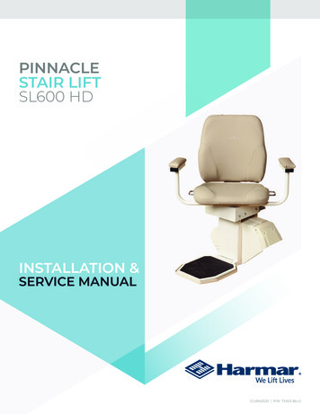
PINNACLESTAIR LIFTSL600 HDINSTALLATION &SERVICE MANUAL31JAN2020 P/N: 75403 Rev C
HEAVY DUTY STAIR LIFTTABLE OF CONTENTSTable of ContentsINTRODUCTION . 4Device Name: Pinnacle SL600HD Stair Lift.4Read and Understand .4Technical Specifications. 4SAFETY. 5Safety Definitions .5Required Practices.5PREPARATION . 6Required Tools .6Unpacking the Lift .6Checking the Box Contents.7Included Parts .7PREPARATION . 8Determine Overall Rail Length . 8INSTALLATION. 9Rail Installation . 9Chassis Installation . 10Final Rail Installation . 11Footrest & Seat Installation . 12Remote Control Programming . 14Final Testing . 15SL600HD Heavy Duty Stair Lift: Installation & Service Manual31JAN2020 P/N: 75403 REV C3
HEAVY DUTY STAIR LIFT: SECTION 1INTRODUCTIONSection 1IntroductionDEVICE NAME: PINNACLESL600 HD STAIR LIFTTECHNICAL SPECIFICATIONSIndications of Use: The intended use of the PinnacleSL600 HD Stair Lift is to assist the transfer of patientsor mobility impaired persons, up and down levels of aresidence.Rated Load:600 lbIncline Limits:32 to 45 Speed:14 fpmREAD AND UNDERSTANDThis manual provides instructions for proper use andmaintenance of your Pinnacle SL600 HD Stair Lift.Please refer to this Owner’s Manual for operatinginstructions. Any alterations to the equipmentwithout written authorization by the manufacturer isprohibited and will void the warranty.4Indoor Use OnlySwitchable side to side: YesPower Supply:24V DC, 2 AmpsCharger Input:120V AC grounded outletDrive System:Plastic Worm/RackSafety Standards:Safety Standards forPlatform Lifts and StairwayChairlifts - ASME A18.12017Elevator and EscalatorEquipment - ASME A17.52014/CSA B44.1-2014ETL ListedSafety Devices:Centrifugal OverspeedBreakBi-Directional FootrestObstruction SensorsSwivel Seat Cut-Off SwitchFinal LimitsUp/Down LimitsSeat BeltChassis Obstruction SensorsMotor BrakeBattery Breaker SwitchOptional Equipment:Retractable Seat BeltKey LockExtra RailSL600HD Heavy Duty Stair Lift: Installation & Service Manual31JAN2020 P/N: 75403 REV C
HEAVY DUTY STAIR LIFT: SECTION 2SAFETYSection 2SafetySAFETY DEFINITIONSREQUIRED PRACTICESThis safety alert symbol appears withsafety statements. It means attention,become alert, your safety is involved!Please read and abide by the messagethat follows the safety alert symbol.NOTE: Installation of this lift requires one person, aslong as the one person follows installation instructions,has completed training, has obtained certification oninstallation, is able to instruct the user on the correctoperation and has established a safety and maintenanceschedule.!!WARNINGEnvironmental ConditionsIndicates a hazardous situation that, if notavoided, could result in death or serious injury.!The technician shall assess the surroundingconditions and verify that the location is acceptablebefore performing installation and/or servicing tasks.NOTE: If you do not understand any portion of theinstallation or operation procedures, please consult ourTechnical Service Department or authorized dealer. Do notattempt to install or use this lift if you have any hesitationor question. Serious injury or damage can result if properprocedures are not followed.CAUTIONIndicates a hazardous situation that, if notavoided, could result in minor or moderateinjury.NOTICEIndicates a situation which can cause damage tothe lift and/or the environment, or cause the lift tooperate improperly.NOTE: Indicates a condition that should be followed inorder for the lift to function in the manner intended.SL600HD Heavy Duty Stair Lift: Installation & Service Manual31JAN2020 P/N: 75403 REV C5
HEAVY DUTY STAIR LIFT: SECTION 3PREPARATIONSection 3PreparationInstallations may vary to some degree, but below arethe basic tools to have on hand for a Pinnacle StairLift installation.UNPACKING THE LIFTIf you have any questions, concerns or comments,please contact our Technical Service Department at800-378-6648 or tech@harmar.com.REQUIRED TOOLS Allen Wrench: 5/64" 5/32" 3/16" 5/16" Cordless Drill Nut Driver: 3/8" 5/16" 6"-10" Driver Extension Level Hack Saw or Chop Saw SAE Socket Set SAE Wrenches Tape Measure6SL600HD Heavy Duty Stair Lift: Installation & Service Manual31JAN2020 P/N: 75403 REV CNever attempt to pick up the lift fromthe box, ground or on/off a vehiclealone.
HEAVY DUTY STAIR LIFT: SECTION 3PREPARATIONCHECKING THE BOXCONTENTSBefore installing the lift, review each part against thepackaging checklist to ensure that all parts have beenincluded. If any parts are missing or damaged, immediatelycontact the dealer who sold the lift. DO NOT attempt toinstall or use a lift that has missing or damaged parts.INCLUDED PARTS Chassis Box: Rail Box: Chassis Bottom Rail Pre-installation with BottomEnd Plate and Charge Strip Wire Harness Call/Send Parts Bottom Limit Cam 2 Call/Send Hand Controls Joint Pins and Joint Brackets (two-piece railonly) Battery Charger Installation Manual Plastic Gear Rack Owner’s Manual Top Rail Pre-installed with Charge StripWire Harness Rail Bracket Box: Rail Brackets (2, 3, 4, or 6 per set) Wood Screws (#14 x 2" (4 per rail bracket) Rail Accessories (Plastic Bag) with Top EndPlate and Compression Bolts (2 sizes) Self-cutting screws ( 1/4" - 20 x 1") Chair Box: Chair Torx T30 Driver Bit Back Rest Rail Parts (Plastic Bag) with Extra PlasticRacks (2 or 3) and Top Limit Cam Seat Belt Footrest Box: Footrest complete with Swivel Slide Railsand Swivel Pin Bracket Rear Seat SupportSL600HD Heavy Duty Stair Lift: Installation & Service Manual31JAN2020 P/N: 75403 REV C7
HEAVY DUTY STAIR LIFT: SECTION 3PREPARATIONDETERMINE OVERALL RAILLENGTH (ONLY IF TRACK DID NOTCOME PRE-CUT TO LENGTH)1. Determine obstructions that will affect theposition and length of the rail, such as walls,doors, hallway orientation, etc.2. Measure the overall length of the stairs from thenose at the top landing to the floor (nose to floormeasurement). See Figure 3-1.Extension7"9"11"13"Horizontal intrusion on top landing3.9"5"6.1"7.2"Figure 3-25. To cut the rail, use a standard 12" chop saw, witha blade designed to cut aluminum.NOTICEDo not cut the rail inside the house (aluminum chipsare very hard to remove from carpets).!WARNINGDo not cut the end of the rail that contains thejoint holes. Remove the charger strips and wireharness before cutting.Figure 3-13. For a normal stairway with adequate landingspace, add 7" to the nose to floor measurement.This will provide enough rail length to allow thestair lift to be adjusted so that the floor-to-seatheight will be the same at both the top and thebottom.4. If the top landing has restrictions (i.e. a wall or adoorway), use the chart to determine the lengthof extensions needed. See Figure 3-2.8SL600HD Heavy Duty Stair Lift: Installation & Service Manual31JAN2020 P/N: 75403 REV C
HEAVY DUTY STAIR LIFT: SECTION 4INSTALLATIONSection 4Installation6. Turn over joined rails and install the remainingtwo join fasteners and firmly tighten with 3/16"Allen wrench. Then slide track pieces down tocover the joint.RAIL INSTALLATION1. Open the rail box and remove its contents.2. Position the bottom rail (with end plate attached)directly on the stairs with the end plate towardsthe bottom of the stairs and the plastic rackfacing up. Place an object the measures between3/4" and 1" between end plate and floor.7. Install the rail brackets by loosing the screws andsnapping each bracket edge into the slot, or slidethe brackets on from the top of the rail.See Figure 4-2.NOTE: Use the chair box or another heavy object, likea toolbox, at the bottom to prevent the rail from slidingdown the stairs.3. Position the two ends of the track closetogether. Locate and connect the plug on theends of the two charger harness inside the twotrack pieces.4. With the plastic rack facing up, sliding the toprail into the bottom rail and guide them togetherusing the pre-installed pins. Gently tap the toprail if necessary to get them close together. Becautious not to pinch the charger harness.5. Install two joint fasteners and firmly tighten with3/16" Allen wrench. Then slide rack pieces down tocover joint. See Figure 4-1.Figure 4-28. For double rails, tighten the first rail brackets inplace so, when it’s turned over, the back of thebracket touches the rear of the bottom step.Place and tighten the second and third bracketson the steps on each side of the rail joint, againso the back of the bracket touches the rear ofthe step. Place the fourth and final bracket onthe top step before the landing, again tighteningit so it touches the front of the last step.See Figure 4-3.Figure 4-3Figure 4-1Tighten the first rail bracket in place so whenturned over the back of the bracket touches therear of the first step from the bottom landing.SL600HD Heavy Duty Stair Lift: Installation & Service Manual31JAN2020 P/N: 75403 REV C9
HEAVY DUTY STAIR LIFT: SECTION 4INSTALLATIONPlace the other rail on the last step before thetop landing, again tightening it so it touches therear of the last step. See Figure 4-4.clearance, and hold the rail in place, secure thebottom bracket to the first step from the floorwith two 2" wood screws, using a 3/8" nut driveron a 6"-10" extension of a cordless drill.CHASSIS INSTALLATIONNOTICEFigure 4-49. Turn the rail right side up with the plastic sidefacing up. See Figure 4-5.Remove two pieces of gear rack from the top end ofthe track before installing the chassis.1. Remove the plastic bag from the chassis box.Lift the chassis with the manual override hole(on bottom) facing the downhill side of the stairsand gently slide the chassis onto the rail until itmakes contact with the plastic rack. DO NOTLET THE CHASSIS FALL DOWN THE RAIL.See Figure 4-7.Figure 4-510. Measure any obstruction from the wall (this mayinclude handrails, molding, light switches, etc.)and adjust the edge of the brackets and equaldistance from the wall. The edge of the trackneeds to be 7" from the wall or any obstruction.See Figure 4-6.Figure 4-7!CAUTIONBe careful not to trap fingers between the railand the chassis.Figure 4-62. Remove the safety tie and turn the red “On/OFF”switch to the “ON” position. See Figure 4-8.11. The underside of the rail must be at least 2"above the stair tread nose to provide clearancefor the footrest. To achieve this 2" clearancemove the rail and bracket forward. Once theclearance is 2" tighten all bracket nuts to holdthe brackets in position. To maintain the 2"10SL600HD Heavy Duty Stair Lift: Installation & Service Manual31JAN2020 P/N: 75403 REV CFigure 4-8
HEAVY DUTY STAIR LIFT: SECTION 4INSTALLATION3. Use the installation switch (the black switch onthe top of the chassis) to move the chassis atleast two feet down the rail, pushing gently onthe chassis to ensure the chassis does not pullany rack to the top. See Figure 4-9.Figure 4-113. Slide the top limit cam into one of the cam slots(either side), and tighten the pre-inserted Allenscrew with a 5/64 Allen wrench. This will beused to set the final upper limits for the stair lift.See Figure 4-12.Figure 4-9!CAUTIONDo not ride on the chassis or lift until the installis complete.FINAL RAIL INSTALLATION1. Install the remaining plastic rack pieces in theupper rail. See Figure 4-10.Figure 4-102. Use a hacksaw or chop saw to cut the lastplastic rack piece flush with the rail end. Placesomething on the floor to catch debris or markand cut the rack outside.The exposed, cut end of the plastic rack shouldface the top end of the rail (the factory-cut sideshould butt against the lower rack).See Figure 4-11.Figure 4-124. Remove the charging strip from the rail box.Connect charging strip connector to the chargerwire that runs through the center of the rail fromthe lower charging strips.Insert the two charger strips into the keyed slotsat the top of the rail (while standing on the toplanding looking down). The charging strip withthe red wire should be inserted into the left slotwith the metal strip facing out. The chargingstrip with the black wire should be inserted intothe right slot with the metal strip pointing out.Bend the red and black wire tabs in toward thecenter of the rack.Insert excess cable into the rail, leaving thepigtail with the Molex connector.5. Install the end plate to the top of the rack withthe four self-cutting Torx screws using thesupplied T30 Torx bit. See Figure 4-13.SL600HD Heavy Duty Stair Lift: Installation & Service Manual31JAN2020 P/N: 75403 REV C11
HEAVY DUTY STAIR LIFT: SECTION 4INSTALLATIONFOOTREST & SEATINSTALLATIONFigure 4-13!CAUTION1. Remove footrest from box and use theinstallation switch to drive the chassisdownward to a position about 6" clear of thefloor. This provides a safe area to install andadjust the footrest. Do not drive the unit intothe bottom stop. See Figure 4-15.Too much torque applied to these screws mayresult in damage. Take your time and applygrease to threads.6. Install one of the rack pre-compression screwsin the threaded hole in the top rail plate; tightenas firmly as possibly by hand with a 5/32" Allenwrench. See Figure 4-14.There are three kinds of pre-compressionscrews: 1" for tracks under 6' 1 1/4" for tracks between 6' and overFigure 4-152. Turn the red “On/Off” switch located on the topof the chassis to the “OFF” position.3. Position the footrest onto the two seat-levelingbolts on the outside of the chassis by aligningthe large opening at the slot ends of the footrestSee Figure 4-16.Figure 4-147. Plug in the battery charger at either end of therail, choosing the closest or most convenientlocation of a wall power supply. Minimize wirelength and intrusion.12Figure 4-164. Ensure the footrest if fully engaged.5. Position the rear seat support onto the two seatleveling bolts on the backside of the chassis byaligning the large opening at the slot ends of thefootrest. See Figure 4-17.SL600HD Heavy Duty Stair Lift: Installation & Service Manual31JAN2020 P/N: 75403 REV C
HEAVY DUTY STAIR LIFT: SECTION 4INSTALLATION6. Connect the footrest cable to the 6-pinconnector on the chassis. See Figure 4-21.Figure 4-17Secure the rear seat support to the footrest/seat support using the two hex-head bolts andwashers. See Figure 4-18.Figure 4-21NOTE: When the 6-pin footrest and the 8-pin chair cablesare both connected to the chassis, the black installationswitch on the chassis is disabled and will not function.7. Align the seat rollers with the slider rails andslide the seat half way back. See Figure 4-22.Figure 4-18Secure the rear of the slider rails to the rearsupport using the two socket bolts.See Figure 4-19.Figure 4-228. Swivel seat approximately 45 to one side.See Figure 4-23.Figure 4-19Ensure that the seat support is level and tightenthe two front and two rear leveling bolts.See Figure 4-20.Figure 4-239. Attach the swivel pin bracket with the flat sidetowards the footrest support using the two hexhead bolts and washers. Ensure that one of theswivel pins is engaged into the slot in the swivelcam. See Figure 4-24.Figure 4-20SL600HD Heavy Duty Stair Lift: Installation & Service Manual31JAN2020 P/N: 75403 REV C13
HEAVY DUTY STAIR LIFT: SECTION 4INSTALLATIONnot green after testing sensors, turn the unitoff and re-check all wire plugs. Turn the unit onagain and re-check the LED indicator light cycle.When the LED indicator light remains green, thelift is ready to operate. See Figure 4-27.Figure 4-2410. Connect the seat cable to the 8-pin connectoron the chassis. See Figure 4-25.Seat swivel sensorSeat should be in thelocked positionFootrest lower sensorCheck by pushing in onthe safety pan on thefootrestUpper foot pan safetysensorCheck by pushing onthe safety pan on thefootrestFront foot pan safetysensorCheck by pushing onthe safety pan on thefootrestUphill safety sensorEnsure nothing isblocking upwardpassageDownhill safety sensorEnsure nothing isblocking downwardpassageFigure 4-2511. If the lift is equipped with the optional keylock, ensure that the key switch on the armrestcontrol is in the locked position; the key shouldbe in the vertical position. See Figure 4-26.Figure 4-27REMOTE CONTROLPROGRAMMINGFigure 4-2612. Turn the red “ON/OFF” switch located on thetop of the chassis to the “ON” position. Youshould hear a single beep and the LED indicatorlight on the armrest control should cycle througha test sequence, showing red, yellow and greenrespectively. If any of the system controls orsafety sensors are engaged the LED indicatorlight will turn to yellow.13. If the LED indicator light is not green, check thesafety sensors. If the LED indicator light is still14All call/send controls are factory programmed.Re-programming is not normally necessary duringinstallation. In the event that the remove call/sendcontrol needs to be re-programmed, it is essential toprogram BOTH controls in one programming cycle.Do so by completing the following.1. Start with the red “ON/OFF” switch in the “Off”position.2. Disconnect the 6-pin footrest and 8-pin chairwire harness from the chassis.3. Press and hold the install switch (located on theSL600HD Heavy Duty Stair Lift: Installation & Service Manual31JAN2020 P/N: 75403 REV C
HEAVY DUTY STAIR LIFT: SECTION 4INSTALLATIONtop of the chassis) in either direction.4. Turn the red “ON/OFF” switch to the “ON”position, and then release the install switch.5. The lift will begin to beep rapidly (this means thefirst remove control is ready to program).6. Press and release the “UP” or “DOWN” button ofthe first remote control (the first remote controlis now programmed).7. Press and release the “UP” or “DOWN” button ofthe second remote control (the second remotecontrol is now programmed).8. Upon completion, two beeps will indicate thatboth remote controls have been programmed.9. Turn the “ON/OFF” switch to the “OFF”position.10. Connect the 6-pin footrest and 8-pin chair wireharness to the chassis and then turn the red“ON/OFF” switch to the “ON” position.11. Test each remote control in both the up anddown directions.FINAL TESTINGTest Armrest Control Switch1. Ensure that the unit travels correctly byoperating the armrest control switch whilestanding in front of the unit.2. Depress the switch in the upstairs direction tomove up. The lift will beep, wait three secondsand begin to smoothly accelerate upwards. Thelift will continue to move upwards as long as theswitch is depressed.3. Release the switch and the lift will come to animmediate stop.4. Depress the switch in the downstairs directionto move down. The lift will beep, wait threeseconds and begin to move downwards.5. Release the switch and the lift will come to animmediate stop.6. Run the chair all the way up and down the railto ensure that the top of the seat back hasat least a 1/2" clearance from the wall and anyobstructions.Tighten Brackets1. Install and fully tighten the rail bracket mountingscrews (four screws per bracket). For hardwoodstairs, drill a pilot hole first. For plywood orparticle board stairs, take care to preventstripping.Set Upper and LowerTravel Limits1. Test the lower travel limit by operating the liftdownward, keeping the switch depressed. Theunit should begin to decelerate about 3" from itsfinal resting position and stop clear of the floor.2. The final stopped position can be adjustedto accommodate the height of the user byrepositioning the limit cam located in a slot inthe rail.3. Use a 5/64" Allen wrench to loosen the set screwin the limit cam. Adjust the limit cam up or downand retighten the set screws. Repeat the abovesteps until the lift stops in the desired position.4. Repeat the above steps to set the upper limits.For safety, the footrest should be set at leastlevel with the upper landing.5. The optimum position is met when the seatheight above the floor is the same at the top andbottom of the stairs.Test Safety Stop Switches1. Safety stop switches are located in both theupward and downward ends of the chassisSL600HD Heavy Duty Stair Lift: Installation & Service Manual31JAN2020 P/N: 75403 REV C15
HEAVY DUTY STAIR LIFT: SECTION 4INSTALLATIONproviding protection from obstructions on therail.2. Safety stop switches are located in thefootrest bottom pan providing protection fromobstructions and trapping hazards on the stairs.3. A safety stop switch is part of the swivel seatmechanism and prevents the lift from operatingwhen the swivel is in use.4. Test all the safety stop switches by driving thelift down and touching the downward end of thechassis, the lower edge of the footrest, and theunderside of the footrest in both its folded andunfolded positions.5. In each of the above cases the unit should cometo an immediate halt. The LED indicator light onthe armrest control should turn to orange andthe unit should beep intermittently.6. When the control switch is released, the unitshould NOT be able to be driven in the directionthat the lift initially engaged the obstacle. Testthis condition.7. Test to ensure that the lift can only be drivenaway from the obstruction. The LED indicatorlight will turn to green and stop beepingindicating a safe operating condition.8. Repeat the above tests while driving the lift inopposite direction.9. If any safety condition does not functionproperly, carefully review all installationinstructions, reset the “ON/OFF” switch andcheck that the LED indicator light is green.Repeat the above tests.10. If any safety stop switch fails to immediatelystop the lift and/or a red LED indicator lightappears, remove the key to prevent further useof the lift and immediately call the manufacturerfor assistance in diagnosing and repairing theproblem. DO NOT USE THE LIFT.16Additional System Checks1. After the successful testing of all safetyswitches, secure the seat belt, sit on the lift andoperate to the top of the stairs. Keeping thecontrol switch depressed continuously, the liftshould gently decelerate and then stop at thetop of the track.2. As a final adjustment, sit on the lift and do twocomplete up trips and stop with the chair at thebottom. Then tighten the compression screw inthe top end plate, then run the chair to the topand again tighten the compression screw. Runthe chair to the middle and do a final tighteningof the compression screw.3. Drive the lift to the bottom, keeping the controlswitch depressed all the time, and check that thelift gently decelerate and stops so the footrestpan is clear off the floor. If necessary adjust thelimit cams with a 5/64" Allen wrench.4. Move the lift about three (3) feet from either thetop or bottom of the rail. After 30 seconds thearmrest LED indicator light will show orangeand beep indicating that the lift is not positionedon a charge point. The beep will stop after 30seconds, but the armrest LED indicator light willcontinue to flash orange.5. Test the seat swivel at the top by using thelevers and swiveling the seat towards thelanding and stop the seat at 35 and 85 degrees.The seat swivel levers will release into a lockedposition at each of these angles. The lift will notoperate in any of these positions if the controlswitch is depressed, and the LED indicator lightwill turn orange. Return the seat to its normalposition and the LED indicator light will turngreen and the lift will now operate normally.6. Drive to the top or bottom and check the batterycharging light. If the light is orange or red, thebatteries are being charged.SL600HD Heavy Duty Stair Lift: Installation & Service Manual31JAN2020 P/N: 75403 REV C
NOTESSL600HD Heavy Duty Stair Lift: Installation & Service Manual31JAN2020 P/N: 75403 REV C17
NOTES18SL600HD Heavy Duty Stair Lift: Installation & Service Manual31JAN2020 P/N: 75403 REV C
NOTESSL600HD Heavy Duty Stair Lift: Installation & Service Manual31JAN2020 P/N: 75403 REV C19
2075 47th Street Sarasota, FL 34234800.833.0478harmar.com
SL600 HD Stair Lift is to assist the transfer of patients or mobility impaired persons, up and down levels of a residence. READ AND UNDERSTAND This manual provides instructions for proper use and maintenance of your Pinnacle SL600 HD Stair Lift. Please refer to this Owner's Manual for operating instructions. Any alterations to the equipment


