Transcription
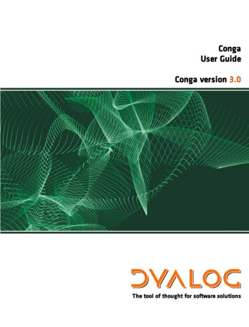
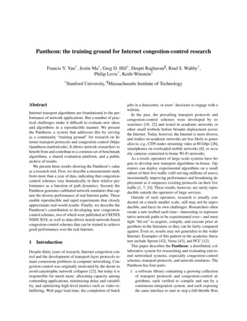
CONGA: Distributed Congestion-Aware Load Balancingfor DatacentersMohammad Alizadeh, Tom Edsall, Sarang Dharmapurikar, Ramanan Vaidyanathan, Kevin Chu,Andy Fingerhut, Vinh The Lam (Google), Francis Matus, Rong Pan, Navindra Yadav,George Varghese (Microsoft)Cisco SystemsABSTRACTWe present the design, implementation, and evaluation of CONGA,a network-based distributed congestion-aware load balancing mechanism for datacenters. CONGA exploits recent trends includingthe use of regular Clos topologies and overlays for network virtualization. It splits TCP flows into flowlets, estimates real-timecongestion on fabric paths, and allocates flowlets to paths basedon feedback from remote switches. This enables CONGA to efficiently balance load and seamlessly handle asymmetry, without requiring any TCP modifications. CONGA has been implemented incustom ASICs as part of a new datacenter fabric. In testbed experiments, CONGA has 5 better flow completion times than ECMPeven with a single link failure and achieves 2–8 better throughput than MPTCP in Incast scenarios. Further, the Price of Anarchy for CONGA is provably small in Leaf-Spine topologies; henceCONGA is nearly as effective as a centralized scheduler while being able to react to congestion in microseconds. Our main thesisis that datacenter fabric load balancing is best done in the network,and requires global schemes such as CONGA to handle asymmetry.Categories and Subject Descriptors: C.2.1 [Computer-CommunicationNetworks]: Network Architecture and DesignKeywords: Datacenter fabric; Load balancing; Distributed1.INTRODUCTIONDatacenter networks being deployed by cloud providers as wellas enterprises must provide large bisection bandwidth to supportan ever increasing array of applications, ranging from financial services to big-data analytics. They also must provide agility, enablingany application to be deployed at any server, in order to realizeoperational efficiency and reduce costs. Seminal papers such asVL2 [18] and Portland [1] showed how to achieve this with Clostopologies, Equal Cost MultiPath (ECMP) load balancing, and thedecoupling of endpoint addresses from their location. These design principles are followed by next generation overlay technologies that accomplish the same goals using standard encapsulationssuch as VXLAN [35] and NVGRE [45].However, it is well known [2, 41, 9, 27, 44, 10] that ECMP canbalance load poorly. First, because ECMP randomly hashes flowsPermission to make digital or hard copies of all or part of this work for personal orclassroom use is granted without fee provided that copies are not made or distributedfor profit or commercial advantage and that copies bear this notice and the full citation on the first page. Copyrights for components of this work owned by others thanACM must be honored. Abstracting with credit is permitted. To copy otherwise, or republish, to post on servers or to redistribute to lists, requires prior specific permissionand/or a fee. Request permissions from permissions@acm.org.SIGCOMM’14, August 17–22, 2014, Chicago, IL, USA.Copyright 2014 ACM 978-1-4503-2836-4/14/08 . 15.00.http://dx.doi.org/10.1145/2619239.2626316 .to paths, hash collisions can cause significant imbalance if there area few large flows. More importantly, ECMP uses a purely local decision to split traffic among equal cost paths without knowledge ofpotential downstream congestion on each path. Thus ECMP farespoorly with asymmetry caused by link failures that occur frequentlyand are disruptive in datacenters [17, 34]. For instance, the recentstudy by Gill et al. [17] shows that failures can reduce deliveredtraffic by up to 40% despite built-in redundancy.Broadly speaking, the prior work on addressing ECMP’s shortcomings can be classified as either centralized scheduling (e.g.,Hedera [2]), local switch mechanisms (e.g., Flare [27]), or hostbased transport protocols (e.g., MPTCP [41]). These approachesall have important drawbacks. Centralized schemes are too slowfor the traffic volatility in datacenters [28, 8] and local congestionaware mechanisms are suboptimal and can perform even worsethan ECMP with asymmetry (§2.4). Host-based methods such asMPTCP are challenging to deploy because network operators oftendo not control the end-host stack (e.g., in a public cloud) and evenwhen they do, some high performance applications (such as lowlatency storage systems [39, 7]) bypass the kernel and implementtheir own transport. Further, host-based load balancing adds morecomplexity to an already complex transport layer burdened by newrequirements such as low latency and burst tolerance [4] in datacenters. As our experiments with MPTCP show, this can make forbrittle performance (§5).Thus from a philosophical standpoint it is worth asking: Canload balancing be done in the network without adding to the complexity of the transport layer? Can such a network-based approachcompute globally optimal allocations, and yet be implementable ina realizable and distributed fashion to allow rapid reaction in microseconds? Can such a mechanism be deployed today using standard encapsulation formats? We seek to answer these questionsin this paper with a new scheme called CONGA (for CongestionAware Balancing). CONGA has been implemented in custom ASICsfor a major new datacenter fabric product line. While we report onlab experiments using working hardware together with simulationsand mathematical analysis, customer trials are scheduled in a fewmonths as of the time of this writing.Figure 1 surveys the design space for load balancing and placesCONGA in context by following the thick red lines through the design tree. At the highest level, CONGA is a distributed scheme toallow rapid round-trip timescale reaction to congestion to cope withbursty datacenter traffic [28, 8]. CONGA is implemented within thenetwork to avoid the deployment issues of host-based methods andadditional complexity in the transport layer. To deal with asymmetry, unlike earlier proposals such as Flare [27] and LocalFlow [44]that only use local information, CONGA uses global congestioninformation, a design choice justified in detail in §2.4.
ost- ‐BasedIn- ‐NetworkLocal(StatelessorConges6on- ‐Aware)Global,Conges6on- x,hardtoNear- ‐op malfor2- ‐ er,deploydeployablewithanoverlayPerFlowSubop malfor“heavy”flowdistribu a ons,resilienttoflowdistribu onPerPacketOp mal,needsreordering- ‐resilientTCPFigure 1: Design space for load balancing.Next, the most general design would sense congestion on everylink and send generalized link state packets to compute congestionsensitive routes [16, 48, 51, 36]. However, this is an N-party protocol with complex control loops, likely to be fragile and hard todeploy. Recall that the early ARPANET moved briefly to suchcongestion-sensitive routing and then returned to static routing, citing instability as a reason [31]. CONGA instead uses a 2-party“leaf-to-leaf” mechanism to convey path-wise congestion metricsbetween pairs of top-of-the-rack switches (also termed leaf switches)in a datacenter fabric. The leaf-to-leaf scheme is provably nearoptimal in typical 2-tier Clos topologies (henceforth called LeafSpine), simple to analyze, and easy to deploy. In fact, it is deployable in datacenters today with standard overlay encapsulations(VXLAN [35] in our implementation) which are already being usedto enable workload agility [33].With the availability of very high-density switching platformsfor the spine (or core) with 100s of 40Gbps ports, a 2-tier fabric canscale upwards of 20,000 10Gbps ports.1 This design point coversthe needs of the overwhelming majority of enterprise datacenters,which are the primary deployment environments for CONGA.Finally, in the lowest branch of the design tree, CONGA is constructed to work with flowlets [27] to achieve a higher granularityof control and resilience to the flow size distribution while not requiring any modifications to TCP. Of course, CONGA could alsobe made to operate per packet by using a very small flowlet inactivity gap (see §3.4) to perform optimally with a future reorderingresilient TCP.In summary, our major contributions are: We design (§3) and implement (§4) CONGA, a distributedcongestion-aware load balancing mechanism for datacenters.CONGA is immediately deployable, robust to asymmetriescaused by link failures, reacts to congestion in microseconds,and requires no end-host modifications. We extensively evaluate (§5) CONGA with a hardware testbedand packet-level simulations. We show that even with a singlelink failure, CONGA achieves more than 5 better flow completion time and 2 better job completion time respectivelyfor a realistic datacenter workload and a standard Hadoop Distributed File System benchmark. CONGA is at least as goodas MPTCP for load balancing while outperforming MPTCPby 2–8 in Incast [47, 12] scenarios. We analyze (§6) CONGA and show that it is nearly optimalin 2-tier Leaf-Spine topologies using “Price of Anarchy” [40]1analysis. We also prove that load balancing behavior and theeffectiveness of flowlets depends on the coefficient of variation of the flow size distribution.DistributedFor example, spine switches with 576 40Gbps ports can be pairedwith typical 48-port leaf switches to enable non-blocking fabricswith 27,648 10Gbps ports.2.DESIGN DECISIONSThis section describes the insights that inform CONGA’s majordesign decisions. We begin with the desired properties that haveguided our design. We then revisit the design decisions shown inFigure 1 in more detail from the top down.2.1Desired PropertiesCONGA is an in-network congestion-aware load balancing mechanism for datacenter fabrics. In designing CONGA, we targeted asolution with a number of key properties:1. Responsive: Datacenter traffic is very volatile and bursty [18,28, 8] and switch buffers are shallow [4]. Thus, with CONGA,we aim for rapid round-trip timescale (e.g., 10s of microseconds) reaction to congestion.2. Transport independent: As a network mechanism, CONGAmust be oblivious to the transport protocol at the end-host(TCP, UDP, etc). Importantly, it should not require any modifications to TCP.3. Robust to asymmetry: CONGA must handle asymmetry dueto link failures (which have been shown to be frequent anddisruptive in datacenters [17, 34]) or high bandwidth flowsthat are not well balanced.4. Incrementally deployable: It should be possible to applyCONGA to only a subset of the traffic and only a subset ofthe switches.5. Optimized for Leaf-Spine topology: CONGA must workoptimally for 2-tier Leaf-Spine topologies (Figure 4) that coverthe needs of most enterprise datacenter deployments, thoughit should also benefit larger topologies.2.2Why Distributed Load Balancing?The distributed approach we advocate is in stark contrast to recently proposed centralized traffic engineering designs [2, 9, 23,21]. This is because of two important features of datacenters. First,datacenter traffic is very bursty and unpredictable [18, 28, 8]. CONGAreacts to congestion at RTT timescales ( 100µs) making it moreadept at handling high volatility than a centralized scheduler. Forexample, the Hedera scheduler in [2] runs every 5 seconds; but itwould need to run every 100ms to approach the performance ofa distributed solution such as MPTCP [41], which is itself outperformed by CONGA (§5). Second, datacenters use very regular topologies. For instance, in the common Leaf-Spine topology(Figure 4), all paths are exactly two-hops. As our experiments (§5)and analysis (§6) show, distributed decisions are close to optimal insuch regular topologies.Of course, a centralized approach is appropriate for WANs wheretraffic is stable and predictable and the topology is arbitrary. Forexample, Google’s inter-datacenter traffic engineering algorithmneeds to run just 540 times per day [23].2.3Why In-Network Load Balancing?Continuing our exploration of the design space (Figure 1), thenext question is where should datacenter fabric load balancing beimplemented — the transport layer at the end-hosts or the network?
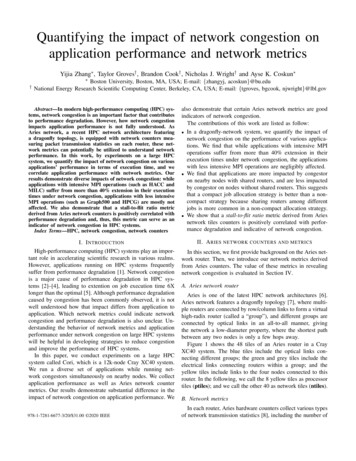
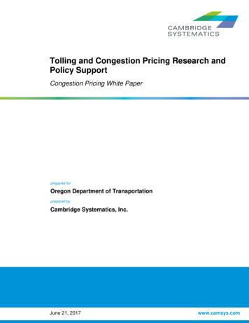
33.340L080S04040S1S1(a) Static (ECMP)(b) Congestion-Aware:Local Only(c) Congestion-Aware:Global (CONGA)Figure 2: Congestion-aware load balancing needs non-local information with asymmetry. Here, L0 has 100Gbps of TCP traffic to L1, and the (S1, L1) link has half the capacity of theother links. Such cases occur in practice with link-aggregation(which is very common), for instance, if a link fails in a fabricwith two 40Gbps links connecting each leaf and spine switch.40L140S04040L1(a) L0 L2 0, L1 L2 804040L240S1404040L240S1L040S1(b) L0 L2 40, L1 L2 40Figure 3: Optimal traffic split in asymmetric topologies depends on the traffic matrix. Here, the L1 L2 flow must adjustits traffic through S0 based on the amount of L0 L2 traffic.Per- ‐linkConges*onMeasurementSpine TierThe state-of-the-art multipath transport protocol, MPTCP [41],splits each connection into multiple (e.g., 8) sub-flows and balances traffic across the sub-flows based on perceived congestion.Our experiments (§5) show that while MPTCP is effective for loadbalancing, its use of multiple sub-flows actually increases congestion at the edge of the network and degrades performance in Incastscenarios (Figure 13). Essentially, MPTCP increases the burstinessof traffic as more sub-flows contend at the fabric’s access links.Note that this occurs despite MPTCP’s coupled congestion controlalgorithm [50] which is designed to handle shared bottlenecks, because while the coupled congestion algorithm works if flows arein steady-state, in realistic datacenter workloads, many flows areshort-lived and transient [18].The larger architectural point however is that datacenter fabricload balancing is too specific to be implemented in the transportstack. Datacenter fabrics are highly-engineered, homogenous systems [1, 34]. They are designed from the onset to behave like agiant switch [18, 1, 25], much like the internal fabric within largemodular switches. Binding the fabric’s load balancing behavior tothe transport stack which already needs to balance multiple important requirements (e.g., high throughput, low latency, and burst tolerance [4]) is architecturally unappealing. Further, some datacenterapplications such as high performance storage systems bypass thekernel altogether [39, 7] and hence cannot use MPTCP.2.4Why Global Congestion Awareness?Next, we consider local versus global schemes (Figure 1). Handling asymmetry essentially requires non-local knowledge aboutdownstream congestion at the switches. With asymmetry, a switchcannot simply balance traffic based on the congestion of its locallinks. In fact, this may lead to even worse performance than a staticscheme such as ECMP (which does not consider congestion at all)because of poor interaction with TCP’s control loop.As an illustration, consider the simple asymmetric scenario inFigure 2. Leaf L0 has 100Gbps of TCP traffic demand to LeafL1. Static ECMP splits the flows equally, achieving a throughputof 90Gbps because the flows on the lower path are bottleneckedat the 40Gbps link (S1, L1). Local congestion-aware load balancing is actually worse with a throughput of 80Gbps. This is because as TCP slows down the flows on the lower path, the link(L0, S1) appears less congested. Hence, paradoxically, the localscheme shifts more traffic to the lower link until the throughputon the upper link is also 40 Gbps. This example illustrates a fundamental limitation of any local scheme (such as Flare [27], LocalFlow [44], and packet-spraying [10]) that strictly enforces anequal traffic split without regard for downstream congestion. eaf012 3?DestinationLeafGapFlowletDetec*onFigure 4: CONGA architecture. The source leaf switch detects flowlets and routes them via the least congested path tothe destination using congestion metrics obtained from leaf-toleaf feedback. Note that the topology could be asymmetric.course, global congestion-aware load balancing (as in CONGA)does not have this issue.The reader may wonder if asymmetry can be handled by someform of oblivious routing [32] such as weighted random load balancing with weights chosen according to the topology. For instance, in the above example we could give the lower path halfthe weight of the upper path and achieve the same traffic split asCONGA. While this works in this case, it fails in general becausethe “right” traffic splits in asymmetric topologies depend also onthe traffic matrix, as shown by the example in Figure 3. Here, depending on how much L0 L2 traffic there is, the optimal split forL1 L2 traffic changes. Hence, static weights cannot handle bothcases in Figure 3. Note that in this example, the two L1 L2 pathsare symmetric when considered in isolation. But because of anasymmetry in another part of the network, the L0 L2 traffic creates a bandwidth asymmetry for the L1 L2 traffic that can onlybe detected by considering non-local congestion. Note also that alocal congestion-aware mechanism could actually perform worsethan ECMP; for example, in the scenario in part (b).2.5Why Leaf-to-Leaf Feedback?At the heart of CONGA is a leaf-to-leaf feedback mechanismthat conveys real-time path congestion metrics to the leaf switches.The leaves use these metrics to make congestion-aware load balancing decisions based on the global (fabric-wide) state of congestion (Figure 4). We now argue (following Figure 1) why leaf-to-leafcongestion signaling is simple and natural for modern data centers.Overlay network: CONGA operates in an overlay network consisting of “tunnels” between the fabric’s leaf switches. When anendpoint (server or VM) sends a packet to the fabric, the sourceleaf, or source tunnel endpoint (TEP), looks up the destination end-
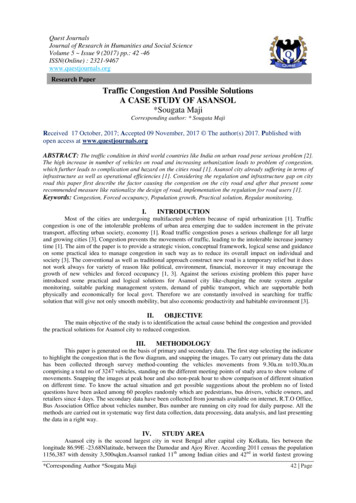
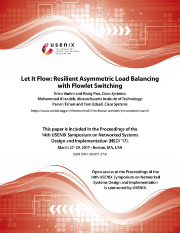
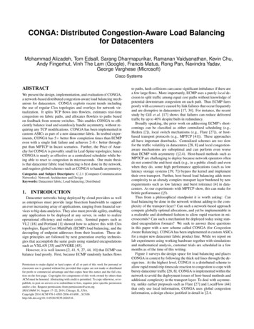
2.6Why Flowlet Switching for Datacenters?CONGA also employs flowlet switching, an idea first introducedby Kandula et al. [27]. Flowlets are bursts of packets from a flowthat are separated by large enough gaps (see Figure 4). Specifically, if the idle interval between two bursts of packets is largerthan the maximum difference in latency among the paths, then thesecond burst can be sent along a different path than the first without reordering packets. Thus flowlets provide a higher granularityalternative to flows for load balancing (without causing Flowlet(100μs)0.40.201.E 011.E 031.E 051.E 071.E 09Size(Bytes)Figure 5: Distribution of data bytes across transfer sizes fordifferent flowlet inactivity gaps.flows through the network core. The cluster supports over 2000diverse enterprise applications, including web, data-base, security,and business intelligence services. The captures are obtained byhaving a few leaf switches mirror traffic to an analyzer without disrupting production traffic. Overall, we analyze more than 150GBof compressed packet trace data.Flowlet size: Figure 5 shows the distribution of the data bytes versus flowlet size for three choices of flowlet inactivity gap: 250ms,500µs, and 100µs. Since it is unlikely that we would see a gaplarger than 250ms in the same application-level flow, the line “Flow(250ms)” essentially corresponds to how the bytes are spread acrossflows. The plot shows that balancing flowlets gives significantlymore fine-grained control than balancing flows. Even with an inactivity gap of 500µs, which is quite large and poses little risk ofpacket reordering in datacenters, we see nearly two orders of magnitude reduction in the size of transfers that cover most of the data:50% of the bytes are in flows larger than 30MB, but this numberreduces to 500KB for “Flowlet (500µs)”.Flowlet concurrency: Since the required flowlet inactivity gap isvery small in datacenters, we expect there to be a small numberof concurrent flowlets at any given time. Thus, the implementation cost for tracking flowlets should be low. To quantify this, wemeasure the distribution of the number of distinct 5-tuples in ourpacket trace over 1ms intervals. We find that the number of distinct 5-tuples (and thus flowlets) is small, with a median of 130 anda maximum under 300. Normalizing these numbers to the average throughput in our trace ( 15Gbps), we estimate that even fora very heavily loaded leaf switch with say 400Gbps of traffic, thenumber of concurrent flowlets would be less than 8K. Maintaininga table for tracking 64K flowlets is feasible at low cost (§3.4).Measurement analysisFlowlet switching has been shown to be an effective techniquefor fine-grained load balancing across Internet paths [27], but howdoes it perform in datacenters? On the one hand, the very highbandwidth of internal datacenter flows would seem to suggest thatthe gaps needed for flowlets may be rare, limiting the applicabilityof flowlet switching. On the other hand, datacenter traffic is knownto be extremely bursty at short timescales (e.g., 10–100s of microseconds) for a variety of reasons such as NIC hardware offloadsdesigned to support high link rates [29]. Since very small flowletgaps suffice in datacenters to maintain packet order (because thenetwork latency is very low) such burstiness could provide sufficient flowlet opportunities.We study the applicability of flowlet switching in datacenters using measurements from actual production datacenters. We instrument a production cluster with over 4500 virtualized and bare metalhosts across 30 racks of servers to obtain packet traces of traffic2Frac%onofDataBytespoint’s address (either MAC or IP) to determine to which leaf (destination TEP) the packet needs to be sent.2 It then encapsulatesthe packet — with outer source and destination addresses set to thesource and destination TEP addresses — and sends it to the spine.The spine switches forward the packet to its destination leaf basedentirely on the outer header. Once the packet arrives at the destination leaf, it decapsulates the original packet and delivers it to theintended recipient.Overlays are deployed today to virtualize the physical networkand enable multi-tenancy and agility by decoupling endpoint identifiers from their location (see [38, 22, 33] for more details). However, the overlay also provides the ideal conduit for CONGA’s leafto-leaf congestion feedback mechanism. Specifically, CONGA leverages two key properties of the overlay: (i) The source leaf knowsthe ultimate destination leaf for each packet, in contrast to standardIP forwarding where the switches only know the next-hops. (ii)The encapsulated packet has an overlay header (VXLAN [35] inour implementation) which can be used to carry congestion metricsbetween the leaf switches.Congestion feedback: The high-level mechanism is as follows.Each packet carries a congestion metric in the overlay header thatrepresents the extent of congestion the packet experiences as ittraverses through the fabric. The metric is updated hop-by-hopand indicates the utilization of the most congested link along thepacket’s path. This information is stored at the destination leaf ona per source leaf, per path basis and is opportunistically fed backto the source leaf by piggybacking on packets in the reverse direction. There may be, in general, 100s of paths in a multi-tiertopology. Hence, to reduce state, the destination leaf aggregatescongestion metrics for one or more paths based on a generic identifier called the Load Balancing Tag that the source leaf inserts inpackets (see §3 for details).How the mapping between endpoint identifiers and their locations(leaf switches) is obtained and propagated is beyond the scope ofthis paper.3.DESIGNFigure 6 shows the system diagram of CONGA. The majority ofthe functionality resides at the leaf switches. The source leaf makesload balancing decisions based on per uplink congestion metrics,derived by taking the maximum of the local congestion at the uplinkand the remote congestion for the path (or paths) to the destinationleaf that originate at the uplink. The remote metrics are stored in theCongestion-To-Leaf Table on a per destination leaf, per uplink basis and convey the maximum congestion for all the links along thepath. The remote metrics are obtained via feedback from the destination leaf switch, which opportunistically piggybacks values inits Congestion-From-Leaf Table back to the source leaf. CONGAmeasures congestion using the Discounting Rate Estimator (DRE),a simple module present at each fabric link.Load balancing decisions are made on the first packet of eachflowlet. Subsequent packets use the same uplink as long as theflowlet remains active (there is not a sufficiently long gap). Thesource leaf uses the Flowlet Table to keep track of active flowletsand their chosen uplinks.
A BLBTag 2CE 4Per- ‐linkDREsinSpine1023LeafB3(Receiver)Per- ‐uplinkDREs?LBDecisionConges7on- ‐To- ‐LeafFlowletTableTableSourceLeafDestLeaf1. The source leaf sends the packet to the fabric with the LBTagfield set to the uplink port taken by the packet. It also sets theCE field to zero.ReversePathPktUplink01k- ‐1B 25ForwardPathPktB AFB LBTag 1FB Metric 5LeafA(Sender)To-Leaf Table at each leaf switch. We now describe the sequenceof events involved (refer to Figure 6 for an example).LBTag01k- ‐1A253Conges7on- ‐From- ‐LeafTableFigure 6: CONGA system diagram.3.1Packet formatCONGA leverages the VXLAN [35] encapsulation format usedfor the overlay to carry the following state: LBTag (4 bits): This field partially identifies the packet’spath. It is set by the source leaf to the (switch-local) port number of the uplink the packet is sent on and is used by the destination leaf to aggregate congestion metrics before they arefed back to the source. For example, in Figure 6, the LBTagis 2 for both blue paths. Note that 4 bits is sufficient becausethe maximum number of leaf uplinks in our implementation is12 for a non-oversubscribed configuration with 48 10Gbpsserver-facing ports and 12 40Gbps uplinks. CE (3 bits): This field is used by switches along the packet’spath to convey the extent of congestion. FB LBTag (4 bits) and FB Metric (3 bits): These two fieldsare used by destination leaves to piggyback congestion information back to the source leaves. FB LBTag indicates theLBTag the feedback is for and FB Metric provides its associated congestion metric.3.2Discounting Rate Estimator (DRE)The DRE is a simple module for measuring the load of a link.The DRE maintains a register, X, which is incremented for eachpacket sent over the link by the packet size in bytes, and is decremented periodically (every Tdre ) with a multiplicative factor α between 0 and 1: X X (1 α). It is easy to show that X isproportional to the rate of traffic over the link; more precisely, ifthe traffic rate is R, then X R · τ , where τ Tdre /α. TheDRE algorithm is essentially a first-order low pass filter applied topacket arrivals, with a (1 e 1 ) rise time of τ . The congestionmetric for the link is obtained by quantizing X/Cτ to 3 bits (C isthe link speed).The DRE algorithm is similar to the widely used ExponentialWeighted Moving Average (EWMA) mechanism. However, DREhas two key advantages over EWMA: (i) it can be implementedwith just one register (whereas EWMA requires two); and (ii) theDRE reacts more quickly to traffic bursts (because increments takeplace immediately upon packet arrivals) while retaining memory ofpast bursts. In the interest of space, we omit the details.3.3Congestion FeedbackCONGA uses a feedback loop between the source and destination leaf switches to populate the remote metrics in the Congestion-2. The packet is routed through the fabric to the destination leaf.3As it traverses each link, its CE field is updated if the link’scongestion metric (given by the DRE) is larger than the currentvalue in the packet.3. The CE field of the packet received at the destination leaf givesthe maximum link congestion along the packet’s path. Thisneeds to be fed back to the source leaf. But since a packetmay not be immediately available in the reverse direction, thedestination leaf stores the metric in the Congestion-From-LeafTable (on a per source leaf, per LBTag basis) while it waits foran opportunity to piggyback the feedback.4. When a packet is sent in the reverse direction, one metric fromthe Congestion-From-Leaf Table is inserted in its FB LBTagand FB Metric fields for the source leaf. The metric is chosen in round-robin fashion while, as an optimization, favoringthose metrics whose values have changed since the last timethey were fed back.5. Finally, the source leaf parses the feedback in the reverse packetand updates the Congestion-To-Leaf Table.It is important to note that though we have described the forwardand reverse packets separately for simplicity, every packet simultaneously carries both a metric for its forward path and a feedbackmetric. Also, while we could generate explicit feedback packets,we decided to use piggybacking because we only need a very smallnumber of packets for feedback. In fact, all metrics between a pairof leaf switches can be conveyed in at-most 12 packets (becausethere are 12 distinct LBTag values), with the average case beingmuch smaller because the metrics only change at network roundtrip timescales, not packet-timescales (see the discussion in §3.6regarding the DRE time constant).Metric aging: A potential issue with not having explicit feedbackpackets is that the metrics may become stale if sufficient traffic doesnot exit for piggybacking. To handle this, a simple aging mechanism is added where a metric that has not been updated for a longtime (e.g., 10ms) gradually decays to zero. This also guaranteesthat a path that appears to be congested is eventually probed again.3.4Flowlet DetectionFlow
as MPTCP for load balancing while outperforming MPTCP by 2-8 in Incast [47, 12] scenarios. We analyze (x6) CONGA and show that it is nearly optimal in 2-tier Leaf-Spine topologies using "Price of Anarchy" [40] 1For example, spine switches with 576 40Gbps ports can be paired with typical 48-port leaf switches to enable non-blocking fabrics