Transcription
Cisco Policy Suite 6.1 Operations GuideVersion 6.1May 26, 2014Cisco Systems, Inc. www.cisco.comCisco has more than 200 offices worldwide. Addresses, phone numbers, and fax numbers are listed on the Cisco website at www.cisco.com/go/offices.
THE SPECIFICATIONS AND INFORMATION REGARDING THE PRODUCTS IN THIS MANUAL ARE SUBJECT TO CHANGE WITHOUT NOTICE. ALLSTATEMENTS, INFORMATION, AND RECOMMENDATIONS IN THIS MANUAL ARE BELIEVED TO BE ACCURATE BUT ARE PRESENTED WITHOUTWARRANTY OF ANY KIND, EXPRESS OR IMPLIED. USERS MUST TAKE FULL RESPONSIBILITY FOR THEIR APPLICATION OF ANY PRODUCTS.THE SOFTWARE LICENSE AND LIMITED WARRANTY FOR THE ACCOMPANYING PRODUCT ARE SET FORTH IN THE INFORMATION PACKET THATSHIPPED WITH THE PRODUCT AND ARE INCORPORATED HEREIN BY THIS REFERENCE. IF YOU ARE UNABLE TO LOCATE THE SOFTWARE LICENSEOR LIMITED WARRANTY, CONTACT YOUR CISCO REPRESENTATIVE FOR A COPY.The Cisco implementation of TCP header compression is an adaptation of a program developed by the University of California, Berkeley (UCB) as part of UCB’s publicdomain version of the UNIX operating system. All rights reserved. Copyright 1981, Regents of the University of California.NOTWITHSTANDING ANY OTHER WARRANTY HEREIN, ALL DOCUMENT FILES AND SOFTWARE OF THESE SUPPLIERS ARE PROVIDED “AS IS” WITHALL FAULTS. CISCO AND THE ABOVE-NAMED SUPPLIERS DISCLAIM ALL WARRANTIES, EXPRESSED OR IMPLIED, INCLUDING, WITHOUTLIMITATION, THOSE OF MERCHANTABILITY, FITNESS FOR A PARTICULAR PURPOSE AND NONINFRINGEMENT OR ARISING FROM A COURSE OFDEALING, USAGE, OR TRADE PRACTICE.IN NO EVENT SHALL CISCO OR ITS SUPPLIERS BE LIABLE FOR ANY INDIRECT, SPECIAL, CONSEQUENTIAL, OR INCIDENTAL DAMAGES, INCLUDING,WITHOUT LIMITATION, LOST PROFITS OR LOSS OR DAMAGE TO DATA ARISING OUT OF THE USE OR INABILITY TO USE THIS MANUAL, EVEN IF CISCOOR ITS SUPPLIERS HAVE BEEN ADVISED OF THE POSSIBILITY OF SUCH DAMAGES.Cisco and the Cisco logo are trademarks or registered trademarks of Cisco and/or its affiliates in the U.S. and other countries. To view a list of Cisco trademarks, go to thisURL: www.cisco.com/go/trademarks. Third-party trademarks mentioned are the property of their respective owners. The use of the word partner does not imply a partnershiprelationship between Cisco and any other company. (1110R)Any Internet Protocol (IP) addresses and phone numbers used in this document are not intended to be actual addresses and phone numbers. Any examples, command displayoutput, network topology diagrams, and other figures included in the document are shown for illustrative purposes only. Any use of actual IP addresses or phone numbers inillustrative content is unintentional and coincidental. 2015 Cisco Systems, Inc. All rights reserved.
CONTENTSPrefaceviiReadersviiAdditional SupportviiTerms and DefinitionsCHAPTER1CPS Operationsviii1-1Starting and Stopping 1-1Restarting CPS 1-2Shutting Down the Policy ServerStarting VMware 1-3Rebooting a VM 1-31-2Switching Active and Standby 1-3Determining the Active Load Balancer 1-4Determine the Standby Load Balancer 1-4Determine Standby Function and Statefulness1-4Multi-user Policy Builder 1-4Check Existence of User 1-4Create Multi-users 1-5User Creation - Using Script 1-5Using User Other than broadhop 1-5Revert Configuration 1-7Backing Up and Restoring 1-8Backing Up and Restoring the DatabasesBacking Up SVN 1-8Adding or Replacing HardwarePublishing Data1-81-81-9Version Control Software1-9Setting Debug Levels 1-9Zabbix as a Monitoring ToolDeactivating Zabbix 1-111-9Synchronizing Times 1-13Minor Time Synch Result 1-14Major Time Sync Result 1-14Policy Server Deployment Start to Finish1-14Cisco Policy Suite 6.1 Operations Guideiii
ContentsVMware vSphere Hypervisor Install and ConfigurationInstall VMware ESXi 4.1 1-15Configure VMware ESXi 4.1 1-15OVF Template Deployment 1-22Install vSphere Client 1-22OVF Template Location 1-22Import OVF Templates 1-22Console Management1-26Unified API Security: Access Privileges1-30Enable SSL 1-32Usage for Adding SSL Configuration 1-32Usage for Deleting SSL Configuration 1-32Managing Subscriber Data 1-33Subscriber Management with AAA 1-33Subscriber Management with USuM 1-33Additional DocumentsCHAPTER21-33Updating the InstallationInitial Upgrade2-12-1Backup Procedure 2-2Create Snapshot of VMRevert Snapshot of VMBackup DB 2-52-22-4Normal Upgrade Procedure 2-5Cleaning QNS VMs 2-9Zero Downtime 2-9CHAPTER3Expanding the Deployment3-1Expanding Architecture for Scalability 3-1Typical Scenarios When Expansion is Necessary 3-1Hardware Approach to Expanding 3-2High Availability (HA) Consequences 3-2Adding a New Blade 3-2Component (VM Node) Approach to Expanding 3-2Adding Additional Component 3-3Expanding Architecture for Geographic RedundancyData Synchronization 3-3Active-Standby Mode 3-5Cisco Policy Suite 6.1 Operations Guideiv3-31-15
ContentsActive-Active Geographic Clusters 3-6Session Manager Configuration 3-8Verifying Session Manager Cluster 3-8Install Arbiter on Site C Hardware 3-9Add a New Disk to a CPS VM 3-11Policy Director Configuration 3-13CHAPTER4IPv6 Support - VMWareEnable IPv6 Support4-14-1Set Up Dual Stack Environment on LBsConfigure lb v6 4-3Enable IPv6 on VMs 4-3Configure IPv6 Addresses on VMsModify /etc/hosts File 4-4Modify IFCFG Files 4-4Modify HAresources File 4-5CHAPTER5Monitoring Configurations6Configuration Files5-3CPS Blade Hardware6-1Server Prerequisites5-15-3Configuring the Reporting VMCHAPTER4-35-1Getting Session InformationViewing the Dashboard4-35-36-1Blade Server Requirements6-1GLOSSARYAPPENDIXAPPENDIXABFile ExamplesA-1Example esx.conf FileA-1Example qns.conf FileA-3Cloning and Repartitioning sessionmgr DisksB-1Cloning and Disk Repartitioning of Sessionmgr01 VMClone Sessionmgr01 VM B-1Pre-requisite B-1Downtime B-1B-1Cisco Policy Suite 6.1 Operations Guidev
ContentsSteps B-1Disk Repartitioning of Sessionmgr01 VMPre-requisite B-2Downtime B-2Steps B-2B-2Cloning and Disk Repartitioning of Sessionmgr02 VMCisco Policy Suite 6.1 Operations GuideviB-8
PrefaceWelcome to Cisco Policy Suite 6.1 Operations Guide.This document describes operations, maintenance, and troubleshooting activities for the various VMservers in the Cisco Policy Suite. This document assists system administrators and network engineers tooperate and monitor CPS and its parts.This preface covers the following topics: Readers Additional Support Terms and DefinitionsReadersThis guide is best used by these readers: Deployment engineers System administrators Network administrators Network engineers Network operators Implementation engineersThis document assumes a general understanding of network architecture, configuration, and operations.Instructions for installation and use of CPS 6.0 and related equipment assume that the reader hasexperience with electronics and electrical appliance installation.Additional SupportFor further documentation and support: Contact your Cisco, Inc. technical representative. Call the Cisco, Inc. technical support number. Write to Cisco, Inc. at support@cisco.com Refer to your other documents.Cisco Policy Suite 6.1 Operations Guidevii
Terms and DefinitionsThis document uses certain terms and definitions specific to the CPS software application. Please referto our common Glossary.Cisco Policy Suite 6.1 Operations Guideviii
CH APT ER1CPS OperationsRevised: May 26, 2014,This chapter covers the following sections: Starting and Stopping Switching Active and Standby Multi-user Policy Builder Backing Up and Restoring Adding or Replacing Hardware Publishing Data Version Control Software Setting Debug Levels Synchronizing Times Policy Server Deployment Start to Finish Console Management Unified API Security: Access Privileges Enable SSL Managing Subscriber Data Additional DocumentsStarting and StoppingOn the advisement of your support staff, you may want restart CPS because of troubles seen in logs orperhaps performance issues. This section describes several start and stop tasks for CPS. Restarting CPS Shutting Down the Policy Server Starting VMware Rebooting a VMCisco Policy Suite 6.1 Operations Guide1-1
Chapter 1CPS OperationsStarting and StoppingRestarting CPSThis operation stops and restarts the software modules and components.Step 1Restart sessionmgr, the session database, with these commands:service sessionmgr-27717 stopservice sessionmgr-27717 startservice sessionmgr-27717 statusservice sessionmgr-27718 stopservice sessionmgr-27718 startservice sessionmgr-27718 statusservice mongodb-27719 stopservice mongodb-27719 startservice mongodb-27720 stopservice mongodb-27720 startservice mongodb-27731 stopservice mongodb-27731 startStep 2Restart the Policy Server with this command:service qns restartStep 3Restart SVN with this command:service httpd restartStep 4Restart the Policy Builder client with these commands:service qns restartStep 5Restart Load Balancer with these commands: RADIUS: service qns restart SSL: service stunnel restart DHCP: service ldirectord restart HA VIP Failover: service heartbeat restart All Other: service haproxy restartShutting Down the Policy ServerIf you need to shut down the Policy Server, you can do so from the console or logged in as the root user.Cisco Policy Suite 6.1 Operations Guide1-2
Chapter 1CPS OperationsSwitching Active and StandbyTo shutdown from the Linux command line, log in as root and use the init command:init 0Starting VMwareStep 1Start a VMware vSphere session.Step 2Right-click on the VMware ESXi IP address on the left and select Power On.Rebooting a VMOccasionally, you may be asked to bounce a VM server. To stop and restart a VM from the Linuxcommand line, use the init command as shown:init 6Switching Active and StandbyIn CPS, the active and standby strategy applies only to the secondary (02) load balancers. Recall that thefour load balancers are in the system are these:lb01lb02portallb01portallb02Cisco Policy Suite 6.1 Operations Guide1-3
Chapter 1CPS OperationsMulti-user Policy BuilderDetermining the Active Load Balancer For the couples lb01 and lb02 and portallb01 and portallb02, the active load balancers have theVirtual IPs (vips) active. Run the command ifconfig to return the addresses assigned to the interfaces eth0:0 (or eth0:1)and eth1:0 (or eth1:1). Equivalently, run the command ip addr to return secondary IP addresses (the VIPs) assigned toeth0 and eth1.Determine the Standby Load BalancerThe passive or standby load balancer is the system which does not have active VIPs.Determine Standby Function and Statefulness The standby load balancer is available via tcp/udp (or icmp). Ping or ssh to the machine. The standby load balancer shows “running.” as the return to the command service heartbeatstatus.Multi-user Policy BuilderCustomer can create multi-users who can log into the Policy builder at the same time. Each user can domodifications in their local workspace. In case if two users are working on same screen and one usersave to client repository, other user may get conflicts. In such cases user have to go to login page andrevert the changes and do the changes again.NoteTo change policy builder and control center password, see Cisco Policy Suite 6.0 Installation Guide.Check Existence of UserStep 1Login to pcrfclient01 as a root user.Step 2Execute the following command. If the output is 0 then user does not exist else user exists.if [ -e /var/www/svn/.htpasswd]; then cat /var/www/svn/.htpasswd cut -d':' -f1 grep" username " wc -l; else echo 0; fiFor example,if [ -e /var/www/svn/.htpasswd]; then cat /var/www/svn/.htpasswd cut -d':' -f1 grep " admin1 " wc -l; else echo 0; fiStep 3If user does not exist then create user.Cisco Policy Suite 6.1 Operations Guide1-4
Chapter 1CPS OperationsMulti-user Policy BuilderCreate Multi-usersSVN user needs to be created for each user in SVN server.Step 1Login to pcrfclient01 as a root user.Step 2To add SVN user, execute the command on svn server.htpasswd -mb /var/www/svn/.htpasswd username password For example,htpasswd -mb /var/www/svn/.htpasswd admin1 admin1Step 3To provide read/write access to user, modify below line in /var/www/svn/users-access-filefile.admins broadhop, username list toadmins broadhop, username list , new username For example, if new username is admin3 and entry in file looks likeadmins broadhop,admin1,admin2then it should be modified toadmins broadhop,admin1,admin2,admin3If user needs to be given only read permission then instead of making entry under admins, make entryunder non-admins.User Creation - Using ScriptStep 1Login to pcrfclient01 machine as a root user.Step 2Execute the following command to start user creation and follow the e policy builder user.shUsing User Other than broadhopThe user can modify the username used to login to Policy Builder.Step 1On Policy Builder login screen, click Edit.Cisco Policy Suite 6.1 Operations Guide1-5
Chapter 1CPS OperationsMulti-user Policy BuilderStep 2Update Username and Password fields and click OK.Step 3Click OK on Policy Builder screen to login using modified username which is already created using thesteps in Create Multi-users.Cisco Policy Suite 6.1 Operations Guide1-6
Chapter 1CPS OperationsMulti-user Policy BuilderRevert ConfigurationThe user can revert back the configuration if the current existing configuration copy is out-of-date.Step 1On Policy Builder login screen, make sure the user for which changes need to be reverted is correct. Thiscan be done by clicking Edit and verifying that Username and Password fields are correct.Step 2Click Revert link. Are you sure? screen pops-up.Step 3Click OK if you want to revert back to the earlier configuration. A Success screen pops-up to confirmthat the changes are reverted successfully.Cisco Policy Suite 6.1 Operations Guide1-7
Chapter 1CPS OperationsBacking Up and RestoringBacking Up and RestoringAs a part of routine operations, you will need to have backups and may need to restore them. This sectiondescribes several backup and restore tasks for the databases for USuM, SessionMGR, and SVN. Backing Up and Restoring the Databases Backing Up SVNBacking Up and Restoring the DatabasesFor more information, see the document Cisco Policy Suite 6.0 Backup and Restore Guide.Backing Up SVNBackup up the SVN repository is performed within SVN itself.Step 1Download and install Tortoise SVN (or any other SVN client).Step 2Connect to http:// svn IP here /repos/.Step 3Check out the configuration and run directories.The run directory contains the runtime information for the Policy Server. The configuration directorycontains the Policy Builder client information.Step 4The default login for this is broadhop/broadhop.Adding or Replacing HardwareHardware replacement is usually performed by the hardware vendor with whom your company holds asupport contract.Hardware support is not provided by Cisco. The contact persons and scheduling for replacing hardwareis made by your company.Before replacing hardware, see if you have a recent backup. If not, try to make a backup now. SeeBacking Up and Restoring.Unless you have a readily available backup solution, use VMware Data Recovery. This solution,provided by VMware under a separate license, is easily integrated into your CPS environment.New installations to new hardware can be performed a couple of different ways, but the most commonis to install via virtual machine templates VMware ESXi.See Policy Server Deployment Start to Finish.The templates you download from the Cisco repository are partially pre-configured but require furtherconfiguration. Your Cisco technical representative can provide you with detailed instructions.NoteYou can download the VMware software and documentation from the following location:www.VMware.comCisco Policy Suite 6.1 Operations Guide1-8
Chapter 1CPS OperationsPublishing DataPublishing DataThis section describes publishing Policy Builder data to the Policy Server.Publishing data occurs in the Policy Builder client interface, but affects the Policy Server.The Configuration Guide for Policy Builder, discusses publishing to the server in detail. Please refer tothat document. You will have to log in to the Policy Builder to publish data.Policy Builder manages data stored in three areas: The Client Repository stores data captured from the Policy Builder GUI locally. This is a placewhere trial configurations can be developed and saved without affecting Policy Builder server data. The Updates Repository stores information on where to find software updates, including their URIs. This is the area that affects the Policy Server:The Server Repository stores configuration data about policies, system configuration, andsubscriber servers after it is checked into a version control software. The server takes its data fromthis repository after you have used the Publish option.You are concerned with the Server Repository data for this operation.Version Control SoftwareBefore setting up your client repository sites, version control software is installed and available. Usersdo not use version control software directly. Rather, the Policy Server uses is for publishing of repositorydata.In the Policy Server, a Subversion server is located at http://pcrfclient01/repos/trunk/main.CPS comes with the Subversion version control software. You can use your own copy of Subversionserver, but not another version control software product such as IBM ClearCase .Setting Debug LevelsThe customer needs to configure debug levels for CPS on the monitoring software. The customer canuse Zabbix or their own monitoring tool to configure the debug levels. By default, Zabbix is provided asa monitoring tool for CPS.Zabbix as a Monitoring ToolSetting debug levels for CPS occurs in Zabbix, the third-party monitoring software CPS uses. Open aZabbix session and set them there.You can also edit the logback.xml file to set CPS debugging levels.Step 1Edit the logback.xml file in the /etc/broadhop directory and the logback.xml in the/etc/broadhop/controlcenter directory.Start by looking at the /etc/broadhop/logback.xml. It will have a section that looks similar tothis:Cisco Policy Suite 6.1 Operations Guide1-9
Chapter 1CPS OperationsSetting Debug Levels !-- Configure Loggers -- !-- Hide 'Could not load class.' noise. -- loggername rviceReferenceDependencyBeanFactoryPostProcessor" level "error" / logger name "org.springframework" level "warn" / logger name "com.broadhop.resource.impl" level "warn" / logger name "com.danga" level "warn" / logger name "httpclient.wire" level "warn" / logger name "org.apache.commons.httpclient" level "warn" / logger name "sun.rmi.tranrsport.tcp" level "warn" / logger name "org.apache.activemq.transport.InactivityMonitor" level "warn" / !-- Configure default Loggers -- root level "warn" appender-ref ref "FILE" / appender-ref ref "SOCKET" / /root NoteThe level is configurable to error, warn, info, or debug in order of least logging to most logging. Whendebugging an issue or upon initial installation, it is most helpful to set the logging level to debug. Step 2To change logging level, change one of the levels or add additional categories, which may involvehelp from a Cisco support representative.Look at the /etc/broadhop/controlcenter/logback.xml. It will have a section that lookssimilar to this: !-- Configure Remote Logger -- logger name "remote" level "info" additivity "false" appender-ref ref "CONSOLIDATED-FILE" / appender-ref ref "CONSOLIDATED-JMX" / /logger Again, it may be helpful to set this level to debug for initial installation purposes, but no other changesare necessary for this file.Cisco Policy Suite 6.1 Operations Guide1-10
Chapter 1CPS OperationsSetting Debug LevelsAfter your system is up and running, it is most useful to turn the system to either error or warn. Thelevels debug or info usually have logs rollover very quickly. After the log rolls over, the informationis lost. For this reason, warn or error generates a substantially smaller amount of logging, and givesyou the ability to look for issues over a longer period of time in the system.Deactivating ZabbixIf the customer wants to use their own monitoring tool, then Zabbix must be deactivated to avoid thesoftware conflict during the debug level configuration.Step 1Log in to pcrfclient01 as a root user.Step 2Log in to MySQLusing the command:mysql -u root -pbroadhopStep 3Delete all Zabbix data.drop database zabbix;Step 4Exit from MySQL shell.exitStep 5Take backup of all other database present in mysql other than zabbix.mysqldump -u root -pbroadhop --opt --all-databases /var/tmp/backup name.sqlStep 6Stop MySQL service.service mysql stopStep 7Remove the data file from MySQL.rm /var/lib/mysql/ib*rm /var/lib/mysql/mysql-bin.0*rm /var/log/zabbix/zabbix *Step 8To confirm no other application uses MySQL on pcrfclient01 other than Zabbix, execute the following:mysql -u root -pbroadhopshow databases;If output is:Cisco Policy Suite 6.1 Operations Guide1-11
Chapter 1CPS OperationsSetting Debug LevelsThen only Zabbix uses it. In that case you need not to execute Step 9 and Step 10 of the procedure giveninstead stop mysql using service mysql stop after cleaning zabbix data.Step 9Restart MyQLS service.service mysql startStep 10Log in to MyQSL.mysql -u root -pbroadhopStep 11Restore other databases present in MySQL.\. /var/tmp/backup name.sql;Step 12Exit from MyQSL.exitStep 13Stop Zabbix server.service zabbix-server stopStep 14Stop Zabbix agent.service zabbix-agentd stopStep 15Remove Zabbix files.rm /var/log/zabbix/zabbix *Step 16Zabbix is hosted on apache running on pcrfclient01. Apart from Zabbix, svn also uses apache so we can'tstop apache. To disable access of zabbix from http://pcrfclien01, index.php needs to be removed.mv /var/www/html/index.php /Step 17On all VMs execute following to stop zabbix agent.service zabbix-agentd stoprm /var/log/zabbix/zabbix *o other application uses mysql on pcrfclient01 apart from Zabbix.To confirm on your setup, please execute following on pcrfclient01 1. mysql -u root -pbroadhop2. show databases;Cisco Policy Suite 6.1 Operations Guide1-12
Chapter 1CPS OperationsSynchronizing TimesIf output is -MariaDB [(none)] show databases; -------------------- Database -------------------- information schema mysql zabbix -------------------- 3 rows in set (0.00 secThen only Zabbix uses it. In that case you need not to execute step 9&10 of the procedure given insteadstop mysql using service mysql stop after cleaning zabbix data.Synchronizing TimesThis section explains how to synch time between all of the CPS services so they all have the same clockreading.System times are synchronized from lb01 and lb02.All VMs point their NTP to lb01 and lb02 for time sync. Both load balancers are preconfigured to lookout to internet-based NTP pools. If pools are unavailable, you must set this manually, as follows: If lb01 and lb02 HAVE access to a valid NTP server, log in to lb01 and lb02 as root and run:service ntpd stopntpdate -b ntpserverip Replace ntpserverip with a valid IP. This sets the system date.hwclock --systohcThis will sync the hardware clock (VMWare BIOS) to the system time.date (to check if the date is actually correct)hwclock (to check if the hw clock is actually correct) Edit /etc/ntp.conf and search for lines beginning with server.There should be 3 lines pointing to NTP pools. Replace these lines by the ntpserverip above (i.e.,if ntpserverip 172.31.32.33, then the only server line in the .conf file should read: server172.31.32.33service ntpd startCisco Policy Suite 6.1 Operations Guide1-13
Chapter 1CPS OperationsPolicy Server Deployment Start to Finish If lb01 and 02 DO NOT HAVE access to a valid NTP server, log in to lb01 and lb02 as root and run:service ntpd stopdate -s "2004-02-29 16:21:42 Replace the example date with the real one. This sets the system date.hwclock --systohcThis syncs the hardware clock (VMWare BIOS) to the system time.date (to check if the date is actually correct)hwclock (to check if the hw clock is actually correct)service ntpd startMinor Time Synch ResultThe system times on the remaining CPS servers will slowly, over hours or days, be brought into propertime by NTP if the system time is slightly off, slightly meaning maybe 30 minutes or so.Major Time Sync ResultIf other system times are off by more than 30 minutes, NTP may never converge times. Better practiceis to set the system times manually for each individual server. Run the script below from lb01. Time willbe in sync as close as the time it takes you to type the root 02portallb02qns04Log in to each server as listed above and run this command:MYDATE (date); ssh server "service ntpd stop;date -s\" {MYDATE}\";service ntpd start;hwclock --systohc";donePolicy Server Deployment Start to FinishAn operation that all deployments use, but usually only once or twice, is the deployment process. Thisoperation is provided here in the event you are asked to reinstall the Policy Server, perhaps to move it toanother piece of hardware.NoteIn a full-environment, this operation needs to be performed on each of the VMs.Use these two procedures to do a basic Policy Server deployment at your site: VMware vSphere Hypervisor Install and ConfigurationCisco Policy Suite 6.1 Operations Guide1-14
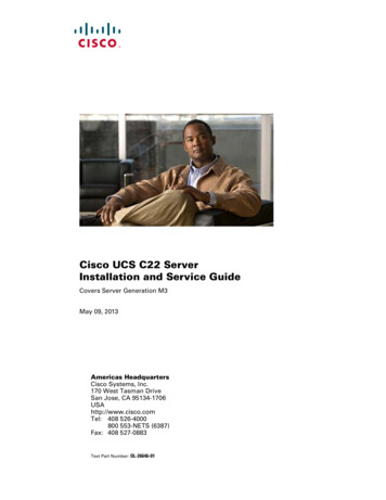
Chapter 1CPS OperationsPolicy Server Deployment Start to Finish OVF Template DeploymentVMware vSphere Hypervisor Install and ConfigurationInstall VMware ESXi 4.1 Step 1Download and request a free license from VMware at:http://www.vmware.com/go/get-free-esxiFor further clarification, refer to the VMware vSphere Hypervisor Install Guide at:http://www.vmware.com/pdf/vsphere4/r41/vsp 41 esxi i vc setup guide.pdfStep 2Burn the ISO to a disk.Step 3Boot your server off of the ISO disk.Please refer to your server’s owners manual for directions on how to change the boot order.Step 4Run the installer and accept all the defaults.Configure VMware ESXi 4.1 Step 1Connect a keyboard and monitor to your newly installed ESXi server.Step 2Press F2 to customize the system.Cisco Policy Suite 6.1 Operations Guide1-15
Chapter 1CPS OperationsPolicy Server Deployment Start to FinishStep 3Step 4When prompted for a user name and password: Type root as the user name. Leave the password blank. Press OK.Select Configure Password from the System Customization menu to configure the password to broadhop.The Old Password is blank.Step 5For the New Password and Confirm Password, type broadhop.Cisco Policy Suite 6.1 Operations Guide1-16
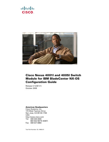
Chapter 1CPS OperationsPolicy Server Deployment Start to FinishStep 6Configure the network interface to which you will connect your ESXi client.Step 7Select Configure Management Network from the System Configuration menu.Step 8Make sure you select the correct Network Adapter on which your management interface will reside.Cisco Policy Suite 6.1 Operations Guide1-17
Chapter 1Policy Server Deployment Start to FinishIn this example, there are only two network interfaces.Define the first physical network interface as the management interface.Step 9Highlight the physical interface you wish to use and select it with the spacebar.Step 10Optional: If there is a flat network there is no need to configure a VLAN.To configure a VLAN, select VLAN from the Configure Management Network menu.Cisco Policy Suite 6.1 Operations Guide1-18CPS Operations
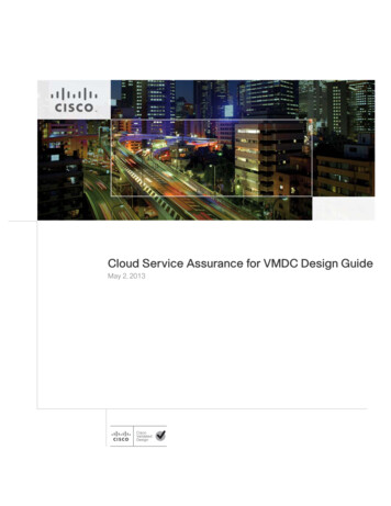
Chapter 1CPS OperationsPolicy Server Deployment Start to FinishFor this example the ESXi host's management interface is on vlan 172.Step 11Type your own interface ID and press Enter.Step 12Setup the IP address for the ESXi server. Select IP Configuration from the Configure ManagementNetwork.Cisco Policy Suite 6.1 Operations Guide1-19
Chapter 1CPS OperationsPolicy Server Deployment Start to FinishStep 13On the IP Configuration screen, make sure Set static IP address and network configuration is selected,then fill out the IP address, subnet mask, and gateway information.Step 14Select yes or OK to restart the network management agents.Test your management network and make sure you can ping the default gateway.Cisco Policy Suite 6.1 Operations Guide1-20
Chapter 1CPS OperationsPolicy Server Deployment Start to FinishStep 15Select “Test Management Network” from the configuration screen.Step 16Enter the gateway IP address and press OK.The reply should come back OK.Step 17If you get a ping reply, then continue on to OVF Template Deployment.Cisco Policy Suite 6.1 Operations Guide1-21
Chapter 1CPS OperationsPolicy Server Deployment Start to FinishOVF Template DeploymentThis section helps you deploy or install the OVF templates required to run the virtual machines at yoursite. Install vSphere Client OVF Template Location Import OVF TemplatesInstall vSphere ClientStep 1When your ESXi server is connected to your network, open a browser and point to the IP address of yourESXi server:https://esxi ip address here/Step 2Click on the “Download vSphere Client” link.Step 3Run the installer and accept the defaults.OVF Template LocationTo obtain the OVF templates, contact your Cisco technical staff. These templates are kept inside theCisco firewall on Confluence for security and ease of update.Import OVF TemplatesStep 1Start your vSphere Client.Cisco Policy Suite 6.1 Operations Guide1-22
Chapter 1CPS OperationsPolicy Server Deployment Start to FinishStep 2Enter the IP address of your vSphere Hypervisor Server along with the user name and password.Step 3When authenticated, select File Deploy OVF Template.Step 4Select the location of the OVF Template on your local machine.Step 5Press Next to verify the details of the OVF Template.Cisco Policy Suite 6.1 Operations Guide1-23
Chapter 1CPS OperationsPolicy Server Deployment Start to FinishStep 6Press Next to ent
Contents iv Cisco Policy Suite 6.1 Operations Guide VMware vSphere Hypervisor Install and Configuration 1-15 Install VMware ESXi 4.1 1-15 Configure VMware ESXi 4.1 1-15 OVF Template Deployment 1-22 Install vSphere Client 1-22 OVF Template Location 1-22 Import OVF Templates 1-22 Console Management 1-26 Unified API Security: Access Privileges 1-30