Transcription
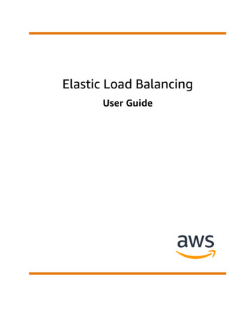
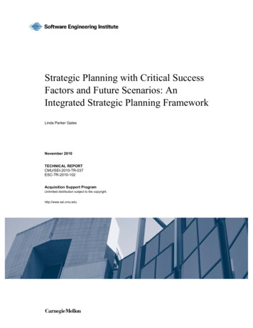
Rev. Roum. Sci. Techn.– Électrotechn. et Énerg.Vol. 63, 2, pp. 202–209, Bucarest, 2018Dedicated to the memory of Academician Andrei ŢuguleaPROPOSED SCENARIOS OF THE LOAD BALANCING MECHANISMIN MULTIPROTOCOL LABEL SWITCHING NETWORKSEMA-MARIA GALEȘ1, VICTOR CROITORU1, MARIUS IORDACHE2Key words: Algorithm, Multiprotocol label switching (MPLS), Load balancing, Tunnel, Virtual private network (VPN),Multiprotocol-border gateway protocol (MP-BGP), Label.The present paper emphasizes the crucial benefits of Internet protocol/multiprotocol label switching (IP/MPLS) networks. Thisprotocol implies broad development of the information transmission between users and successful implementation of algorithmsand methods that might generate a balance in the data load passing through the links between devices. MPLS proposesimperative solutions to network architectures that are affected by rapid changes of the properties of traffic, such as traffic peaksthat must be controlled. Additionally, this document underlines the efficiencies of MPLS networks such as lower costs, quality ofservice attributes, scalability and vigorous traffic routing by creating two scenarios and analyzing their characteristics.1. INTRODUCTIONAs the networking domain has rapidly evolved during thelast years, the need for dynamism in a communication systemis crucial. Time, costs, efficiency and reliability are valuableaspects that are to be taken into consideration when deliveringvarious services to the customers, from the point of view ofa service provider. Consequently, there is a small number ofpossibilities regarding the manner in which the informationof any type is transmitted through the networks [1].The solution is represented by multiprotocol labelswitching (MPLS), which is increasingly used in the recentnetworks, because it greatly differs from the common IProuting by many particular features. In the Internet Protocol(IP) world, many aspects of MPLS are seen as foreign,because of the fact that they can be considered extremelycomplicated or they can be mistakenly presented. Even ifthere are imple-mentations that utilize only basic characteristicsof MPLS, it is still a very powerful tool that greatlyinfluences any network [1].MPLS is increasingly used in the recent networks,because it greatly differs from the common IP routing bymany particular features. In the IP world, many aspects ofMPLS are seen as strange, because of the fact that they canbe considered extremely complicated or they can bemistakenly presented. Even if there are implementationsthat utilize only basic characteristics of MPLS, it is still avery powerful tool that greatly influences any network [1].2.1. EVOLUTIONMPLS is found somewhere between the data link layerand the network layer and it supports end-to-end circuitsover any type of transport medium, using any network layerprotocol. It combines the performance and simplicity ofLayer 2 with the flexibility and scalability of Layer 3 [2].The main advantage is the transmission based on labelingthe ingress packets based on their destination address or apreconfigured criteria and the switching of the traffic over acommon infrastructure. MPLS gives the possibility oftransporting IP version 4 (IPv4), IPv6, Ethernet, Point toPoint Protocol (PPP) and other Layer 2 technologies over it.2. IP/MPLS NETWORKSFirst of all, it does not use IP addresses to route thetraffic, but some labels that have local meaning (betweentwo routers). Secondly, it enables the mapping of real-timeinformation (voice, video) to links that have a low latency,which is difficult in the case of IP routing. Thirdly, thecircuit-based forwarding is easily replaced by packet-basedstructures. Figure 1 presents the placement of MPLS in theopen systems interconnection (OSI) stack.Fig. 1 – The position of MPLS in the OSI model.12.2. MPLS ARCHITECTUREThe MPLS networks are built in order to connect differentlocal area networks (LANs), by use of some equipment thathave specific roles. In order to understand how MPLSworks, one has to study the MPLS labels and their rolewhen attached to the packet in the traffic forwarding. TheMPLS header has the structure of 32 bits (4 bytes), dividedinto 4 sections. The label stack may have one or morelabels in its structure, depending on the MPLS applications(MPLS virtual private network (VPN) and Any Transportover MPLS (AToM) need two labels in the stack). The firstlabel is the top label and the last one is the bottom label.The number of labels between these two can be countless.The bottom of stack (BoS) for all the labels except thebottom label is set to 0. The MPLS label stack is positionedbefore the Layer 3 packet, precisely the header of thetransported protocol and after the Layer 2 header [1].Figure 2 presents a possible architecture of an MPLSnetwork, including the most important constitutive elements.“Politehnica” University of Bucharest, Faculty of Electronics, Telecommunications and Technology of Information, Romania,E-mail: gales.ema@gmail.com, croitoru@adcomm.pub.ro2Orange Romania, E-mail: marius.iordache@orange.com
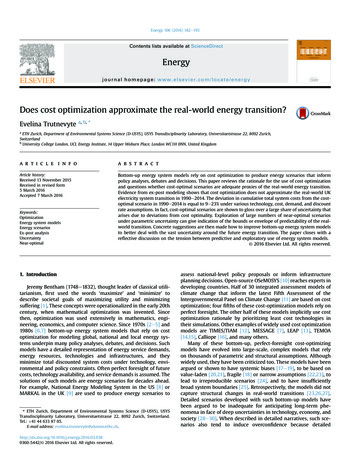
2Load balancing multiprotocol label switching networks-scenarios2033. THE LOAD BALANCING MECHANISMFig.2 – MPLS network architecture.2.3. MPLS OPERATIONThe label switch routers (LSRs) are the networkingequipment found inside the network and they can also becalled transit LSRs and they split into:a) Ingress LSRs, which receive packets that are notlabeled and insert a label/a label stack in front of them,sending afterwards the packets on a data link.b) Egress LSRs, which receive labeled packets andremove the label(s), sending them afterwards on a data link.Ingress and egress LSRs are also named edge LSRs,because they are situated at the edge of an MPLS network.c) Intermediate LSRs, which receive a labeled packet andafterwards they make an operation on it, they switch it andsend the packet on the corresponding data link.A LSR is capable of performing 3 operations: pop, pushor swap. The label switch path (LSP) is a sequence of LSRsthat switch a labeled packet through an MPLS network orjust through a part of it, meaning that it is actually the paththat packets take when forwarded through an MPLS network.A LSP begins with ingress LSR and ends with an egressLSR, both connected further to customer edge (CE) routers [2].Figure 3 is an example of the operation of MPLS in anetwork, with labels specific to each pair of neighboringrouters and the connections between them.Label distribution protocol (LDP) is based on the followingmechanism: every interior gateway protocol (IGP) IP prefixin the routing table has its specific local binding, meaningthat the IPv4 prefix has a label attached to it. These bindingsbecome remote bindings when they are split among theLSRs which become LDP neighbors. They store theseremote and local bindings in a table called label informationbase (LIB). Usually, the remote bindings are more than one,because the LSR has more than one adjacent LSR [2].Fig. 3 – IPv4-over-MPLS network running LDP.Traffic engineering (TE) is defined by all the techniquesapplied to a network in order for it to function properly andbe optimized when necessary. The optimization is realizedby redirecting the traffic to those lightly loaded paths suchthat the load among the paths to be balanced as per thediverse metrics calculated. The purpose of doing this is toavoid the congestion across the network and this fact leadsto a competition between the Internet service providers(ISPs) in order to provide quality of service (QoS) [3].There are two principal methods of balancing the traffic:per-destination and per-packet. By default, the load-sharingof type per-destination is configured on a device and itactually implies the hashing algorithm of the source anddestination IP addresses. Also, it can be related to “perflow” load-balancing, because it sends packets of the samedestination on the same link, this way assuring an orderedstream at the final destination [4].In order to do the load balancing for the labeled packets,the paths that are unlabeled (IP) are not considered, if thereare also labeled paths for the same prefix. It happensbecause the possibility might exist to lose the traffic flowgoing over the unlabeled path. When considering MPLSimplemented on an IPv4 network, the packets succeed inreaching the destination even without labels attached tothem. At the links where MPLS is not enabled, the packetsbecome unlabeled and reach their state of being labeledagain at the next link where MPLS is implemented. Whenbecoming unlabeled, there is an IP lookup in those packetsand because there is IPv4 running everywhere, the deliveryof the unlabeled packet to the destination without problemsshould successfully happen. In contrast, in MPLS VPN orAToM, the packet that is unlabeled at a certain momentdoes not reach the final destination [5].3.1. LAYER 2 LOAD BALANCINGLoad-balancing at Layer 2 uses EtherChannel, meaningthat the traffic is balanced across all the links in theEtherChannel. It transforms the bits from the addresses inthe frame into a digit used to choose one of the links in theEtherChannel. It is usually used to interconnect LAN switches,routers, servers and customers. EtherChannel includes fastEtherChannel, Gigabit EtherChannel, port channel and portgroup [6].The distribution of the data load in the channel is donebased on a hash. Port aggregation control protocol (PAgP)automatically builds the links in the EtherChannel, bysending specific packets that negotiate the characteristics ofthe channel. The constraints imposed by PAgP refer,generally, to the fact that all the configured ports must be inthe same virtual LAN (VLAN) or defined as trunk ports,they must also run at the same speed and there are only theauto-desirable, desirable-desirable and on-on combinationsof PAgP that permit the construction of a bundle [6].Link aggregation control protocol (LACP) is an alternativeto PAgP. The LACP packets are sent only between activeactive or active-passive ports. LACP does not interoperatewith PAgP, all ports that are implied in the process ofbuilding a channel being obliged to run one of them [6].At layer 2, load-balancing is done on the basis of thesource and destination media access control (MAC) addresses.
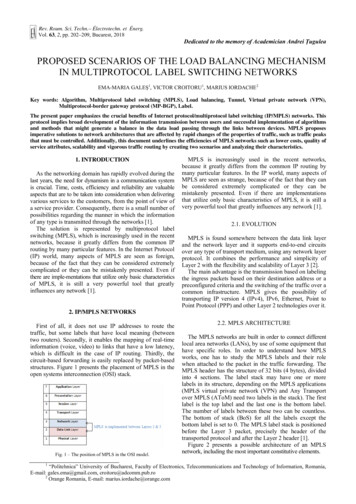
3Ema-Maria Galeș, Victor Croitoru, Marius IordacheBasically, the EtherChannel load-balancing algorithm isbased on the exclusive (ORXOR) operation between thesource and destination addresses. The hashing process cannotbe enabled to load balance the traffic among the ports in anEtherChannel. The hashing mechanism calculates a numberin the interval 0–7 and based on this value, the specific portin the EtherChannel is selected. The most suitable mannerto have a good load-balancing is to set an even number oflinks in EtherChannel, simultaneously controlling the throughputof the link, because if the physical ports are in a numberequal to a power of 2 (2, 4, 8), the traffic is equally balanced.In the case of having a port-channel with 3 interfaces thatare bundled, the load-balancing algorithm needs two bits touse from the hash. Additionally, these two bits result in fourcombinations (00, 01, 10, and 11) connected to the physicalport. In consequence, the data flow is split unequally, notbeing in percentage of 33 % on each channel, but on 50 % onone and 25 % on the other two links [7].3.2. LAYER 3 LOAD BALANCINGA router automatically learns its parallel paths to a certaindestination using a standard routing protocol and balancesthe traffic over these routes according to the routing table.The load-balancing implies the distribution of the trafficacross different links in a channel if considering layer 3(L3) routing details.3.2.1. Layer 3 ECMPEqual-cost multi-path (ECMP) load-balancing representsthe possibility to have links with their own IP address of theinterface with the interior gateway protocol (IGP) configuration,this way obtaining the next-hop routes.This type of load balancing can be made by having eitherL3 information or layer 4 (L4) information (with source anddestination ports). In this manner, the hashing algorithm isprocessed and all the data from the same flow go on thesame route. If there is the case of a flow which needs moreresources, like bandwidth, than another flow, the way ofmaking use of the path can be different and consequently,the data not be equally spread [4].3.2.2. Link BundlingLink bundling refers to the possibility of putting togethera variety of links and transforming them into a single logicallink. The objective is to improve the bidirectional bandwidth,redundancy and to acquire load balancing between two devices(for instance, routers). The bundle implies a virtual interface.Moreover, the components inside it can be dynamicallyadded or deleted from it. This interface can have an IP addressand other abilities, resulting in the fact that the entire dataload sent to the entire bundle is further sent to one of thelinks inside of it [6]. EtherChannel is used to form bundlesof Ethernet interfaces, having no mechanism of checkingwhether the links in the bundle are compatible or not. Loadbalancing can be enabled on all the members of the bundle.It can be done per-destination or per-packet.Figure 4 presents the fact that the load balancing is basedon the decision made at the line card (LC) ingress level.When sending the data flow to a certain LC, path or member,it is surely the one forwarding the traffic further. In theabove figure, there are two paths: the first one is on LC2and the second one is through the bundle, which has twomembers on two LCs [7].Fig.4 – Architecture of L3 load balancing.The traffic is forwarded based on the decision of theingress network processing unit (NPU) on the LC1, takinginto consideration the hash computation. If it indicatesPATH1 to transmit the data flow, then LC1 only sends it toLC2. If it shows the second path (the bundle-ether) toforward the traffic, then the link aggregation (LAG) selectsjust that specific member of the bundle and sends it to theNPU of the LC of that certain member that is going totransmit the traffic [7].In addition, the multiple ports inside the link bundlebehave as one link and present the great advantage that theymight extent to various line cards to build only one interface,the damage of a link having no influence on the rest ofthem. A crucial benefit is constituted of the fact that the trafficis split over all available components of the link bundle.The members of the link bundle are essentially of the sametype and have the same speed.The load balancing of type “per-destination” allocates thepackets on one of the members in the link bundle with thepurpose of having the load balanced, taking into considerationthe hashing algorithm, precisely the hash previously calculatedusing the source and the destination addresses together withuser routing information. Consequently, all the traffic thathas to go to a certain destination from a specific sourcegoes on the same link [7].3.2.3. Bundle in layer 2 and layer 3 scenariosWe can take into consideration the distinctive structuresof the link bundle, depending on the layers at which it isimplemented. Therefore, the hash is computed in a differentmanner. In the situation of having an IP address configuredon the interface of the link bundle, ECMP load sharing canbe applied. In the situation of having an attachment circuit(AC), it is necessary to perform L2 (Layer 2) loadbalancing, being based on the source and destination MAC(Media Access Control) addresses of the devices and on therouter-IDs (identification). In the case of having two routerson each edge of the AC, the MAC addresses are notchangeable, resulting in the fact that L3 load balancingmight be implemented on the L2-based VPN structure [8].Figure 5 underlines three use case scenarios. In the firstcase, there is a link bundle AC, having configured thetransport of L2 and the VPN at L2. The second situationemphasizes having a pseudo-wire (PW) over the interfaceof the bundle-ether, case where the AC has no significantfunction, because it includes MPLS load sharing togetherwith L2 VPN and IP addresses. The third case underlines
4Load balancing multiprotocol label switching networks-scenariosthe presence of a bundle-ether, where the routing process ismade by the LAG. Here the header of the bundle-ether isaccompanied by the header of MPLS and both lead furtherby the IP header, resulting in the chance of implementingload sharing of L3 [8].2054. IMPLEMENTATION OF A LAYER 3IP/MPLS NETWORKMPLS comes with an important benefit, namely the factthat it respects the label switching based on exact matchingof the lookups, which is cheap, easy to use and noticeablydecreases the load on the core routers. Other crucial aspectsof MPLS are represented by the possibility of controllingthe data flow through the network and of prioritizing adiversity of services while preventing congestion, byimplementing TE [10].4.1. MPLS VPNv4Fig.5 – L2/L3 load balancing use case scenarios [12].When implementing L3 load-balancing, there are somespecial configurations and restrictions that must be takeninto account. Otherwise, problems like the automatic disablingof the EtherChannel interfaces may appear, in order toavoid loops in the network. So, in the case of EtherChannelconfiguration, the following steps must be taken into account:there can be a maximum number of eight physical ports ona module and they have to support EtherChannels; all LANports must use the same protocol (PAgP, LACP), becausethere is no possibility to have two EtherChannel protocolsin one EtherChannel; all the ports have to be of the samespeed and in the same duplex mode; no LAN port must beshut down in an EtherChannel, in order to have no linkfailures and avoid the necessity to transfer the data flow tothe other available port in the EtherChannel; no EtherChannelwould be built if having one of the ports as a destinationport; there must be L3 addresses assigned to the portchannel logic interface and not to the physical ports [8].3.2.4. MPLS VPN load balancingThe MPLS VPN is an implementation of MPLS that hasrecently gained a lot of popularity because of its importantcharacteristics such as scalability and the ability to separatethe network into smaller ones, a benefic aspect of a largeenterprise network. MPLS VPN is used for transmission atL2 or L3 and the network structure is extremely importantin the traffic load balancing [9].The load balancing algorithms implemented at the VPNlevel might be diverse, depending on the way the links tothe tunnels are organized. When considering L2 VPNs, theEthernet frames are transmitted in a manner very similar tothe transmission between two physical devices such asswitches in different buildings [9]. In the case of L3 VPNs,the two ends of the constructed tunnel over VPN are situatedon two different subnets, having different IP addresses andtransporting IP packets across the VPN.Furthermore, to load share the data, LACP can be used inorder to add various links together or both ECMP and IGPconfiguration in order to have the routes associated to differentnext-hops and not to a single one. There is the possibility totake into consideration the bandwidth of the routes andreserve it for distinct purposes of the traffic flows, but alsoto not pay attention to the bandwidth [9].We bring in multiprotocol-border gateway protocol (MPBGP) and peer-to-peer VPN. These protocols imply theexistence of a route reflector (RR) as well as VRF (VPNrouting/forwarding). We created a scenario which outlinesthe likelihood of a L3 MPLS-based VPN to access theInternet. The practical usage is to support the VPNconnectivity between corporate sites. VPNs serve as a methodto share bandwidth between customers using an Internetservice provider (ISP) network as a backbone. A VPNmight also be seen as an association of sites that have acommon routing table. The customer routers are connectedby one or more interfaces to the service provider (SP) routers,that link, in turn, every interface to a VPN. The VRF isbasically the routing table of a VPN [11].More than one VPN can be enabled on a service providerrouter and the device can effectively make the differencebetween their links. Also, the router is the point where thebonding between the various VRFs and the specific L3interfaces is made, because a L3 interface must correspondto a single VRF. The locally known routes are advertised bythe CE routers to the provider edge (PE) routers and in turnthey find out the remote routes that take part in the VPNprocess from the PEs. The VPN paths for the SP are not allincluded into the configuration of the PEs, those that aredirectly linked to it being an exception. internal bordergateway protocol (iBGP) announces between PEs the VPNsthat are advertised by CEs to PEs, taking into account thatPEs have each VRF corresponding to each connected site.In fact, we use multiprotocol-border gateway protocol (MPBGP ), which enables IPv4 unicast addresses and transmitsthe VPN labels into the MPLS VPNs [12].VPNs of version 4 can be considered, taking into accountthat the CE routers are announcing their routes to PE routersusing dynamic routing protocols, such as OSPF (open shortestpath first). The PEs in turn connect to CEs by two VPNs(customer1 and customer2), enabling the address-family IPv4unicast VRFs. Consequently, every VPN existing betweenthem has its own VRF that additionally has its paths insideof it. The two PEs have a VPNv4 connection between themcompared to the provider (P) routers that are placed in thecentral network and run MPLS. So PEs announce to eachother the links included in the VRFs, paths that are actuallyVPNv4 routes with route targets (RT), RD (routedistinguisher) and a VPN label. This way the MPLS L3VPNs are built. IPv4 routing represents the base of the twocustomers’ communication, whereas inside the corenetwork, iBGP is used to advertise the collected paths fromthe VPNs between PEs [12].
5Ema-Maria Galeș, Victor Croitoru, Marius IordacheConcisely, the IPv4 address-family is utilized to revealthe simple IPv4 addresses and the VPNv4 address-familyputs the 64 bits of the RD into them, in this manner formingexclusive VRFs. The RT describes the structure of thenetwork of the VPNv4 and the label of the VPN, whichmakes the PEs able to know each VPN marked by the dataload flowing into them [12].4.2. ROUTE REFLECTORAs long as routing loops in a network are concerned,BGP is a powerful tool to warn them, based on the principlethat the routes learned from an iBGP peer are notannounced to the other iBGP neighbors. This methodrequires a logical full mesh topology in order to permit thetransmission of the traffic in the entire network, but this isnot a solution for the scalability of it, particularly inextensive structures. Consequently, a convenient idea is thatof the use of a route reflector in the process of BGP [13].A BGP route reflector is simultaneously the point ofconcentration (central point/server) in the network and therouter that advertises the paths received from an MP-BGPpeer to other MP-BGP peers, respecting certain constraints.This way, it ensures the extensibility of the network,making it possible for the BGP routers in the topology toconnect only to the RR and not necessarily to all the otherrouters in a full mesh model. The routers peered with theroute reflector are called route reflector clients and theyindividually need to be configured as such. Moreover, theRR represents a single point of failure, meaning that in caseof damage, the whole circuit of routers is interrupted fromworking. So, in order to provide reliability as well as redundancyin the network, there is recommended to implement asecond RR [13].Another significant role of the RR is underlined by thefact that it avoids the necessity to implement specificsupplementary commands on all the existent PE routerswhen adding new PEs in the service provider system.However, this addition of a PE demands a neighborannouncement on it pointing to the RR and a neighborannouncement referring to the new PE on the RR router [13].A route reflector can have two kinds of peers: routereflector clients and non-clients. The routes from a clientare transmitted to clients, non-clients and external BGP(eBGP) associates, whereas the routes from a non-client arerevealed only to clients and eBGP peers. The RR and itsclients define a cluster, which is characterized by thecluster-id inserted to each path made known by the RR tothe clients and non-clients [13].4.3. LAYER 3 VPNV4 TRAFFIC BALANCINGMECHANISM-PROPOSALWe created a L3 VPNv4 MPLS structure with the purposeof indicating the crucial benefits of MPLS as well as ofVPNs of version 4. This first scenario is formed from eightrouters with various functions in the network. We utilizedUNetLab (Unified Networking Lab), a platform that allowsthe simulation, construction, examination and correction ofboth real and potentially built networks [12].We enabled two VPNs on the two interfaces between R5(Router 5) and R6 (Router 6), correspondingly router 7(R7) and router 8 (R8). This way, we deal with one VRFassigned to customer1 on Ethernet0/0 and one VRF associatedto customer2 on Ethernet0/1. The RD is the object makingthe difference between the two VRFs, which consists of theautonomous system (AS) and a special digit for each ofthem. The two PEs from the topology are found in the sameAS (BGP depends on the AS).As long as OSPF is concerned, it upholds multiple VRFs,meaning that it can block the possible creation of loops inthe network, because it reorganizes the paths between BGPand OSPF. Having this characteristic, the router can be seenas multiple diverse virtual routers that have their ownrouting tables together with VRF tables for the VPNs [14].The two implemented customers are found in two areasof OSPF, because this aspect gives the possibility to thedifferent customers to have their routes completely separated.In this manner, the paths can be seen as VPNs, which is aalso a convenient condition for MPLS [14].Figure 6 is identified with the logical diagram of the firstscenario (created in UNetLab). As is can be seen, it isformed from a core area, with OSPF area 0 set up on therouters and intermediate system-to-intermediate system (ISIS), which helps with the examination of the dynamicrouting protocols. In addition, MPLS is used to highlightthe paths of customer 1 and customer 2 (by the transmissionof labeled packets) and the extremely important role of theRR, which uses MP-BGP to deliver the traffic flowingthrough these two VPNs to the specific clients [12].As long as the core area is concerned, all the pathsbetween the central routers are dynamically routed byOSPF and IS-IS, which have the administrative distance(AD) different. This AD makes the difference between thetwo protocols, because as this number is smaller, the erefore,OSPF represents the one elected in our case, because its ADis equal to 110, whereas IS-IS has the AD exactly 115 [12].We enabled further the fundamental characteristics ofMPLS, this way making an analysis of the transmission ofthe data load through the routes in the network. Thetransportation of the traffic is strongly dependent on thelabels that the router found at the starting point of thenetwork insert on the header of the packets.Figure 7 shows the design of the eight routers used toexamine the load balance of the traffic and they have thefollowing functions:– R1, R2, R3, R4 - P (provider) routers– R5, R7 - PE (provider edge) routers– R6, R8 - CE (customer edge) routers.R1, R2, R3, R4, R5 and R7 (the routers in the middle)have MPLS capacities enabled, while R6 and R8 operate byusing only IP addresses. CEs link straight to PEs and theydo not know about the VPNs, because only the PEs dealwith the forwarding of the MPLS packets. P routers serveas the backbone routers in the SP structure [12].The PEs are fed with the routing information by R6 andR8 that make use of OSPF, which supports multi-instance.Between the ingress LSR and the egress one, meaning R5and R7, the routing data is learned through MP-BGP andthe use of MPLS labels as shown in Fig. 7.R6 is recognized as CE1 (Site 1) and we mightacknowledge that if it sends an IPv4 packet with thedestination address 62.0.0.8 (loopback0 address of R8),which is recognized as CE2 (site 2), R6 performs an IPlookup in the routing table and sends further the traffic toR5 (PE1) in the suitable way. R5, which is the ingress LSRin the topology, inserts the MPLS label into the packet and
6Load balancing multiprotocol label switching networks-scenariosmakes the decision based on which the next-hop BGProuter would be (PE2) [12].After all, R5 sends the MPLS packets to the first P in thetopology (R3 or R4) and the packets then follow thecalculated route to the final target point.Fig. 6 – The logical scheme of a L3 MPLS VPNv4-based topology [12].Fig. 7 – L3 MPLS VPNv4-based practical topology [12].207R5 makes the load sharing of the data on these two links(the two routes going to PE2). Each P router on a certainLSP sends the traffic to the penultimate-hop router, R1 orR2, making use of the labels. The function of R1 and R2 isto pick up the interface that leads to PE2 and to pop theMPLS label, process that is called penultimate hop popping(PHP). This process leads further to the transmission of thepackets to the final point in the network. CE2 receives theIPv4 packets from PE2 that makes an IP lookup in therouting table [15].Taking into consideration the fact that the two enabledVPNs need two areas of OPSF, R6 and R8 have twoloopback addresses (loopback0 and loopback1), whereas allthe other routing devices in the entire network have onlyloopback0 enabled. We set up OSPF and IS-IS in thenetwork and on the PEs, as previously mentioned, weimplemented BGP and MPLS, including LDP. BGP makesuse of the loopback addresses on R5 and R7. Theseaddresses are important, because of the fact that they are‘a
Basically, the EtherChannel load-balancing algorithm is based on the exclusive (ORXOR) operation between the source and destination addresses. The hashing process cannot be enabled to load balance the traffic among the ports in an EtherChannel. The hashing mechanism calculates a number in the interval 0-7 and based on this value, the specific .