Transcription
BLADE OS 21.0Application GuideBNT Layer 2-7 GbE Switch Module for IBM BladeCenter Version 21.0Part Number: 24R9742, March 20062350 Mission College Blvd.Suite 600Santa Clara, CA 95054www.bladenetwork.net
Layer 2-7 GbE Switch Module Application GuideCopyright 2009 Blade Network Technologies, Inc., 4655 Great America Parkway, Santa Clara, California95054, USA. All rights reserved. Part Number: 24R9742This document is protected by copyright and distributed under licenses restricting its use, copying,distribution, and decompilation. No part of this document may be reproduced in any form by any meanswithout prior written authorization of Blade Network Technologies, Inc. Documentation is provided “asis” without warranty of any kind, either express or implied, including any kind of implied or expresswarranty of non-infringement or the implied warranties of merchantability or fitness for a particularpurpose.U.S. Government End Users: This document is provided with a “commercial item” as defined by FAR2.101 (Oct. 1995) and contains “commercial technical data” and “commercial software documentation” asthose terms are used in FAR 12.211-12.212 (Oct. 1995). Government End Users are authorized to use thisdocumentation only in accordance with those rights and restrictions set forth herein, consistent with FAR12.211- 12.212 (Oct. 1995), DFARS 227.7202 (JUN 1995) and DFARS 252.227-7015 (Nov. 1995).Blade Network Technologies, Inc. reserves the right to change any products described herein at any time,and without notice. Blade Network Technologies, Inc. assumes no responsibility or liability arising fromthe use of products described herein, except as expressly agreed to in writing by Blade NetworkTechnologies, Inc. The use and purchase of this product does not convey a license under any patent rights,trademark rights, or any other intellectual property rights of Blade Network Technologies, Inc.BLADE OS is a trademark of Blade Network Technologies, Inc. in the United States and certain othercountries. Cisco and EtherChannel are registered trademarks of Cisco Systems, Inc. in the United Statesand certain other countries. Check Point and FireWall-1 are trademarks or registered trademarks ofCheck Point Software Technologies Ltd. Any other trademarks appearing in this manual are owned bytheir respective companies.Originated in the U.S.A.224R9742, March 2006
ContentsPreface 19Who Should Use This Guide 19What You’ll Find in This Guide 19Typographic Conventions 21How to Get Help 22Part 1: Basic Switching 23Chapter 1: Accessing the Switch 25Management module setup 26Factory-Default vs. MM assigned IP Addresses 26Default Gateway 27Configure management module for switch access 27Using Telnet 29Connect to the Switch via SSH 30BOOTP Relay Agent 30Using the Browser-Based Interface 31Configuring BBI Access via HTTP 32Configuring BBI Access via HTTPS 33Using SNMP 34Using the Console Port 35Securing Access to the Switch 36Setting Allowable Source IP Address Ranges 37RADIUS Authentication and Authorization 38TACACS Authentication 42Secure Shell and Secure Copy 4824R9742, March 20063
Layer 2-7 GbE Switch Module Application GuideEnd User Access Control 55Considerations for Configuring End User Accounts 55Strong Passwords 56User Access Control Menu 56Listing Current Users 58Logging into an End User Account 58Chapter 2: VLANs 59Overview 60VLANs and Port VLAN ID Numbers 60VLAN Numbers 60PVID Numbers 61VLAN Tagging 62VLAN Topologies and Design Considerations 66VLAN configuration rules 67Example 1: Multiple VLANs with Tagging Adapters 67VLANs and Default Gateways 69Segregating VLAN Traffic 69Configuring the Local Network 71Configuring Gateways per VLAN 71Chapter 3: Ports and Trunking 75Overview 76Statistical Load Distribution 77Built-In Fault Tolerance 77Before you configure static trunks 77Trunk group configuration rules 78Port Trunking Example 79Configurable Trunk Hash Algorithm 81Link Aggregation Control Protocol 82Configuring LACP 84Chapter 4: Spanning Tree Group 85Overview 86Bridge Protocol Data Units (BPDUs) 87Determining the Path for Forwarding BPDUs 87Spanning Tree Group configuration guidelines 884 Contents24R9742, March 2006
Layer 2-7 GbE Switch Module Application GuideMultiple Spanning Trees 90Default Spanning Tree configuration 90Why Do We Need Multiple Spanning Trees? 91Switch-Centric Spanning Tree Group 91VLAN Participation in Spanning Tree Groups 92Configuring Multiple Spanning Tree Groups 93Port Fast Forwarding 94Configuring Port Fast Forwarding 94Fast Uplink Convergence 95Configuration Guidelines 95Configuring Fast Uplink Convergence 95Part 2: IP Routing 97Chapter 5: Basic IP Routing 99IP Routing Benefits 100Routing Between IP Subnets 100Example of Subnet Routing 103Defining IP Address Ranges for the Local Route Cache 107Configuring Static Multicast Routes 108Dynamic Host Configuration Protocol 108DHCP Relay Agent 109DHCP Relay Agent Configuration 110Chapter 6: Routing Information Protocol 111Distance Vector Protocol 111Stability 111Routing Updates 112Chapter 7: IGMP Snooping 113Overview 114FastLeave 115IGMP Filtering 115Static Multicast Router 116IGMP Snooping Configuration Example 11724R9742, March 2006Contents 5
Layer 2-7 GbE Switch Module Application GuideChapter 8: Border Gateway Protocol 121Internal Routing Versus External Routing 122Forming BGP Peer Routers 123What is a Route Map? 123Incoming and Outgoing Route Maps 124Precedence 125Configuration Overview 125Aggregating Routes 127Redistributing Routes 127BGP Attributes 128Local Preference Attribute 128Metric (Multi-Exit Discriminator) Attribute 128Selecting Route Paths in BGP 129BGP Failover Configuration 130Default Redistribution and Route Aggregation Example 133Chapter 9: OSPF 135OSPF Overview 136Equal Cost Multipath Routing Support 136Types of OSPF Areas 136Types of OSPF Routing Devices 138Neighbors and Adjacencies 139The Link-State Database 139The Shortest Path First Tree 140Internal Versus External Routing 140OSPF Implementation in BLADE OS 141Configurable Parameters 141Defining Areas 142Interface Cost 144Electing the Designated Router and Backup 144Summarizing Routes 144Default Routes 145Virtual Links 146Router ID 147Authentication 147Host Routes for Load Balancing 150OSPF Features Not Supported in This Release 1516 Contents24R9742, March 2006
Layer 2-7 GbE Switch Module Application GuideOSPF Configuration Examples 151Example 1: Simple OSPF Domain 152Example 2: Virtual Links 154Example 3: Summarizing Routes 158Example 4: Host Routes 161Verifying OSPF Configuration 167Part 3: Application Switching Fundamentals 169Chapter 10: Server Load Balancing 171Understanding Server Load Balancing 172Identifying Your Network Needs 172How Server Load Balancing Works 173Implementing Basic Server Load Balancing 175Network Topology Requirements 176Configuring Server Load Balancing 177Additional Server Load Balancing Options 182Extending SLB Topologies 190Proxy IP Addresses 190Mapping Ports 193Direct Server Interaction 196Delayed Binding 200Session Initiation Protocol Server Load Balancing 203SIP Processing on the Switch 203Configuring SIP Server Load Balancing 204Workload Manager Support 207Chapter 11: Global Server Load Balancing 209DSSP version 1 vs. version 2 209GSLB Overview 210Benefits 210How GSLB Works 211GSLB Enhancements 213GSLB Metrics 213Metric preferences 216Rules 21624R9742, March 2006Contents 7
Layer 2-7 GbE Switch Module Application GuideConfiguring Basic GSLB 217Basic GSLB Requirements 218Example GSLB Topology 218Configuring a Standalone GSLB Domain 231GSLB Topology with a Standalone GSLB Site 231Configuring GSLB with Rules 235Configuring Time-Based Rules 236Using the Availability Metric in a Rule 238Configuring GSLB Network Preference 239Configuring GSLB with Proxy IP for Non-HTTP Redirects 242How Proxy IP Works 244Configuring Proxy IP Addresses 245GSLB DNS Persistence 246Using Border Gateway Protocol for GSLB 246Verifying GSLB Operation 247Chapter 12: Filtering 249Overview 250Filtering Benefits 250Filtering Criteria 250Filtering Actions 252Stacking Filters 252Overlapping Filters 253The Default Filter 253VLAN-based Filtering 255Optimizing Filter Performance 257Filter Logs 257IP Address Ranges 259Cache-Enabled versus Cache-Disabled Filters 259TCP Rate Limiting 260Configuring TCP Rate Limiting Filters 261Tunable Hash for Filter Redirection 265Filter-based Security 266Network Address Translation 272Static NAT 272Dynamic NAT 275FTP Client NAT 2778 Contents24R9742, March 2006
Layer 2-7 GbE Switch Module Application GuideMatching TCP Flags 279Matching ICMP Message Types 284Chapter 13: Application Redirection 287Overview 288Cache Redirection Environment 288Additional Application Redirection Options 289IP Proxy Addresses for NAT 295Excluding Noncacheable Sites 297Chapter 14: Health Checking 299Real Server Health Checks 301Link Health Checks 302Configuring the Switch for Link Health Checks 302TCP Health Checks 303ICMP Health Checks 303Script-Based Health Checks 304Configuring the Switch for Script-Based Health Checks 304Script Format 305Scripting Guidelines 306Script Configuration Examples 306Application-Specific Health Checks 308HTTP Health Checks 309UDP-Based DNS Health Checks 311FTP Server Health Checks 312POP3 Server Health Checks 313SMTP Server Health Checks 314IMAP Server Health Checks 315NNTP Server Health Checks 316RADIUS Server Health Checks 317HTTPS/SSL Server Health Checks 318WAP Gateway Health Checks 318LDAP Health Checks 321Windows Terminal Server Health Checks 322ARP Health Checks 323Failure Types 324Service Failure 324Server Failure 32424R9742, March 2006Contents 9
Layer 2-7 GbE Switch Module Application GuideChapter 15: High Availability 325Layer 2 Trunk Failover 326VLAN Monitor 326Setting the Failover Limit 327L2 Failover with Other Features 327Configuration Guidelines 327L2 Failover Configurations 328Configuring Trunk Failover 331VRRP Overview 332VRRP Components 332VRRP Operation 335Selecting the Master VRRP Router 335Failover Methods 337Active-Standby Redundancy 338Active-Active Redundancy 339Hot-Standby Redundancy 340BLADE OS extensions to VRRP 343Virtual Server Routers 343Tracking VRRP Router Priority 343Virtual Router Deployment Considerations 346Synchronizing Switch Configurations 346Synchronizing Active/Active Failover 347Assigning VRRP Virtual Router ID 348Configuring the Switch for Tracking 348High Availability Configurations 350Active-Standby Virtual Server Router Configuration 350Active-Active VIR and VSR Overview 352Active-Active Server Load Balancing Configuration 353Hot-Standby Configuration 361Four-switch configuration 368Inter-Chassis Redundancy Link 372Layer 2 Trunk Failover with VRRP 37610 Contents24R9742, March 2006
Layer 2-7 GbE Switch Module Application GuidePart 4: AdvancedSwitching 381Chapter 16: Content Intelligent Switching 383Overview 384Parsing Content 385HTTP Header Inspection 385Buffering Content with Multiple Frames 386Content Intelligent Server Load Balancing 387URL-Based Server Load Balancing 387Virtual Hosting 392Cookie-Based Preferential Load Balancing 395Browser-Smart Load Balancing 398URL Hashing for Server Load Balancing 399Header Hash Load Balancing 401DNS Load Balancing 402Content Intelligent Cache Redirection 405URL-Based Cache Redirection 406HTTP Header-Based Cache Redirection 415Browser-Based Cache Redirection 416URL Hashing for Cache Redirection 417Exclusionary String Matching for Real Servers 421Configuring for Exclusionary URL String Matching 421Regular Expression Matching 423Standard Regular Expression Characters 423Configuring Regular Expressions 424Content Precedence Lookup 425Requirements 426Using the or and and Operators 426Assigning Multiple Strings 427Layer 7 Deny Filters 428Chapter 17: Persistence 431Overview of Persistence 432Using Source IP Address 432Using Cookies 433Using SSL Session ID 43324R9742, March 2006Contents 11
Layer 2-7 GbE Switch Module Application GuideCookie-Based Persistence 434Permanent and Temporary Cookies 435Cookie Formats 435Cookie Properties 436Client Browsers that Do Not Accept Cookies 436Cookie Modes of Operation 437Configuring Cookie-Based Persistence 441Server-Side Multi-Response Cookie Search 447SSL Session ID-Based Persistence 448How SSL Session ID-Based Persistence Works 448Windows Terminal Server Load Balancing and Persistence 450Appendix A: Troubleshooting 453Monitoring Ports 454Port Mirroring behavior 455Configuring Port Mirroring 455Filtering the Session Dump 457Appendix B: Radius Server Configuration Notes 459Glossary 463Index 46712 Contents24R9742, March 2006
FiguresSwitch management on the BladeCenter management module 28BOOTP Relay Agent Configuration 30Default VLAN settings 63Port-based VLAN assignment 64802.1Q tagging (after port-based VLAN assignment) 65802.1Q tag assignment 65802.1Q tagging (after 802.1Q tag assignment) 66Example 1: Multiple VLANs with VLAN-Tagged Gigabit Adapters 67Default Gateways per VLAN 69Port Trunk Group 76Port Trunk Group Configuration Example 79Using Multiple Instances of Spanning Tree Group 91Implementing Multiple Spanning Tree Groups 92The Router Legacy Network 101Switch-Based Routing Topology 102DHCP Relay Agent Configuration 110iBGP and eBGP 122Distributing Network Filters in Access Lists and Route Maps 124BGP Failover Configuration Example 130Route Aggregation and Default Route Redistribution 133OSPF Area Types 137OSPF Domain and an Autonomous System 138Injecting Default Routes 145OSPF Authentication 148A Simple OSPF Domain 152Configuring a Virtual Link 154Summarizing Routes 158Configuring OSPF Host Routes 161Traditional Versus SLB Network Configurations 173Web Hosting Configuration Without SLB 175Web Hosting with SLB Solutions 175Example Network for Client/Server Port Configuration 177Basic Virtual Port to Real Port Mapping Configuration 194Mapped and Nonmapped Server Access 19924R9742, March 200613
Layer 2-7 GbE Switch Module Application GuideDoS SYN Attacks without Delayed Binding 200Repelling DoS SYN Attacks With Delayed Binding 201Session Initiation Protocol Load Balancing 204DNS Resolution with Global Server Load Balancing 211GSLB Topology Example 1 218GSLB Topology Example 2—with Standalone GSLB 231Configuring Client Proximity Table 240HTTP and Non-HTTP Redirects 243POP3 Request Fulfilled via IP Proxy 244Assigning Filters According to Range of Coverage 252Assigning Filters to Overlapping Ranges 253Assigning a Default Filter 253VLAN-based Filtering 255Configuring Clients with Different Rates 261Limiting User Access to Server 264Security Topology Example 266Static Network Address Translation 273Dynamic Network Address Translation 275Active FTP for Dynamic NAT 277TCP ACK Matching Network 280Traditional Network Without Cache Redirection 288Network with Cache Redirection 289Basic Layer 2 Failover 328Two trunks, each in a different Failover Trigger 329Two trunks, one Failover Trigger 330A VRRP Router 334VRRP Router in Active-Standby Configuration 336A Non-VRRP, Hot-standby Configuration 337Active-Standby Redundancy 338Active-Active Redundancy 339Hot-Standby Redundancy 340Active-Standby High-Availability Configuration 350Active-Active High-Availability Configuration 353Hot-Standby Configuration 362Four GbESM Active-Active-Active-Active example 369Active-Active Inter-Chassis Redundancy Link example 373Active-Active Configuration with L2 Trunk Failover 377Content Intelligent Load Balancing Example 384URL-Based Server Load Balancing 388Balancing Nontransparent Caches 399Load Balancing DNS Queries 40214 Figures24R9742, March 2006
Layer 2-7 GbE Switch Module Application GuideURL-Based Cache Redirection 408URL Hashing for Application Redirection 419Content Precedence Lookup Protectors Example 426Content Precedence Lookup Multiple Strings Example 427Configuring Layer 7 Deny Filter 429Cookie-Based Persistence: How It Works 434Insert Cookie Mode 438Passive Cookie Mode 439Rewrite Cookie Mode 440SSL Session ID-Based Persistence 44924R9742, March 2006Figures 15
Layer 2-7 GbE Switch Module Application Guide16 Figures24R9742, March 2006
TablesGbESM IP addresses, based on switch-module bay numbers 26User Access Levels 41BLADE OS-proprietary Attributes for Radius 42Default TACACS Authorization Levels 44Alternate TACACS Authorization Levels 44Route Cache Example 70Actor vs. Partner LACP configuration 83Ports, Trunk Groups, and VLANs 86Ports, Trunk Groups, and VLANs 90Subnet Routing Example: IP Address Assignments 103Subnet Routing Example: IP Interface Assignments 103Subnet Routing Example: Optional VLAN Ports 105Local Routing Cache Address Ranges 107Web Host Example: Real Server IP Addresses 178Web Host Example: Port Usage 180Well-Known Application Ports 182Proxy IP addresses on GbE Switch Module 191Proxy Example: Port Usage 192GSLB Example: San Jose Real Server IP Addresses 221GSLB Example: San Jose GbESM Port Usage 222Denver Real Server IP Addresses 227Web Host Example: Port Usage 228HTTP Versus Non-HTTP Redirects 243Well-Known Protocol Types 251Filtering IP Address Ranges 259Web Cache Example: Real Server IP Addresses 267TCP Flags 279ICMP Message Types 284Cache Redirection Example: Real Server IP Addresses 290Active-Standby Configuration 336VRRP Tracking Parameters 344Standard Regular Expression Special Characters 423Real Server Content 428Comparison Among the Three Cookie Modes 43724R9742, March 200617
Layer 2-7 GbE Switch Module Application Guide18 Tables24R9742, March 2006
PrefaceThe BLADE OS 21.0 Application Guide describes how to configure and use the BLADE OSsoftware on the Layer 2-7 GbE Switch Module for IBM BladeCenter. For documentation oninstalling the switch physically, see the Installation Guide for your GbE Switch Module(GbESM).Who Should Use This GuideThis Application Guide is intended for network installers and system administrators engaged inconfiguring and maintaining a network. The administrator should be familiar with Ethernetconcepts, IP addressing, Spanning Tree Protocol, and SNMP configuration parameters.What You’ll Find in This GuideThis guide will help you plan, implement, and administer BLADE OS software. Where possible, each section provides feature overviews, usage examples, and configuration instructions.Part 1: Basic Switching Chapter 1, “Accessing the Switch,” describes how to access the GbE Switch Module toconfigure, view information and run statistics on the switch. This chapter also discussesdifferent methods to manage the switch for remote administrators using specific IPaddresses, RADIUS authentication, Secure Shell (SSH), and Secure Copy (SCP). Chapter 2, “VLANs,” describes how to configure Virtual Local Area Networks (VLANs)for creating separate network segments, including how to use VLAN tagging for devicesthat use multiple VLANs. This chapter also describes how Jumbo frames can be used toease server processing overhead. Chapter 3, “Ports and Trunking,” describes how to group multiple physical ports togetherto aggregate the bandwidth between large-scale network devices. Chapter 4, “Spanning Tree Group,” discusses how Spanning Trees configure the networkso that the switch uses the most efficient path when multiple paths exist.24R9742, March 200619
Layer 2-7 GbE Switch Module Application GuidePart 2: IP Routing Chapter 5, “Basic IP Routing,” describes how to configure the GbE Switch Module for IProuting using IP subnets, and DHCP Relay. Chapter 6, “Routing Information Protocol,” describes how the BLADE OS softwareimplements standard RIP for exchanging TCP/IP route information with other routers. Chapter 7, “IGMP Snooping,” describes how the BLADE OS software implements IGMPSnooping to handle multicast traffic efficiently. Chapter 8, “Border Gateway Protocol,” describes BGP concepts and BGP features supported in BLADE OS. Chapter 9, “OSPF,” describes OSPF concepts, how OSPF is implemented in BLADE OS,and four examples of how to configure your switch for OSPF support.Part 3: Application Switching Fundamentals Chapter 10, “Server Load Balancing,” describes how to configure the GbE Switch Moduleto balance network traffic among a pool of available servers for more efficient, robust, andscalable network services. Chapter 11, “Global Server Load Balancing,” describes configuring Server Load Balancing across multiple geographic sites. Chapter 12, “Filtering,” describes how to configure and optimize network traffic filters forsecurity and Network Address Translation. Chapter 13, “Application Redirection,” describes how to use filters for redirecting trafficto such network streamlining devices as caches. Chapter 14, “Health Checking,” describes how to configure the GbE Switch Module torecognize the availability of the various network resources used with the various load-balancing and application redirection features. Chapter 15, “High Availability,” describes how to use the Virtual Router Redundancy Protocol (VRRP) to ensure that network resources remain available if one GbE Switch Module is removed for service.Part 4: Advanced Switching20 Preface Chapter 16, “Content Intelligent Switching,” describes how to perform load balancing andapplication redirection based on Layer 7 packet content information (such as URL, HTTPHeader, browser type, and cookies). Chapter 17, “Persistence,” describes how to ensure that all connections from a specific client session reach the same server. Persistence can be based on cookies or SSL session ID.24R9742, March 2006
Layer 2-7 GbE Switch Module Application Guide Appendix A, “Troubleshooting,” discusses two tools for troubleshooting your switch—monitoring ports and filtering session dumps. Appendix B, “Radius Server Configuration Notes,” provides an example of RADIUSserver configuration.Typographic ConventionsThe following table describes the typographic styles used in this book.Table 1 Typographic ConventionsTypeface orSymbolMeaningExampleAaBbCc123This type is used for names of commands,files, and directories used within the text.View the readme.txt file.It also depicts on-screen computer output and Main#prompts.AaBbCc123This bold type appears in command examples. It shows text that must be typed inexactly as shown.Main# sys AaBbCc123 This italicized type appears in commandTo establish a Telnet session, enter:examples as a parameter placeholder. Replace host# telnet IP address the indicated text with the appropriate realname or value when using the command. Donot type the brackets.[ ]24R9742, March 2006This also shows book titles, special terms, orwords to be emphasized.Read your User’s Guide thoroughly.Command items shown inside brackets areoptional and can be used or excluded as thesituation demands. Do not type the brackets.host# ls [-a]Preface 21
Layer 2-7 GbE Switch Module Application GuideHow to Get HelpIf you need help, service, or technical assistance, see the "Getting help and technical assistance" appendix in the Layer 2-7 GbE Switch Module for IBM BladeCenter Installation Guideon the IBM BladeCenter Documentation CD.22 Preface24R9742, March 2006
Part 1: Basic SwitchingThis section discusses basic Layer 1-2 switching functions. This includes how to access andmanage the switch: Accessing the switch VLANs Port Trunking Spanning Tree Protocol24R9742, March 200623
Layer 2-7 GbE Switch Module Application Guide24 Part 1: Basic Switching24R9742, March 2006
CHAPTER 1Accessing the SwitchThe BLADE OS software provides means for accessing, configuring, and viewing informationand statistics about the GbE Switch Module. This chapter discusses different methods ofaccessing the switch and ways to secure the switch for remote administrators: “Management module setup” on page 26 “Using Telnet” on page 29 “Using the Browser-Based Interface” on page 31 “Using SNMP” on page 34 “Using the Console Port” on page 35 “Securing Access to the Switch” on page 36 24R9742, March 2006 “Setting Allowable Source IP Address Ranges” on page 37 “RADIUS Authentication and Authorization” on page 38 “TACACS Authentication” on page 42 “Secure Shell and Secure Copy” on page 48“End User Access Control” on page 5525
Layer 2-7 GbE Switch Module Application GuideManagement module setupThe BladeCenter GbE Switch Module is an integral subsystem within the overall BladeCentersystem. The BladeCenter chassis includes a management module as the central element foroverall chassis management and control.You can use the 100-Mbps Ethernet port on the management module to configure and managethe GbE Switch Module. The GbE Switch Module communicates with the management module through its internal port 15 (MGT1) and port 16 (MGT2), which you can access through the100 Mbps Ethernet port on the management module. The factory default settings will only permit management and control access to the switch module through the 10/100 Mbps Ethernetport on the management module. You can use the four external 10/100/1000 Mbps Ethernetports on the switch module for management and control of the switch by selecting this mode asan option through the management module configuration utility program (see the applicableBladeCenter Installation and User’s Guide publications on the IBM BladeCenter Documentation CD for more information).Factory-Default vs. MM assigned IP AddressesEach GbE Switch Module must be assigned its own Internet Protocol address, which is usedfor communication with an SNMP network manager or other transmission control protocol/Internet Protocol (TCP/IP) applications (for example, BootP or TFTP). The factory-default IPaddress is 10.90.90.9x, where x corresponds to the number of the bay into which the GbESwitch Module is installed. For additional information, see the Installation Guide). The management module assigns an IP address of 192.168.70.1xx, where xx corresponds to the numberof the bay into which each GbE Switch Module is installed, as shown in the following table:Table 1-1 GbESM IP addresses, based on switch-module bay numbersBay numberFactory-default IP addressIP address assigned by MMBay 110.90.90.91192.168.70.127Bay 210.90.90.92192.168.70.128Bay 310.90.90.94192.168.70.129Bay 410.90.90.97192.168.70.130NOTE – Switch Modules installed in Bay 1 and Bay 2 connect to server NICs 1 and 2, respectively. However, Windows operating systems show that Switch Modules installed in Bay 3 andBay 4 connect to server NICs 4 and 3, respectively.26 Chapter 1: Accessing the Switch24R9742, March 2006
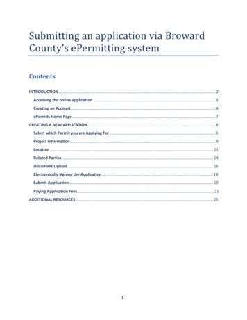
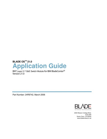
Layer 2-7 GbE Switch Module Application GuideDefault GatewayThe default Gateway IP address determines where packets with a destination address outsidethe current subnet should be sent. Usually, the default Gateway is a router or host acting as anIP gateway to handle connections to other subnets of other TCP/IP networks. If you want toaccess the GbE Switch Module from outside your local network, use the management moduleto assign a default Gateway address to the GbE Switch Module. Choose I/O Module Tasks Configuration from the navigation pane on the left, and enter a default Gateway address (forexample, 192.168.70.125). Click Save.Configure management module for switch accessComplete the following initial configuration steps:1. Connect the Ethernet port of the management module to a 10/100 Mbps network (withaccess to a management station) or directly to a management station.2. Access and log on to the management module, as described in the BladeCenter Management Module User’s Guide on the IBM BladeCenter Documentation CD. The managementmodule provides the appropriate IP addresses for network access (see the applicable BladeCenter Installation and User’s Guide publications on the IBM BladeCenter Documentation CD for more information).3. Select Configuration on the I/O Module Tasks menu on the left side of the BladeCentermanagement module window. See Figure 1-1.24R9742, March 2006Chapter 1: Accessing the Switch 27
Layer 2-7 GbE Switch Module Application GuideFigure 1-1 Switch management on the BladeCenter management module4. You can use the default IP addresses provided by the management module, or you canassign a new IP address to the switch module through the management module. You canassign this IP address through one of the following methods: Manually through the BladeCenter management module. Automatically through the IBM Director Configuration WizardNOTE – If you change the IP address of the GbE Switch Module, make sure that the switchmodule and the management module both reside on the same subnet.Both management module ports (Ethernet 0 and Ethernet 1) must reside on the same subnet.28 Chapter 1: Accessing the Switch24R9742, March 2006
Layer 2-7 GbE Switch Module Application Guide5. Enable the following features in the management module: External Ports (I/O Module Tasks Admin/Power/Restart Advance Setup) External management over all ports (Configuration Advanced Configuration)This setting is required if you want to access the management network through the external ports on the GbE Switch Module.The default value is Disabled for both features. If these features are not already enabled,change the value to Enabled, then Save.NOTE – In Advanced Configuration Advanced Setup, enable “Preserve new IP configuration on all switch resets,” to retain the switch’s IP interface when you restore factory defaults.This setting preserves the management port’s IP address in the management module’s memory,so you maintain connectivity to the management module after a reset.You can now start a Telnet session, Browser-Based Interface (Web) session, or a Secure Shellsession to the GbE Switch Module.Using TelnetUse the management module to access the GbE Switch Module through Telnet. ChooseI/O Module Tasks Configuration from the navigation pane on the left. Select a bay numberand click Advanced Configuration Start Telnet/Web Session Start Telnet Session. ATelnet window opens a connection to the Switch Module (requires Java 1.4 Plug-in).Once that you have configured the GbE Switch Mod
Chapter 10: Server Load Balancing 171 Understanding Server Load Balancing 172 Identifying Your Network Needs 172 How Server Load Balancing Works 173 Implementing Basic Server Load Balancing 175 Network Topology Requirements 176 Configuring Server Load Balancing 177 Additional Server Load Balancing Options 182 Extending SLB Topologies 190