Transcription
C/VM2Verification Method: Framework forFire Safety DesignFor New Zealand Building Code ClausesC1-C6 Protection from Fire
Using this Verification MethodThe Ministry of Business, Innovation and Employment may amend parts of this Verification Methodat any time. People using this Verification Method should check on a regular basis whether newversions have been published. The current version can be downloaded from www.dbh.govt.nz/compliance-documentsUsers should make themselves familiar with the preface to the New Zealand Building CodeHandbook, which describes the status of Verification Methods and explains other ways of achievingcompliance.Defined words (italicised in the text) are explained in the Building Code Clause A2 and in theDefinitions section of this Verification Method. Classified uses of buildings are explained in theBuilding Code Clause A1. Importance levels of building are buildings (italicised in the text) areexplained in the Building Code Clause A3.Enquiries about the content of this document should be directed to:The Ministry of Business, Innovation and EmploymentPO Box 10-729, Wellington.Telephone 0800 242 243Fax 04 494 0290Email: info@dbh.govt.nzISBN: 978-0-478-38164-1 (print)ISBN: 978-0-478-38165-8 (electronic)Acceptable Solutions and Verification Methods are availablefrom www.dbh.govt.nz/compliance-documents Ministry of Business, Innovation and Employment 2014This document is protected by Crown copyright, unless indicated otherwise.The Ministry of Business, Innovation and Employment administers the copyrightin this document. You may use and reproduce this document for your personal useor for the purposes of your business provided you reproduce the documentaccurately and not in an inappropriate or misleading context. You may notdistribute this document to others or reproduce it for sale or profit.The Ministry of Business, Innovation and Employment owns or has licences touse all images and trademarks in this document. You must not use or reproduceimages and trademarks featured in this document for any purpose (except as partof an accurate reproduction of this document) unless you first obtain the writtenpermission of the Ministry of Business, Innovation and Employment.
Status of C/VM2This Verification Method C/VM2, Framework for Fire Safety Design, provides a means of compliance withthe New Zealand Building Code Clauses C1-C6 Protection from Fire. It is issued under section 22 of theBuilding Act 2004 as a Verification Method.This Verification Method is one way that can be used to show compliance with the New Zealand BuildingCode Clauses C1-C6 Protection from Fire. Other ways of complying with the Building Code are described,in general terms, in the preface of the New Zealand Building Code Handbook.When can you use C/VM2This Verification Method is effective from 1 July 2014. It can be used to show compliance with theBuilding Code Clauses C1-C6 Protection from Fire. It does not apply to building consent applicationssubmitted before 1 July 2014.The previous version, Amendment 3, of this Verification Method can be used to show compliancewith the Building Code Clauses C1-C6 Protection from Fire until 28 February 2015. It can be used forbuilding consent applications submitted before 1 March 2015.Document HistoryDateAlterationsNew documentEffective from10 April 2012C/VM2 is a new publication that can be used to show compliancewith the Building Code Clauses C1-C6 Protection from Fire.Amendment 1(Errata 1)Effective from30 April 2012p. 11, 1.2p. 13, Figure 1.1 a)p. 19, Figure 1.1 g)p. 32, Table 2.3p. 39, Table 3.3p. 59, 4.9Amendment 2(Errata 2)Effective from15 February 2013 until18 June 2014p. 9 Definitionspp. 25–26 2.2.1p. 33 Table 2.4p. 40 3.2.4p. 41 3.2.7p. 58 4.8p. 59 4.9p. 61 4.10p. 64 IndexAmendment 3Effective from19 December 2013until 28 February 2015p. 5 Contentsp. 7 Referencesp. 10 Definitionsp. 15 Figure 1.1 cpp. 25–26 2.2.1pp. 28–32 Tables 2.1, 2.2, 2.3p. 35 Table 3.1pp. 39–42 3.2.4, 3.4, Table 3.3pp 49–64 4.4, 4.5, 4.6, 4.7, 4.8,4.9, 4.10, Tables 4.1 and 4.2pp. 66–68 A1.1, A1.4, A1.5,Table A1p. 69 IndexAmendment 4Effective from1 July 2014p. 5–6 Contentspp. 7-8 Referencesp. 10–10A Definitionsp. 11–13 1.2, 1.3, Figure 1.1pp. 14–23 Figure 1.1p. 24 1.5, Table 1.1pp. 25–28, 30–31, 33–33A2.2.1, 2.4, 2.4.4, 2.5,Tables 2.1, 2.2 and 2.4pp. 34–44 3.1, 3.2.4, 3.2.5,3.2.6, 3.3, 3.4, 3.4.1, 3.6.1,3.6.3, 3.6.5, Tables 3.1, 3.2,3.3p. 45 Part 4 Contentspp. 46–47 4.1, 4.2pp. 50–52, 4.5pp. 53–56, 4.6, Table 4.2p. 59 4.7pp. 61–62 4.8p. 63 4.9p. 65 4.10pp. 69–70 A1.6, A1.7, Tables A.1and A.2p. 71 Appendix B, Table B1p. 72 Index
Contents C/VM2ContentsAmend 4Jul 2014Amend 4Jul 2014Amend 4Jul 2014PageReferences7Definitions9Amend 3Dec 20134.8Design scenario: FO Firefightingoperations4.9Design scenario: CF Challenging fire 631Introduction and scope111.1Purpose111.2Scope111.3How to use this Verification Method 111.4Design scenarios: Building Code24objectives and performance criteria1.5Construction24Appendix B (normative): CriticalRadiant Flux values for some flooringmaterials2Rules and parameters for thedesign scenarios25Tables2.1Applying the design scenarios252.2Fire modelling rules252.3Design fire characteristics272.4Full burnout design fires313Movement of people343.1Occupant numbers343.2Required safe egress time (RSET)3.3604.10 Design scenario: RC Robustnesscheck65Appendix A (normative): Establishing 67Group Numbers for lining materialsAmend 3Dec 201371Amend 4Jul 2014Table 1.1: Key features of design scenarios 24Table 2.1: Pre-flashover design firecharacteristics28Table 2.2: Design FLEDs for use inmodelling fires in C/VM230Table 2.3: Fm factors to be appliedto FLED3236Table 2.4: Conversion factor kb forvarious lining materials33ARequirements for delayedevacuation strategies42Table 3.1: Occupant densities353.4Alerting people with warningsystems42Table 3.2: Detector criteria37Table 3.3: Pre-travel activity times393.5Fire modelling to determine ASET433.6Exposure to radiation along egressroutes43Table 3.4: Maximum flow rates for use40in Equation 3.2 for horizontaland vertical travel speeds4Design scenarios45Table 3.5: Boundary layer width usedfor calculating the effectivewidth of an exit component4.1Design scenario: BE Blocked exit464.2Design scenario: UT Fire innormally unoccupied roomthreatening occupants of otherrooms47Table 4.1:564.3Design scenario: CS Fire startsin a concealed space48Table 4.2: Acceptable heat release ratesfor external wall claddingsystems for control ofvertical fire spread4.4Design scenario: SF Smoulderingfire49694.5Design scenario: HS Horizontal firespread50Table A1 Specified performances forsome substrates and coatingcombinationsTable A2 Selection of substrates694.6Design scenario: VS Externalvertical fire spread534.7Design scenario: IS Rapidfire spread involving internalsurface linings57Amend 4Jul 2014Amend 4Jul 2014PageAmend 4Jul 201441Acceptable heat release rates 52Afor external wall claddingsystems for control ofhorizontal fire spreadM IN I S T RY O F BUS IN ES S, INN OVAT I ON A N D EM P LOY M EN T – 1 JULY 2 014Amend 4Jul 2014I5Amend 3Dec 2013Amend 4Jul 2014
Contents C/VM2PageFiguresFigure 1.1: The design process overviewfor C/VM213Amend 4Jul 20146IM IN I S T RY O F BUS IN ES S, INN OVAT I ON A N D EM P LOY M EN T – 1 JULY 2 014Page
References C/VM2ReferencesFor the purposes of New Zealand Building Code (NZBC) compliance, the Standards anddocuments referenced in this Compliance Document (primary reference documents) must bethe editions, along with their specific amendments, listed below. Where these primary referencedocuments refer to other Standards or documents (secondary reference documents), whichin turn may also refer to other Standards or documents, and so on (lower-order referencedocuments), then the version in effect at the date of publication of this Compliance Documentmust be used.Standards New ZealandAmend 3Dec 2013Amend 3Dec 2013NZS 4510: 2008Fire hydrant systems for buildingsAmend: 14.8NZS 4512: 2010Fire detection and alarm systems in buildings3.4NZS 4515: 2009Fire sprinkler systems for life safety in sleepingoccupancies (up to 2000 m2 )DefinitionsNZS 4541: 2013Automatic fire sprinkler systemsDefinitionsAmend 3AS/NZS 3837: 1998 Method of test for heat and smoke release4.6, Tables 4.1, 4.2Dec 2013rates for materials and products using an oxygenconsumption calorimeterAmend: 1Standards AustraliaAS 1366:Part 1: 1992Part 2: 1992Part 3: 1992Part 4: 1989Rigid cellular plastics sheets for thermal insulationRigid cellular polyurethane (RC/PUR)Amend: 1Rigid cellular polyisocyanurate (RC/PIR)Rigid cellular polystyrene – moulded (RC/PS-M)Amend: 1Rigid cellular polystyrene – extruded (RC/PS-E)AS 1530:-Methods for fire tests on building materials,components and structuresCombustibility test for materialsTest for flammability of materialsFire resistance tests for elements of constructionPart 1: 1994Part 2: 1993Part 4: 2005Amend 3Dec 2013AS 4254:Part 1: 2012Part 2: 2012Ductwork for air-handling systems in buildingsFlexible ductRigid duct4.7, A1.74.7, A1.74.7, A1.74.7, A1.7Amend 4Jul 20144.74.72.44.7, A1.4British Standards InstitutionBS 7273:Part 4: 2007Code of practice for the operation of fireprotection measuresActuation of release mechanisms for doors4.10International Standards OrganisationISO 1182: 2010Reaction to fire tests for products –Non-combustibility test4.7ISO 5660:Reaction-to-fire testsPart 1: 2002Heat release, smoke production and massloss rate4.6, 4.7, A1.1, A1.2,A1.3, A1.7Tables 4.1, 4.2Part 2: 2002A1.1Smoke production rate (dynamic measurement)M IN I S T RY O F BUS IN ES S, INN OVAT I ON A N D EM P LOY M EN T – 1 JULY 2 014IAmends3 and 47
References C/VM2ISO 9239:Part 1: 2010Reaction to fire tests for flooringsDetermination of the burning behaviour usinga radiant heat sourceISO 9705: 1993Fire tests – Full-scale room test for surfaceproducts4.7, A1.1, A1.2, A1.7ISO 13571: 2007Life-threatening components of fireGuidelines for the estimation of time availablefor escape using fire data.2.2.1ISO 13784:-Reaction-to-fire tests for sandwich panel buildingsystemsTest method for small roomsA1.1, A1.7Reaction-to-fire tests for façadesIntermediate-scale test4.6Part 1: 2002ISO 13785:Part 1: 20024.7, B1.0Table B1,Amend 4Jul 2014Amend 4Jul 2014European Committee for StandardisationEurocode DD ENV 1991:- Eurocode 1: basis of design andactions on structures,Part 2.2: 1996 Actions on structures exposed to fire2.4 Comment,2.4.4National Fire Protection Association of AmericaNFPA 285: 1998Standard method of test for the evaluation of4.6flammability characteristics of exterior non-loadbearing wall assemblies containing componentsusing the intermediate scale, multi-storeytest apparatusBRANZ LtdBRANZ Study Report No. 137: 2005 Development of the VerticalChannel Test Method for Regulatory Control ofCombustible Exterior Cladding Systems,Whiting, P. N.4.6Australian Building Codes BoardInternational Fire Engineering Guidelines (IFEG): 20051.3 CommentAmend 4Jul 2014Society of Fire Protection EngineersThe Handbook of Fire Protection Engineering, 4th Edition,National Fire Protection Association,Quincy, M.A, USA, 2008.Gwynne, S.M.V, and Rosenbaum, E.R, “Employingthe Hydraulic Model in Assessing EmergencyMovement”, Section 3 Chapter 13.3.2 Comment3.2.6 CommentSFPE Engineering Guide to Predicting 1st and 2nd Degree Skin Burns3.6.1from Thermal Radiation, 2000General publicationsFire Engineering Design Guide (Centre for AdvancedEngineering, 2008)8IM IN I S T RY O F BUS IN ES S, INN OVAT I ON A N D EM P LOY M EN T – 1 JULY 2 0142.4.4 Comment
Definitions C/VM2DefinitionsThe full list of definitions for italicised words may be found in the New Zealand BuildingCode Handbook.Available safe egress time (ASET)Time available for escape for an individualoccupant. This is the calculated time intervalbetween the time of ignition of a fire and thetime at which conditions become such thatthe occupant is estimated to be incapacitated(ie, unable to take effective action to escapeto a place of safety).Burnout Means exposure to fire for a timethat includes fire growth, full development,and decay in the absence of intervention orautomatic suppression, beyond which thefire is no longer a threat to building elementsintended to perform loadbearing or fireseparation functions, or both.Computational fluid dynamics (CFD)Calculation method that solves equationsto represent the movement of fluids in anenvironment.Design fire Quantitative description of assumedfire characteristics within the design scenario.Design scenario Specific scenario on whicha deterministic fire safety engineering analysisis conducted.Detection time Time interval betweenignition of a fire and its detection by anautomatic or manual system.Evacuation time Time interval betweenthe time of warning of a fire being transmittedto the occupants and the time at which theoccupants of a specified part of a buildingor all of the building are able to enter a placeof safety.Fire decay Stage of fire development aftera fire has reached its maximum intensityand during which the heat release rate andthe temperature of the fire are decreasing.Fire growth Stage of fire developmentduring which the heat release rate andthe temperature of the fire are increasing.Fire load Quantity of heat which can bereleased by the complete combustion of all thecombustible materials in a volume, includingthe facings of all bounding surfaces (Joules).Fire safety engineering Application ofengineering methods based on scientificprinciples to the development or assessmentof designs in the built environment throughthe analysis of specific design scenarios orthrough the quantification of risk for a groupof design scenarios.Flashover Stage of fire transition to a stateof total surface involvement in a fire ofcombustible materials within an enclosure.Fractional effective dose (FED) The fractionof the dose (of carbon monoxide (CO) orthermal effects) that would render a personof average susceptibility incapable of escape.Comment:The definition for FED has been modified from theISO definition to be made specific for this VerificationMethod. The ISO definition is ”Ratio of the exposuredose for an insult to that exposure dose of the insultexpected to produce a specified effect on an exposedsubject of average susceptibility.”Fully developed fire State of totalinvolvement of combustible materials in a fire.Heat of combustion Thermal energyproduced by combustion of unit massof a given substance (kJ/g).Heat release Thermal energy producedby combustion (Joules).Heat release rate (HRR) Rate of thermalenergy production generated by combustion(kW or MW).Importance level As specified in Clause A3of the Building Code.Errata 2Feb 2013Incapacitated State of physical inabilityto accomplish a specific task.Insulation In the context of fire protection,the time in minutes for which a prototypespecimen of a fire separation, whensubjected to the standard test for fireresistance, has limited the transmission ofheat through the specimen.Fire load energy density (FLED) Fire loadper unit area (MJ/M2 ).M IN I S T RY O F BUS IN ES S, INN OVAT I ON A N D EM P LOY M EN T – 15 F EB RUA RY 2 013I9
Definitions C/VM2Integrity In the context of fire protection,the time in minutes for which a prototypespecimen of a fire separation, whensubjected to the standard test for fireresistance, has prevented the passage offlame or hot gases.Comment:The precise meaning of integrity depends on thetype of building elements being treated and how it isdefined in the standard test being used.Response Time Index (RTI) The measureof the reaction time to a fire phenomenon ofthe sensing element of a fire safety system.Safe place A place, outside of and in thevicinity of a single building unit, from whichpeople may safely disperse after escaping theeffects of a fire. It may be a place such as astreet, open space, public space or anadjacent building unit.Comment:Optical density of smoke Measure of theattenuation of a light beam passing throughsmoke expressed as the logarithm to thebase 10 of the opacity of smoke.The Fire Safety and Evacuation of BuildingsRegulations 2006 use the term ‘place of safety’ andallow the place of safety to be within the buildingprovided that it is protected with a sprinkler system.Opacity of smoke Ratio of incident lightintensity to transmitted light intensity throughsmoke under specified conditions.Separating element Barrier that exhibitsfire integrity, structural adequacy, thermalinsulation, or a combination of these for aperiod of time under specified conditions(in a fire resistance test).Place of safety means either—a) a safe place; orb) a place that is inside a building and meetsthe following requirements:i) the place is constructed with fireseparations that have fire resistancesufficient to withstand burnout at thepoint of the fire source; andAmends 3and 4Smoke production rate Amount of smokeproduced per unit time in a fire or fire test.Smoke separation Any building elementable to prevent the passage of smoke betweentwo spaces. Smoke separations shall:a) Be a smoke barrier complying withBS EN 12101 Part 1, orii) the place is in a building that isprotected by an automatic fire sprinklersystem that complies with NZS 4541or NZS 4515 as appropriate to thebuilding’s use; andb) Consist of rigid building elements capableof resisting without collapse:iii) the place is designed to accommodatethe intended number of persons at adesign occupant density – dependingon the usage this shall not be less than1.0 m2 per person; andii) self weight plus the intended verticallyapplied live loads, andiv) the place is provided with sufficientmeans of escape to enable the intendednumber of persons to escape to a safeplace that is outside a building.i) a pressure of 0.1 kPa applied fromeither side, andc) Form an imperforate barrier to the spreadof smoke, andd) Be of non-combustible construction, orachieve a FRR of 10/10/-, except thatnon-fire resisting glazing may be used if itis toughened or laminated safety glass.Pre-travel activity time Time period afteran alarm or fire cue is transmitted and beforeoccupants first travel towards an exit.Required safe egress time (RSET) Timerequired for escape. This is the calculatedtime period required for an individualoccupant to travel from their location at thetime of ignition to a place of safety.10IM IN I S T RY O F BUS IN ES S, INN OVAT I ON A N D EM P LOY M EN T – 1 JULY 2 014Amend 4Jul 2014
Verification Method C/VM2Comment:The pressure requirement is to ensure rigidity and isnot a smoke leakage requirement.Walls and floors, whether constructed of sheet liningsfixed to studs or joists, or of concrete, glazing, metalor fired clay, need only be inspected by someoneexperienced in building construction to judge whetherthe construction is tight enough to inhibit the passageof smoke.Item d) is intended to ensure that the smokeseparation will continue to perform as an effectivebarrier when exposed to fire or smoke for a shortperiod during fire development.Amend 4Jul 2014There is no requirement for smoke control doors orother closures in smoke separations to meet theprovisions of item d).Specific extinction area of smokeExtinction area of smoke produced by a testspecimen in a given time period, divided bythe mass lost from the test specimen in thesame time period.Structural adequacy In the context of thestandard test for fire resistance, is the timein minutes for which a prototype specimenhas continued to carry its applied load withindefined deflection limits.Surface spread of flame Flame spread awayfrom the source of ignition across the surfaceof a liquid or a solid.Travel distance Distance that is necessaryfor a person to travel from any point within abuilt environment to the nearest exit, takinginto account the layout of walls, partitionsand fittings.Visibility Maximum distance at whichan object of defined size, brightness andcontrast can be seen and recognised.Yield Mass of a combustion productgenerated during combustion dividedby the mass loss of the test specimen.M IN I S T RY O F BUS IN ES S, INN OVAT I ON A N D EM P LOY M EN T – 1 JULY 2 014I10A
Verification Method C/VM2This page deliberately left blank10 BID EPA R T M EN T O F BUI L D ING A N D H OUS ING – 10 A P R I L 2 012
Verification Method C/VM21 Introduction and scope1.1PurposeCONTENTS1.1Purpose1.2Scope1.3How to use this Verification Method1.4Design scenarios: Building Codeobjectives and performance criteriaThis is a Verification Method for the specificdesign of buildings to demonstrate compliancewith NZBC C1 to C6 Protection from Fire.It is suitable for use by professional fireengineers who are proficient in the useof fire engineering modelling methods.1.2ScopeThis Verification Method can be applied to firedesigns for all buildings.Comment:This Verification Method will usually be used for firedesigns that, for whatever reason, cannot be shownto comply with NZBC C: Protection from Fire usingthe relevant Acceptable Solutions C/AS1 to C/AS7.However, a designer may opt to use this VerificationMethod even if the building could be designed usingthe Acceptable Solutions.Errata 1Apr 2012There are some minor exceptions to ‘all buildings’,for example tunnels and open air stadia. Users shouldrefer to the Commentary to this Verification Methodfor further information.1.3Amend 4Jul 2014How to use this Verification MethodThis Verification Method sets out 10 designscenarios that must each be considered anddesigned for, where appropriate, in order toachieve compliance with NZBC C: Protectionfrom Fire.The concept fire design shall be trialled usingbuilding specific fire design requirementsascertained via the Fire Engineering Brief(FEB) process as described in internationallyrecognised fire engineering processdocuments.Comment:There are a number of internationally recognisedprocess documents including the International FireEngineering Guidelines and others published by BritishStandards and the Society for Fire Protection Engineers.Follow the process schematically illustrated inFigure 1.1 as appropriate, analysing or testingthe fire design against the design scenariosas applicable and modelling the designscenario: CF Challenging Fire (see Paragraph4.9) a number of times with the design firepositioned in the most challenging locations.M IN I S T RY O F BUS IN ES S, INN OVAT I ON A N D EM P LOY M EN T – 1 JULY 2 014I11Amend 4Jul 2014
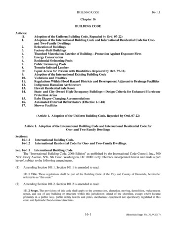
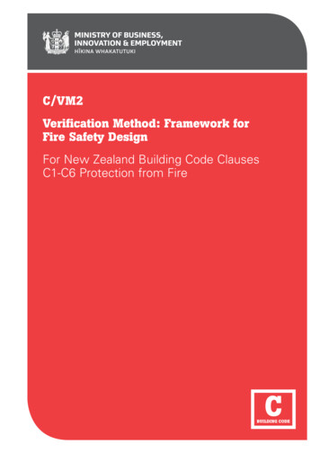
Verification Method C/VM2Comment:ASET/RSET and other computational modelling is onlyrequired for a few of the design scenarios. Many can besatisfied by inspection or by providing certain features(eg, fire separations or smoke detection systems).In many cases the location that is the most challenging(that which will provide the shortest ASET/RSET ) willbe easily determined.In Figure 1.1, the numbered references are toparagraph numbers in this VerificationMethod.Figure 1.1 is guidance information illustratinghow the use of this Verification Method – inparticular the design scenarios – fits into thegeneral iterative fire design process. Theflowchart assumes design starts at conceptdesign stage. The sequence of assessingeach of the design scenarios may vary fromthat idealised in Figure 1.1. The designprocess outlined in the flowchart will varywhen using this Verification Method forassessing Code compliance of existingbuildings. The overall process described inFigure 1.1 is not itself a normative part ofC/VM2.Amends 3and 4The communication process relating to FEBdevelopment will vary for each project andmay include both written and verbalcommunication to collect stakeholderconsiderations and test options whenpreparing trial designs. Similarly, the form ofFEB documentation will vary depending onthe complexity and scale of the project andthe design issues. The key features of boththe FEB communication and documentationare that it is unambiguous, complete (i.e.provided with appropriate context) andrecorded in some form for later reference.12IM IN I S T RY O F BUS IN ES S, INN OVAT I ON A N D EM P LOY M EN T – 1 JULY 2 014
Verification Method C/VM2Figure 1.1: The design process overview for C/VM2Concept Occupant characteristics Initial determination of activeand passive fire safety systemsthat are preferred Design will not use anAcceptable Solution Inputs determined from datain Verification Method Scenario CF(challenging fire) locations Design fire(s) to use in modelling Fire load energy density Occupant related data Active system inputs(alarms and sprinklers)FEB ReportDrafting of FEBDocumentationCommunicateconcept ider changeto conceptdesignRevise draft FEBdocumentationStakeholderfeedback leads torevision?NoNoYesPrepare trialdesignRevise trialdesignVM2 EvaluationBE4.1UT4.2CS4.3SF4.4HS4.5Complies withall scenarios?Will trialdesign cument theprocess and thedesignApprovalAmend 4Jul 2014M IN I S T RY O F BUS IN ES S, INN OVAT I ON A N D EM P LOY M EN T – 1 JULY 2 014I13
Verification Method C/VM2Pages 14 – 23 deleted by amendment 414ID EPA R T M EN T O F BUI L D ING A N D H OUS ING – 10 A P R I L 2 012
Verification Method C/VM2This page deliberately left blankM IN I S T RY O F BUS IN ES S, INN OVAT I ON A N D EM P LOY M EN T – 1 JULY 2 014I23
Verification Method C/VM21.41.5 ConstructionDesign scenarios: Building Codeobjectives and performance criteriaDetailing during construction shall meet therequirements of the design as developedusing this Verification Method.The design scenarios specified in Part 4 aresummarised in Table 1.1 (with paragraphnumbers given in brackets for ease ofreference). Each scenario must be consideredseparately to achieve the Building Codeobjectives and to satisfy the performancecriteria of the Building Code clauses shown.Comment:For example:1. Fire rated closures including doors have to betested in accordance with an internationallyrecognised standard to confirm the FRR.2. Fire and smoke separations should be firestopped with appropriate proprietary productsfor the orientation and be specific for use in thatseparating element.Table 1.1Key features of design scenariosDesign scenarioBuilding CodeobjectivesBuilding CodecriteriaExpected methodC1(a)C4.5Solved by inspectionC1(a)C4.3, C4.4ASET/RSET analysis or provide separatingelements /suppression complying with arecognised StandardC1(a)C4.3Provide separating elements /suppression orautomatic detection complying with a recognisedStandardC1(a)C4.3Provide automatic detection and alarm systemcomplying with a recognised StandardC1(b)C3.4Suitable materials used (proven by testing)C1(a)C4.3, C4.4ASET/RSET analysisC1(a), C1(b),C1(c)C3.9, C4.5,C5.8, C6.2(d)Modified ASET/RSET analysisC1(b), C1(a)C3.6, C3.7,C4.2Calculate radiation from unprotected areasas specifiedExternal vertical fire spreadC1(a),C3.5(4.6)C1(b)Suitable materials used (proven by testing)and construction features specified (eg, aprons/spandrels/sprinklers) as required to limit verticalfire spreadC3.8, C5.3,C5.4, C5.5,C5.6, C5.7,C5.8, C6.3Demonstrate firefighter safetyKeeping people safeBEFire blocks exit(4.1)UTFire in a normally unoccupiedroom threatening occupantsof other rooms(4.2)CSFire starts in a concealed space(4.3)SFSmouldering fire(4.4)ISRapid fire spread involvinginternal surface linings(4.7)CFChallenging fire(4.9)RCRobustness check(4.10)Protecting other propertyHSHorizontal fire spread(4.5)Amend 4Jul 2014VSFirefighting operationsFO24IFirefighting operationsC1(b),(4.8)C1(c)M IN I S T RY O F BUS IN ES S, INN OVAT I ON A N D EM P LOY M EN T – 1 JULY 2 014Amend 4Jul 2014
Verification Method C/VM2Part 2: Rules and parameters for thedesign scenarios2.2Fire modelling rulesCONTENTS2.1Applying the design scenarios2.2Fire modelling rules2.3Design fire characteristics2.4Full burnout design fires2.1Applying the design scenariosThis Verification Method sets out 10 designscenarios that must each be considered anddesigned for, where appropriate, in order toachieve compliance with NZBC C1-C6:Protection from Fire.This section sets out the fire modelling rules,design fire characteristics and other parametersto be used in calculations required by thedesign scenarios. Occupancy criteria andcalculations for the movement of people areprovided in Part 3.The fire modelling rules in Paragraphs 2.2.1and 2.2.2 shall be applied to the designscenarios as appropriate.2.2.1 Fire modelling rules for life safetydesignThe model to be used, and the spaces orvolumes to be modelled, shall be establishedat FEB.The trial design shall identify the type ofseparations (eg fire separation, smokeseparation or unrated construction) andclosures (eg fire or smoke control doors etc)proposed, and which of these are relevant forinclusion in the analysis. These modellingrules detail the assumptions to be maderegarding the different types of separation orclosure. These modelling rules are notintended to imply that it is necessary toinclude all separations and closures in theanalysis. Only those separations and closuresforming the volumes required to demonstratethe safe evacuation of occupants need beconsidered in an ASET analysis.Amend 4Jul 2014Fire modelling rules for life safety design shallbe as follows:a) Warning systems in accordance withParagraph 3.4 shall be installed.b) Fire and smoke control doors with selfclosers complying with a recognisednational or international Standard areassumed closed unless being used byoccupants. During egress, when occupantload is low, doors are assumed to be openfor three seconds per occupant. However,when the occupant load is high andqueuing is expected, the door is consideredto be open for the duration of queuing.c) Smoke control doors serving bedrooms insleeping areas where care is provided(these do not have self closers) shall beconsidered to be closed from the time thatevacuation from the bedroom is completedin accordance with Paragraph 3.2 andTable 3.3.
with the Building Code Clauses C1-C6 Protection from Fire until 28 February 2015. It can be used for building consent applications submitted before 1 March 2015. Status of C/VM2 This Verification Method C/VM2, Framework for Fire Safety Design, provides a means of compliance with the New Zealand Building Code Clauses C1-C6 Protection from Fire.