Transcription
GX270 HONDA9270-03-01EX270 SUBARU9270-06-01CH395 KOHLER9390-02-01GX390 HONDA9400-03-01EX400 SUBARU9570-04-01MAN 4166749Rev. B 02-2017Original Language Instructions570 VANGUARDOwners Manual and Safety Instructions forOPTIMAX BLOWEROPERATORS / PARTS MANUALMODELS: 9270-02-01
CALIFORNIAWARNINGProposition 65 WarningDiesel engine exhaust and someof its constituents are known to theState of California to cause cancer,birth defects and other reproductiveharm.The engine exhaust from this productcontains chemicals known to the Stateof California to cause cancer, birthdefects or other reproductive harm.CALIFORNIAProposition 65 WarningBattery posts, terminals, wiringinsulation, and related accessoriescontain lead and lead compounds,chemicals known to the State ofCalifornia to cause cancer and birthdefects or other reproductive harm.WASH HANDS AFTER HANDLING.
LITTLEWONDERBLOWERIMPORTANT MESSAGEOn behalf of everyone at Little Wonder, we would like to thank you for your purchase of a Little Wonder GasolinePowered Optimax Blower. This professional blower was designed to the highest standards to ensure you manyhours of uninterrupted service.This manual provides the information necessary for safe and efficient operation and service. For your safety, itis critically important that you read and understand this entire manual before operating your blower.LITTLE WONDERSCHILLER GROUNDS CARE, INC.1028 STREET ROAD, P.O. BOX 38SOUTHAMPTON, PA 18966TABLE OF CONTENTSFIGURESPAGESAFETY.4-8SET UP INSTRUCTIONS.9-10CONTROLS. 11OPERATION / MAINTENANCE. 12ADJUSTMENTS. 13STORAGE / TORQUE SPECIFICATIONS. 14INTAKE GUARD ASSY. FIGURE 1. 15ENGINE ASSY. FIGURE 2. 16HOUSING ASSY. FIGURE 3. 17WARRANTY. BACK COVERMANY USES:The extreme versatility offered by Little Wonder’s line of blowers makes them ideally suited for a wide varietyof jobs; blowing leaves, grass clippings, thatch, blowing tennis courts dry, cleaning large driveways, stadiums,parking lots and other hard surfaces, precleaning roofs before repair and countless other jobs.This Operator’s Manual is part of the machine. Suppliers of both new and secondhand machines must make sure that this manual is provided with the machine.02-20173
LITTLEWONDERBLOWERSAFETYThis symbol means:NOTICE !!!Unauthorized modifications may present extremesafety hazards to operators and bystanders andcould also result in product damage.Schiller Grounds Care, Inc. strongly warns against,rejects and disclaims any modifications, add-onaccessories or product alterations that are notdesigned, developed, tested and approved by SchillerGrounds Care, Inc. Engineering Department. AnySchiller Grounds Care, Inc. product that is altered,modified or changed in any manner not specificallyauthorized after original manufacture-including theaddition of “after-market” accessories or componentparts not specifically approved by Schiller GroundsCare, Inc.-will result in the Schiller Grounds Care,Inc. Warranty being voided.Any and all liability for personal injury and/orproperty damage caused by any unauthorizedmodifications, add-on accessories or products notapproved by Schiller Grounds Care, Inc. will beconsidered the responsibility of the individual(s) orcompany designing and/or making such changes.Schiller Grounds Care, Inc. will vigorously pursuefull indemnification and costs from any partyresponsible for such unauthorized post-manufacturemodifications and/or accessories should personalinjury and/or property damage result.ATTENTION!BECOME ALERT!Your safety and the safety of others is involved.Signal word definitions:The signal words below are used to identify levelsof hazard seriousness. These words appear in thismanual and on the safety labels attached to SchillerGrounds Care, Inc. machines. For your safety andthe safety of others, read and follow the informationgiven with these signal words and/or the symbolshown above.DANGER indicates an imminently hazardoussituation which, if not avoided, WILL result in deathor serious injury.WARNING indicates a potentially hazardoussituation which, if not avoided, COULD result indeath or serious injury.CAUTION indicates a potentially hazardous situationwhich, if not avoided, MAY result in minor or moderateinjury. It may also be used to alert against unsafepractices or property damage.Schiller Grounds Care, Inc.1028 Street RoadSouthampton, PA 18966 U.S.APhone: 215-357-5110Fax: 215-357-8045MODEL NUMBER4SERIAL NUMBERCAUTION used without the safety alert symbolindicates a potentially hazardous situation which, ifnot avoided, MAY result in property damage.MODEL NUMBER: This number appears onsales literature, technical manuals and price lists.SERIAL NUMBER: This number appears onlyon your unit. It contains the model number followed consecutively by the serial number. Usethis number when ordering parts or seeking warranty information.
LITTLEWONDERBLOWERSAFETYMACHINE PREPARATIONOperator preparation and trainingRead the Operation & SafetyManual– If an operator or mechaniccannot read English, it isthe owner's responsibilityto explain this material tothem. If any portion ofthis material is unclear,contact your factoryrepresentative for clarification.–SITE PREPARATION AND CIRCUMSTANCES–Evaluate the terrain to determine how to safelyperform the job. Only use accessories andattachments approved by the manufacturer.–Be sure the area is clear of pets and people,especially young children. Never assume theywill remain where you last saw them. Stop themachine if any enter the area.Become familiar with the safe operation of theequipment, operator controls and safety signs.Be prepared to stop the engine quickly in anemergency. Do not operate or allow anotherperson to operate this machine if there are anyquestions about safety.MULTIPLE OPERATORS–All operators and mechanics should be trained.The owner is responsible for training the users.––Wear appropriate clothing, including safetygoggles or safety glasses with side shields whenoperating. Wear substantial footwear. Do notoperate barefoot or wearing open sandals. Longhair, loose clothing or jewelry may get tangled inmoving parts.Do not tamper with or defeat safety devices.Keep guards, shields and interlock safety devicesin place and in proper working condition. Theyare for your protection.–Keep all fasteners such as nuts, bolts and pinswell secured.–Verify that machine and attachments, if any, arein good operating condition.–Wear appropriate hearing protection.Wear dust mask to avoid breathing dust.–Wear safety glasses.–Never allow children, unskilled or improperlytrained people to operate this equipment. Localregulations can restrict the age of the operator.–Keep warning labels and this operator's manuallegible and intact. Replacement labels andmanuals are available from the factory.–Do not operate machine while under theinfluence of drugs or alcohol, or any othercondition of impairment.–The owner/user can prevent and is responsiblefor accidents or injuries occurring to themselves,other people or property.–Keep a safe distance between operators whenworking together.MACHINE PREPARATION5
LITTLEWONDERBLOWERSAFETYOPERATING SAFELYIN GENERAL–Use extra care when loading or unloading themachine into a trailer or truck.–Do not run the engine in an enclosed area wheredangerous carbon monoxide fumes can collect.–Never leave a running machine unattended.Always stop engine when leaving the operatorposition.–Do not blow towards people, cars, windows, orother items which could be injured or damagedby the blown debris.–Keep hands away from the blower air intake andoutlet.INTERRUPTING OPERATION- Before leaving the operator's position:- Park on level ground.- Shut off the engine.-Stop the engine, and wait until the fan stopsmoving:- before refueling;-Stop the engine, and disconnect the spark plugwire(s):- before clearing blockages;- before checking, cleaning or working on themachine;- if the machine begins to vibrate abnormally:shut off machine immediately. Inspectand have repairs made as needed beforerestarting;STARTING–Start according to instructions in this manual oron the machine.–Do not change engine governor settings oroverspeed the engine. Operating the engineat excessive speed can increase the hazard ofpersonal injury.- except for repairs or adjustments as specificallynoted, such as for carburetor adjustment,where the engine must be running. Keephands and feet clear of moving parts in thesecircumstances.-Allow the fan to come to a complete stop whenstopping operation to clear blockages, unclog,inspect the machine, do maintenance or repair.-Reduce the throttle setting during engine shutdown and, if the engine is provided with a shutoff valve, turn the fuel off at the conclusion ofoperation.OPERATING ON SLOPESUSE EXTRA CARE WHEN OPERATING ON SLOPES.EVALUATE THE RISKS INVOLVED BEFORE OPERATING ON A SLOPE.- Slopes are a major factor related to slip and fallaccidents that sometimes lead to severe injury ordeath. All slopes require extra caution.-Do not operate on slopes if uneasy or uncertain.Ultimate responsibility for safe operation on slopesrests with the operator.-Do not operate on steep slopes. Poor footing couldcause a slip and fall accident.-Keep all movement on slopes slow and gradual.-Do not operate near drop-offs, ditches or embankments. You could lose your footing or balance.-Do not turn on slopes unless necessary, and thenturn slowly and downhill when possible.-Be sure of your footing on slopes.-Watch for holes, ruts, bumps, rocks and other hidden objects. Uneven terrain could cause a slip andfall accident. Tall grass can hide objects.6
LITTLEWONDERBLOWERSAFETYMAINTENANCE SAFETYIn general--Maintain machine according to manufacturer'sschedule and instructions for maximum safetyand best results.-Park machine on level ground.-Never allow untrained personnel to service machine.-Guards should only be removed by a qualifiedtechnician for maintenance or service.-Adjust or repair only after the engine has beenstopped and the fan has stopped moving.-Disconnect spark plug wire(s) before doing anymaintenance.-Replace parts if worn, damaged or faulty.For best results, always replace with partsrecommended by the manufacturer.-Do not dismantle the machine without releasingor restraining forces which may cause parts tomove suddenly.-Provide adequate support, e.g. jack stands forlifted machine or parts if working beneath.-Do not put hands or feet near or under rotatingparts.-Clean up spilled oil or fuel thoroughly.-Replace faulty mufflers.-To reduce fire hazards, keep the engine, muffler, and fuel storage area free of grass, leaves,debris buildup or grease.FansDo not straighten or weld fans. Replace damaged or failed fans.Fuel--Gasoline (petrol)) and diesel fuels are flammable;gasoline (petrol) vaporsare explosive. Use extracare when handling.Store only in containersspecifically designed forfuel.WARNINGWhen refueling or checking fuel level:- Stop the engine and allow to cool;- Do not smoke;- Refuel outdoors only;- Use a funnel;- Do not overfill;- If fuel is spilled, do not attempt to start theengine until the spill is cleaned up and vaporshave cleared.- Replace caps on fuel containers and tankssecurely.Sparks from static electricity can start fires orcause explosions. Flowing fuel can generate staticelectricity. To prevent static electricity sparks:-Keep containers electrically grounded. Do not fillcontainers in a vehicle or on a truck or trailer bedwith a plastic liner. Fill containers on the groundaway from the vehicle.-When practical, remove petrol (gasoline)powered equipment from the truck or trailerand refuel it on the ground. If equipment mustbe refueled on the truck or trailer, refuel froma portable container rather than a dispensernozzle.-Keep the dispenser nozzle in contact with the rimof the fuel tank or container opening until fuelingis complete. Do not use a nozzle lock-opendevice.-If fuel is spilled on clothing change it immediately.STORAGE SAFETY-Stop the engine and allow to cool before storing.-Drain the fuel tank outdoors only.-Store fuel in an approved container in a cool, dryplace.-Keep the machine and fuel containers in a lockedstorage place to prevent tampering and to keepchildren from playing with them.-Do not store the machine or fuel container near anopen flame, spark, or appliance, such as a waterheater, or a pilot light.-Keep petrol (gasoline) storage area free of grass,leaves and excessive grease to reduce fire hazard.-Clean grass and debris from cutting units, drives,mufflers and engine to help prevent fires.7
LITTLEWONDERBLOWERSAFETYSAFETY DECALSAn important part of the safety system incorporated in this blower are the warning labels found on the blower.Replace labels if damaged or illegible.WARNINGADVERTENCIAAntes de comenzar:BEFORE STARTING:-Read and understand Operatormanual and labels.-Wear hearing and eye protection.-Replace labels and Operatormanual if lost or damaged.-Lea y entienda el manual deloperador y las etiquetas.-Pide que alguien lea y explique elmanual y las etiquetas a usted siusted no lee Inglés.-Use protección ocular y auditiva.-No haga funcionar sin losprotectores en su lugar.-Pare el motor antes de dar servicio-La gente a más durante laoperación.4165977DANGERFan blades can cut/crush.-Keep hands and feet away.-Stop engine and remove spark plugwire before servicing.-Do not operate without guards inplace.WARNINGDEFLECTORThrown objects-Keep bystanders away.-Do not blow toward people or pets.-Do not blow toward items that maybe damaged by flying debris.4165975841659134165913 USED ON REMOTEHORIZONTAL DEFLECTOR MODELSONLY
SET-UP INSTRUCTIONSLITTLEWONDERBLOWERSET-UP INSTRUCTIONS1. Open box. Remove upper handle and cardboardinsert.2. Lay box down with blower housing up. Use lowerhandle to roll unit out of the box.3. Locate hardware package.4. Install upper handle to lower handle with (4) 3/8-16x 1-34 carriage bolts and (4) 3/8-16 flanged nyloninsert nuts from the hardware package. Tighten thenuts securely but not so much as to crush the tube.(Figure 1)FIGURE 15. Route the throttle cable in front of lower handlecrossbar. Install to the left side of the upper handlewith (2) 10-32 x ½ thread forming screws from thehardware package. (Figure 2)6. Ensure the center link of the chain is on the centertooth of the deflector sprocket before connecting thedeflector cable. (Figure 5)FIGURE 2FIGURE 59
SET-UP INSTRUCTIONSLITTLEWONDERBLOWERSET-UP INSTRUCTIONS (continued)7. Route the deflector cable above the axle and infront of the lower handle cross bar. Remove one ofthe nuts and the boot from the end of the deflectorcable and install the cable through the key slot intothe bracket on the upper handle. Reconnect theclevis from the control lever and install over the endof the cable. Reconnect the clevis to the controllever with a ¼ x 5/8 clevis pin and hairpin cotter.(Note: The deflector can be moved and held inplace with the locking knob to help connect theclevis fitting to the control lever. Move the controllever to the rear to more easily connect the cable.Loosen the knob so the deflector moves freely afterthe clevis is connected. (Figure 3)8. Move the deflector control lever to the rear of theslot. Adjust the jam nuts on the cable fitting sothe deflector is completely closed. Lock the nutsagainst the bracket when the adjustment is correct.9. Secure the throttle and deflector cables to thehandle tubes with cable ties from the hardwarepackage. Trim off excess. (Figure 4)10.10Fill the engine with oil to the level indicatedon the dipstick. Fill the fuel tank with clean, freshregular grade unleaded gasoline.FIGURE 4FIGURE 3
LITTLEWONDERBLOWERCONTROLS(BLOWER SHOWN WITH SUBARU EX40 ENGINE.OTHER ENGINES ARE SIMILAR.)SWITCH (A)Move to the “OFF” position to stop the engine.Move to the “ON” position before starting engine.THROTTLE (B)Controls engine speed and the amount of airbeing blown.CHOKE (C)Move to the “CHOKE” position to apply thechoke. Move to the “RUN” position to removethe choke.FUEL SHUT OFF (D)Move to the “OFF” position to shut off the fuelwhenever transporting the machine by traileror truck or during storage. Move to the “ON”position before starting the engine.REMOTE HORIZONTAL DEFLECTOR LEVER (E)Move the lever forward to direct the flow of airdown. Move the lever back to direct the flow ofair up.LOCKING KNOB (F)Tighten the knob to lock the horizontal deflectorin the desired position. Loosen to allow thedeflector to be rotated with remote horizontaldeflector lever.VERTICAL DEFLECTOR (G)Rotate the deflector to direct air dischargeforward or to the side.HORIZONTAL DEFLECTOR (H)Directs air flow. Controlled by Remote HorizontalDeflector Lever E. May be locked in place withknob F.11
LITTLEWONDERBLOWEROPERATION / MAINTENANCEBEFORE STARTING THE ENGINE1. Read the Operator Manual and Engine Manual.Become familiar with the controls, how each functions, and what it operates.2. Check the engine oil level and add if necessary.3 Fill the fuel tank with good quality, clean, unleadedregular gasoline (petrol). Use a funnel to avoidspilling.OPERATING INSTRUCTIONSAir flow can be directed to the side or front by thetwo-position vertical deflector. The front dischargeposition is used to remove debris from along walls,fences, etc. The side discharge position is used toform windrows or piles. The horizontal deflectordirects air downward to “chisel” under wet, heavyleaves and litter. Air velocity is regulated by thethrottle setting.To reduce windrowing or to blow over an obstacle,point deflector upward.To avoid blowing in an area, close deflector andreduce throttle setting.Slight changes in deflector position will have a bigeffect on air flow. Experiment until you find the bestposition for your needs.When clearing a yard or parking lot, a little time spentplanning how to blow it off can greatly reduce thetotal clearing time.To stop the engine, move the throttle control to theslow position and switch the engine off.Stop the engine when moving from work site to worksite. This will save fuel and prevent inadvertentlyblowing debris where you don’t want to.NOTE: When transporting the machine by truck ortrailer, close the fuel valve. This avoids the possibility of flooding should any dirt get under the carburetor float needle. Leaving the valve open can allowsevere flooding which may ruin the engine by dilutingthe oil.12MAINTENANCE INSTRUCTIONSStop engine and remove the spark plug wire beforeperforming any maintenance.Keep blower air intake clear of debris for bestperformance.Clear air discharge area of any debris accumulation.Ensure machine has been shut off and fan is nolonger moving before clearing.Keep all hardware tight.Check oil level daily. Top off as needed.Change engine oil after the first 5 hours of operation.Then change as recommended by the enginemanufacturer.1. Remove drain plug and drain oil while engine iswarm.2. Replace drain plug, remove fill plug andfill with new oil. See engine manual for oilspecifications.3. Start and run engine for 30 seconds. Stopengine.4. Wait 30 seconds, then re-check oil level.5. Top off if necessary. See engine manual fordetails.
ADJUSTMENTSLITTLEWONDERBLOWERDEFLECTOR LEVERDEFLECTOR CHAINIf the deflector door moves from the set position during operation, tighten the deflector lever pivot bolt justenough to keep the deflector in place. DO NOT overtighten, the handle tube could crush.The sprocket needs to be installed on the deflector as shown. The chain consists of 2 master links,6 roller links, and 5 pin links. The middle pin linkshould be over the center tooth of the sprocket.(Figure 2)HORIZONTAL DEFLECTORIf large amounts of adjustment are required, thechain can be moved one pitch on the sprocket togain 1/2” of adjustment.Adjust the jam nuts on the cable conduit so the deflector door is completely closed when the deflector lever ismoved all the way forward. (Figure 1)FIGURE 1FIGURE 213
LITTLEWONDERBLOWERSTORAGE / TORQUE SPECIFICATIONSSTORAGETo prevent possible explosion or ignition of vaporizedfuel, do not store equipment with fuel in tank orcarburetor in an enclosure with open flame (for example,a furnace or water heater pilot).Before the equipment is put into storage for anyperiod exceeding 30 days.1. Drain all fuel from the fuel tank and fuel lines.2. Start the engine and run until all the fuel is usedfrom the carburetor float bowl and the enginestops.To put the equipment into service after an extendedperiod of storage.1. Check for loose parts and tighten if necessary.2. Fill the fuel tank and then check the engine oillevel.3. Start the engine and check for fuel leaks. Repairany leaks before operating the unit.3. While the engine is still warm, drain the crankcaseoil and replace with the proper weight oilcorresponding to the season the equipment will benext used.4. Remove the spark plug and squirt a small amountof engine oil into the cylinder. Slowly pull thestarter a few times to distribute oil in the cylinderand reinstall the spark plug.5. Top off if necessary. See engine manual fordetails.TORQUE SPECIFICATIONSLocationDescriptionP/NMin. TorqueFt-lbs (In-lbs)Max. TorqueFt-lbs (In-lbs)Housing to engine faceBLT-W LF 5/16-24 x 1-3/89105172228Engine to deckBLT 5/16-18 X 1-1/264262-0091925BLT-HEX 7/16-20 x 1-3/4 GR8(USED ON 9270 MODELS)64123-2535090BLT-HEX 3/8-24X1-3/4 GR8(USED ON 9390 AND 9400MODELS)64123-1275763BLT-HEX 3/8-24 X 2.5 GR 8(USED ON 9570 MODELS)64123-2673050Fan to Crankshaft14
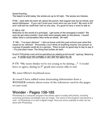
LITTLEWONDERBLOWERINTAKE GUARD ASSYFIGURE 121712139108431146579111058ITEM123PART NO.DESCRIPTION4166183LABEL-INTAKE GUARD4165218.7ASSY-GUARD INTAKE64123-54BLT-HEX 5/16-18X.7564123-69BLT-5/16-18 X 1 1/2(USED ON 9570 MODEL 64123-12764123-267NUT-FL NYLON LOCK 5/16-18NUT 5/16-18INTAKE PANEL-CENTERBLT-HEX 7/16-20 x 1-3/4 GR8(USED ON 9270 MODELS)BLT-HEX 3/8-24X1-3/4 GR8(USED ON 9390 AND 9400 MODELS)BLT-HEX 3/8-24 X 2.5 GR 8(USED ON 9570 MODELS64118416673041667314166992WLDMT-FAN 7 BLADE 2.75(USED ON 9270 MODELS)WLDMT-FAN 9 BL(USED ON 9390 AND 9400 MODELS)WLDMT-FAN, 9BL 3.50(USED ON 9570 MODELS)19KEY 1/4 X 2 SQKEY 1/4 X 1-3/4 SQ(USED ON 9570 MODELS)164164-1364164-40ITEMPART NO.DESCRIPTIONQTY10416342741634244166437PLUG-FAN 7/16 X 11(USED ON 9270 MODELS)PLUG-FAN 3/8 X 1.0(USED ON 9390 AND 9400 MODELS)PLUG-FAN 18 VAN(USED ON 9570 MODELS)1141651694165170SPACER-FAN .531(USED ON 9270, 9390, & 9400 MODELS)SPACER-FAN 1.24(USED ON 9570 MODEL)124166997RING-INLET OFFSET(USED ON 9570 MODEL ONLY)11333030-09BUSHING-.72 X .875(USED ON 9570 MODEL ONLY)415
LITTLEWONDERBLOWERENGINE ASSYFIGURE 26425 23245 27103293116881632833 26 71616192124239153019291611 191716201221182013121411 122ITEM1PART NO.DESCRIPTIONQTY64229-02LOCKNUT-NYL 5/16-18(QTY 6 ON 9570 MODEL)64141-6NUT 5/16-184166074ENG-HONDA GX270(USED ON 9270-02 MODEL)4165990ENG-SUBARU EX27(USED ON 9270-03 MODEL)4166075ENG-HONDA GX390(USED ON 9390 MODEL)4165993ENG-SUBARU EX40(USED ON 9400 MODEL)4166420ENG-ENGINE-VANGUARD 18(USED ON 9570 MODEL)4174173ENG-ENGINE-KOHLER CH395(USED ON 9270-06 MODEL)4166778S-LEVER W/ GRIP(INCLUDES ITEM 6)44166170-01CABLE-THROTTLE(USED ON HONDA ENGINES)4166170-02CABLE-THROTTLE(USED ON SUBARU ENGINES)4166170-03CABLE-THROTTLE(USED ON VANGUARD ENGINES)4166170-04CABLE-THROTTLE(USED ON KOHLER 6615234516GRIP-GRIP-1/4X1X5 LEVERS-HANDLE UPPER W/ GRIPS(INCLUDES ITEM 8 QTY 2)GRIP-1-1/4 X 14BLT-HEX 1/4-20X1.75CABLE-PRE 12324252627282930313233PART NO.DESCRIPTION4164204WHEEL-4.10/3.50 X 664144-36SNAP RING.6254164192-01SPACER-PDR MTL 35X1.0X.254164178AXLE4167557.10HANDLE LOWER(USED ON 9270, 9390, 9400 MODELS)4164591.10HANDLE-LOWER(USED ON 9570 MODEL)64163-55WASHER-5/16 FLAT(QTY 6 ON 9570 MODEL)4164588.7DECK-ENGINE,BLR LG4165895.10BRACE-LOWER HANDLE(USED ON 9570 MODEL ONLY)64123-61BLT-HEX 5/16-18X1-3/4(QTY 6 ON 9570 MODEL)4164204-01BEARING-WHL64268-02NUT-FL NYLON LOCK 5/16-1864262-009BLT-FLGHD 5/16-18X1-1/2(QTY 2 ON 9570 MODEL)64262-019BLT-FLG HD 5/16-18 X 1-3/4(QTY 2 ON 9570 MODEL)64229-01NUT-NYLON LOCK 1/4-204165854WASHER- UHMW 4139-26BLT-WLF 10-32 X 5/864188-65PIN CLEVIS 1/4X.6264268-03NUT-FL NYLON LOCK 3/8-1664018-5BLT-CRG 3/8-16X1-3/464123-98BLT-HEX R-HAIRPIN .08X1.19QTY222111411444412112144111
LITTLEWONDERBLOWERHOUSING ASSEMBLYFIGURE 3USED ON 9570 MODEL 122232425262728293031PART 5192416661441666154166324-0241661768DESCRIPTIONNUT 5/16-18S-HOUSING LG BLOWERLABEL-BLOWER SIDELABEL-WARNING/DANGERBLT-WLF 5/16-24 X BEL-READ MANUALLABEL-SCROLLDEFLECTOR-SIDEBLT-TDFM 10-32X1/2DEFLECTOR-INTHANDLE-DEFLECTORNUT-NYLON LOCK 3/8-16BLT-HEX 3/8-16 X 5-1/2BRKT-FRT WHLWHEEL-4.10/3.50X4SLEEVE-WHEELSPACER-FRT WHL BRKTBEARING-WHEELBEARING-FL PLASTIC .31 IDSPACER-ENG HOUSINGBLT-HEX 1/4-20 X 2-1/4WSHR .328X.75X14 GAPIVOT-DEFLECTOR,OUTERLINK-MASTER #43CABLE-PUSH,POST 211112334ITEM32333427313233PART NO.416619564229-014166618DESCRIPTIONKNOB-1/4 FEMALENUT-NYLON LOCK 1/4-20CHAIN-DEFLECTORITEMS 35-44 USED ON 9570 MODEL ONLY3564205-021BLT-M6 1X163664025-02NUT-HEX 5/16-183764152-27SCREW-SP 1/4-20 X T-MUFFLER B&S4364018-14BLT-CRG 5/16-18 X 1 1/44464205-001BLT-M8 1.25 X 20QTY1211141111411*NOT ILLUSTRATED17
5 YEAR LIMITED SERVICE ANDWARRANTY POLICYFOR LITTLE WONDER BLOWERSAll Little Wonder Blowers are warranted against defects in material and workmanship for a period of five (5) yearsfrom the date of purchase, under the following terms and conditions.LITTLE WONDER will repair or replace, at its option, any part or parts of the product found to be defective in material or workmanship during the warranty period. Warranty repairs and replacements will be made without chargefor parts or labor. All parts replaced under warranty will be considered as part of the original product, and anywarranty on the replaced parts will expire coincident with the original product warranty. If you think your LITTLEWONDER BLOWER is defective in material or workmanship, you must return it to a registered dealer with a validsales receipt or to our factory at 1028 Street Rd., Southampton, PA 18966. Transportation charges to ship yourproduct to us or a registered dealer must be borne by you.Engines for all gasoline powered products are warranted separately by the engine manufacturer. Therefore, thereare no warranties made, expressed or implied, for engines for gasoline powered products by LITTLE WONDER.LITTLE WONDER assumes no responsibility in the event that the product was not assembled or used in compliance with any assembly, care, safety or operating instructions contained in the Owner’s Manual or informationaccompanying the product. This limited warranty does not cover damages or defects due to normal wear andtear, lack of reasonable and proper maintenance, failure to follow operating instructions or Owner’s Manual,misuse, lack of proper storage or accidents, nor does it cover routine maintenance parts and service. This limitedwarranty does not cover any defects due to repairs or alterations made to the product made by anyone other thanLITTLE WONDER or its registered dealers.You must maintain your LITTLE WONDER Blower by following the maintenance procedures described in theowner’s manual. Such routine maintenance, whether performed by you or a registered dealer, is at your expense.LITTLE WONDER MAKES NO EXPRESS OR IMPLIED WARRANTIES REPRESENTATIONS OR PROMISESEXCEPT THOSE CONTAINED HEREIN. THERE ARE NO OTHER WARRANTIES, INCLUDING WARRANTIESOF MERCHANTABILITY AND FITNESS FOR A PARTICULAR PURPOSE. ALL WARRANTIES OTHER THANTHE EXPRESS WARRANTY SET FORTH ABOVE ARE SPECIFICALLY DISCLAIMED. THE DURATION OF ANYIMPLIED WARRANTY, INCLUDING MERCHANTABILITY AND FITNESS FOR A PARTICULAR PURPOSE, ISLIMITED TO THE DURATION OF THIS WRITTEN LIMITED WARRANTY. LITTLE WONDER DISCLAIMS ALLLIABILITY FOR INDIRECT, INCIDENTAL AND/OR CONSEQUENTIAL DAMAGES IN CONNECTION WITH THEUSE OF THE LITTLE WONDER BLOWER PRODUCTS COVERED BY THIS WARRANTY. SOME STATES DONOT ALLOW LIMITATIONS ON HOW LONG AN IMPLIED WARRANTY LASTS AND/OR DO NOT ALLOW THEEXCLUSION OR LIMITATION OF INCIDENTAL OR CONSEQUENTIA
WONDER BLOWER MODEL NUMBER: This number appears on sales literature, technical manuals and price lists. SERIAL NUMBER: This number appears only on your unit. It contains the model number fol-lowed consecutively by the serial number. Use this number when ordering parts or seeking war-ranty information. Schiller Grounds Care, Inc. 1028 Street Road