Transcription
Tiffin Instrument Panel SpecificationVersion 8.0( March 3, 2010 )This document contains information, which is confidential and proprietary to Medallion Instrumentation Systems, LLC.
Tiffin GDIG Based Gauge System SpecificationConfidentialREVISION HISTORYREVAUTHORDescription of ChangeDate1.0THOriginal Draft12/16/092.0THMark ups and corrections12/17/093.0THAdded more corrections and detail01/22/104.0SRAdded Icon Graphics supplied by Customer01/26/10Added Graphical Display Requirements provided by customer and5.0SRupdated to capture Customer Input from Engineering01/28/10Teleconference.Added SAE J1455 and note to section 4 References per Medallion6.0SS7.0SRDocumented Back Light Color Selection and added new Icons02/15/108.0SRUpdated message set and inserted latest panel illustrations03/03/10requirement ISO-P-02802/02/10APPROVAL SIGNATURESProgram ManagerDateProduct ManagerDateAuthor of Current VersionDateRevision 8Page 2 of 2103/03/2010
Tiffin GDIG Based Gauge System SpecificationConfidential1.PurposeThe purpose of this document is to specify the operation of the Tiffin Instrument Panel.2.ScopeThis document applies to the Tiffin MY2011 Power Glide Application using Cummins ISL and ISC engines.3.TimingThis product would be introduced to production at Tiffin at the Model Year Change Over currently scheduledfor the week of March 22nd, 2010.4.ReferencesSAEJ1939SAEJ1455MedallionM3 Peripheral Communications ProtocolNote: Unless otherwise noted, specifications referenced in this design record apply at the revision level ineffect on the original date of issuance of the design record.5.DefinitionsLINAnalog Instrument Data BusIPAInstrument Panel AssemblyGDIGGraphical Data Interface GaugeECUEngine Control UnitRevision 8Page 3 of 2103/03/2010
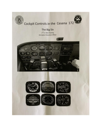
Tiffin GDIG Based Gauge System SpecificationConfidential6.System Definition6.1.SYSTEM DESCRIPTION AND CONTENTEach Tiffin Instrument Panel Assembly shall consist of 6 components:6.2. A Chameleon Warning Lamp Assembly A 5” GDIG Speedometer with a Graphical Info Center A 5” 4N1 Gauge A 5” 3N1 Gauge A Panel HarnessingPANEL OPTIONSDESCRIPTIONPART NUMBERMY2010 IPA4571-11037-01MY2011 IPA4571-11039-01ILLUSTRATIONPanel Part Number IdentifierTable - 1Revision 8Page 4 of 2103/03/2010
Tiffin GDIG Based Gauge System SpecificationConfidential6.3.CHAMELEON WARNING LAMP ASSEMBLY DESCRIPTIONThe GDIG interfaces with a Chameleon module via the LIN bus to indicate vehicle warningconditions to the operator. The Chameleon Module features LED indicators that illuminatevia messages on the J1939 bus, direct inputs to the GDIG, or direct inputs to the ChameleonModule itself. The following indicators are OLALARMJ3-1ACTIVE HIGHON SOLID51RIGHT TURNGREENDIRECT2STOP ENGINEREDJ-1939 DM-1PGN: 65226SPN 623ON SOLID33CHECK ENGINEAMBERJ-1939 DM-1PGN: 65226SPN 624ON SOLID44COOLANT TEMPREDJ-1939DM1ON SOLIDNONE5DEF LEVELAMBERJ-1939PGN: 65110SPN: 5245ON SOLIDNONE6MILAMBERJ-1939 DM-1PGN: 65226SPN 1213ON SOLIDNONE7WAIT TO STARTAMBERJ-1939PGN: 65252SPN 1081ON SOLID48SPARE9OIL PRESSUREREDJ-1939DM1ON SOLIDNONEACTIVE LOWON SOLIDNONELOW SPEED10PARK BRAKEREDDIRECTJ2-52FLASH @ 0.3S 2 MPHOPEN ANDFLASH @ 0.3S2IGN OFFTABLE CONTINUED ON NEXT PAGERevision 8Page 5 of 2103/03/2010
ConfidentialICON11NAMEABSTiffin GDIG Based Gauge System OLALARMON SOLID4ON SOLID1ON SOLIDNONEACTIVE HIGHON SOLID5SPN 3697ON SOLID4SPN 3697FLASHSPN 3698ON SOLIDNONEPGN: 61441SPN 1793J-1939ON @ 65 PSI12LOW AIRREDGDIGOFF @ 72 PSION @ 11.5 V13LOW VOLTAGEREDJ-1939OFF @ 13.2 V14LEFT TURNGREENDIRECT15DPF STATUSAMBERJ-1939J3-2HOT IRECTJ3-419SPAREDIRECTJ3-520HIGH BEAMBLUEDIRECTJ3-6ACTIVE HIGHON SOLIDNONE21JACKS DOWNREDDIRECTJ3-7ACTIVE LOWON SOLID422SPAREDIRECTJ3-8ON SOLIDNONEON SOLID4ON WITH23CHECK INFOAMBERDIGACTIVEWARNING24CHECK TRANSAMBERJ-1939DM1Chameleon Warning Lamp DescriptionsTable - 2Revision 8Page 6 of 2103/03/2010
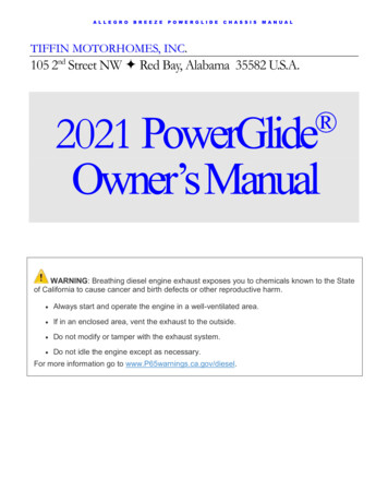
ConfidentialTiffin GDIG Based Gauge System SpecificationChameleon Warning Lamp LocationsFigure - 16.4.GENERAL GAUGE STYLING REQUIREMENTSFEATUREREQUIREMENTDial GraphicCustom TiffinGraphic Back Light ColorAmberBezel FinishChromePointer TypeStandardPointer ColorRed LisaPointer CapBlack ButtonPointer Back Light ColorRedGeneral Styling RequirementsTable - 3Revision 8Page 7 of 2103/03/2010
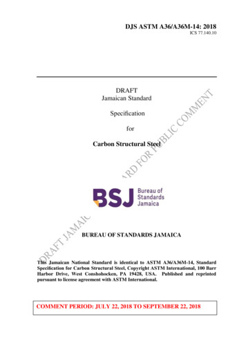
Tiffin GDIG Based Gauge System SpecificationConfidential6.5.SPEEDOMETER DESCRIPTIONGDIG SpeedometerFigure - 26.5.1.DIG RequirementThe Speedometer is a GDIG and acts as the instrument system controller for the IPA.6.5.2.Speedometer ScaleThe Speedometer shall have a zero to 120 scale with units displayed as dead fronted icons.6.5.3.Button DescriptionThe Speedometer shall have integral buttons for controlling the LCD6.5.4.Required Dead Front IconsNAMEGRAPHICCOLORSOURCESEAT BELTREDTIMEDLOW FUELAMBERGDIGSIGNALON @ IGNCONTROLALARM30 SECNONEON SOLIDNONEON SOLIDNONEON @ 12.5%OFF@ 18%CRUISEGREENJ-1939WATER IN FUELAMBERJ-1939ON SOLID4MPHAMBERGDIGON SOLIDNONEkm/hAMBERGDIGON SOLIDNONERevision 8Page 8 of 21SPN52703/03/2010
Confidential6.5.5.Tiffin GDIG Based Gauge System SpecificationDriver’s Information Center DescriptionThe Speedometer shall include a Graphical Drivers Information Center.The functionality of the Driver’s Information Center can be broken down into 5 categories:1. A Pre Drive Check List2. A main or default screen in which the following information is displayed:Main Odometer Data BlockTrip Odometer Data Block (Trip1 and Trip 2 can share a data block)Gear Attained Data Block3. The display of user selectable digital data:DATASOURCEFORMATBATTERY VOLTAGEJ-1939XX.X VOLTSENGINE HOURSJ-1939XX,XXX.XX HOURSENGINE RPMJ-1939XXXX RPMINSTANTANEOUSFUEL ECONOMYJ-1939XX.X MPGAVERAGEFUEL ECONOMYDIGCALCULATEDXX.X MPGTRANSMISSIONTEMPERATUREJ-1939XXX.Xº (F/C)ENGINE LOADJ-1939XX %DIGXX,XXX.XX HOURSGENERATOR HOURSUser Selectable Digital DataTable – 4Revision 8Page 9 of 2103/03/2010
Tiffin GDIG Based Gauge System SpecificationConfidential4. There shall be pop up warning messages for the following conditions:ALARM CONDITIONSOURCE“LOW VOLTAGE”J-1939“ATC Warning”J-1939“TRANSMISSION TEMP”J-1939‘COMMUNICATION ERROR”J-1939“TURN SIGNAL ON”DIG“GENERATOR LOW FUEL”DIGNOTESPGN: 61441 SPN: 1438Engine, Trans, or ABSTurn Signal “On” 1 Mile TraveledGenerator “On” Fuel 20%Info Center Pop Up Warning MessagesTable – 5Notes:1) Each of the above alarms will turn on the “Check Info” Warning Lamp.2) Each of the above alarms will activate audible alarm 4.3) Each of the above alarms require user acknowledgement to clear5. There shall be utility screens to support the following functions:FUNCTIONFORMATENGLISHORMETRICUNITS SELECTIONIDLE SPEED ADJUSTMENTCHASSIS DIAGNOSTICS:ABS FAULT CODESENGINE FAULT CODESTRANSMISSION FAULT CODESXXXX RPMSPN: XXXXFMI:XXIPA DIAGNOSTICS:GAUGE TEST ROUTINEDISPLAY OF INPUT SIGNAL VALUESWARNING BAR TEST ROUTINEDISPLAY TEST ROUTINEODOMETER SERVICE ROUTINEUtility/Set Up ScreensTable – 6Revision 8Page 10 of 2103/03/2010
Confidential6.5.6.Tiffin GDIG Based Gauge System SpecificationPre-Drive Checklist Description The Pre-Drive Checklist will be displayed at key on. Each item in the list must be acknowledged by the operator. Edit FunctionThe check list items actually displayed at key on shall be user selectable from aMaster List of items. The Master Pre-Drive Checklist Items include: JACKS / AIR LEVELER UP CHECK TOW VEHICLE TIRE PRESSURE ENGINE MAINTAINANCE DISCONNECT POWER DISCONNECT WATER DISCONNECT SEWER BAY DOORS CLOSED SHOWER DOOR LOCKED ROOF VENTS CLOSED AWINING ARMS LOCKED COUNTERTOP CLEAR ALL DOORS LOCKED DRAWERS LATCHED APPLIANCES SECURED SLIDES IN AND SECURED WINDOWS CLOSED CB RADIO ONRevision 8Page 11 of 2103/03/2010
Tiffin GDIG Based Gauge System SpecificationConfidential6.5.7.Odometer Operation The odometer is to be displayed as 0 to 999,999 without leading zeros and withno tenths displayed. The GDIG shall calculate and maintain the odometer value. The odometer accuracy shall exceed the requirements of SAE J-1226. The trip odometer is to be displayed, on command, as 0.0 to 9999.9 withoutleading zeros. The odometer and trip odometer are to be displayed in English or metric units ascommanded. The accumulated odometer value must be stored at least every kilometer. In the event of a power failure, the odometer value must be saved in memory andretrievable for at least five years. In the event of an engine controller failure (no data on the data bus), theaccumulated odometer value is to be stored and not incremented until a validodometer value or increment rate is received from the engine. At this time theodometer should begin incrementing the stored value at the rate dictated by theengine. The odometer should ignore any message that would decrease the storedodometer value or increase the stored value in more than 25Km increments. Revision 8The design life of the odometer is to be at least 2 million miles.Page 12 of 2103/03/2010
Tiffin GDIG Based Gauge System SpecificationConfidential6.5.8.Wake UpThe GDIG shall wake up when the voltage at pin-3 is increased to a logic high level.On the Tiffin Chassis the Wake Up signal shall be provided by the MUX System so thatinstrument system can wake up, regardless of the state of the Ignition Switch, to support thefollowing features: Generator Hour Meter Generator Low Fuel Alarm Turn Signal On Alarm6.5.9.Generator Support1) The MUX System will transmit generator status as follows:PGNDATA PAGEPRIORITYDATA LENGTHREP RATE65280058 Bytes1 Sec, update on change, max 40/secGenerator StatusByte 1, Bit 30 OFF1 ONSource 2092) The GDIG will track, save and display accumulated generator hours.3) The GDIG shall illuminate the Check Info warning lamp, display a warning message inthe Drivers Information Center, and actuate the Alarm-4 when the fuel level falls below20% while the generator is running.6.5.10. Turn Signal Support1) The MUX System will transmit Turn Signal status as follows:PGN65280DATA PAGE0PRIORITY5DATA LENGTH 8 BytesREP RATE1 Sec, update on change, max 40/secTurn Signal RHTurn Signal LHByte 1, Bit 5Byte 1, Bit 60 OFF0 OFF1 ON1 ONSource 210Source 2102) When the GDIG senses that either turn signal has been left on for a distance equal to orgreater than 1 mile The GDIG shall illuminate the Check Info warning lamp, display awarning message in the Drivers Information Center, and actuate the Alarm-4Revision 8Page 13 of 2103/03/2010
ConfidentialTiffin GDIG Based Gauge System Specification6.5.11. Alarm DescriptionThe DIG shall provide an active low output capable of driving an external audio transduceras described below:Alarm Priority1234Tone900 Hz900 Hz900 Hz900 HzPulse Width-160 milliseconds160 milliseconds750 millisecondsRepetition RateContinuous880 milliseconds2.2 secondsOnce No RepeatAlarm DefinitionTable – 7Alarm 1 is the highest priority alarm and 4 is the lowest. If while an alarm is active, ahigher priority alarm becomes active, the DIG will detect the change and sound the alarmthat has the higher priority.The external audio transducer shall be part of the Medallion harness.Revision 8Page 14 of 2103/03/2010
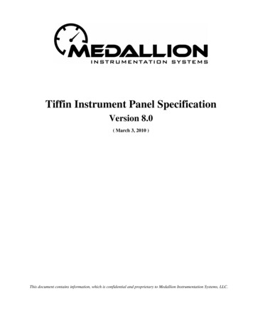
Tiffin GDIG Based Gauge System SpecificationConfidential6.6.3N1 GAUGE DESCRIPTION6.6.1.3N1 Gauge Illustration3N1 GaugeFigure – 36.6.2.Revision 8TachometerLabel:RPMDisplayed Range:0 – 3000 RPMRed Zone:NoneData Source:Engine ECUData Type:J1939Source Address:0SPN:190PGN:61444Page 15 of 2103/03/2010
Tiffin GDIG Based Gauge System SpecificationConfidential6.6.3.Main Fuel Tank LevelLabel:FUELDisplayed Range:E–FRed Zone:Below 15%Data Source:Analog inputData Type:Resistive (33-240Ω)DIG Input Pin:16PIN-10Fuel Table:6.6.4.Generator Fuel LevelThe Fuel Level Dial Graphic has a Dual Scale to indicate the available fuelremaining for the Generator.LabelGENEmpty on The Generator Fuel Scale equates to 15% on the Main Fuel ScaleRed Zone:Revision 8Below 25%Page 16 of 2103/03/2010
Tiffin GDIG Based Gauge System SpecificationConfidential6.6.5.DEFIndicates the current exhaust fluid level available6.7.LabelDEFDisplayed Range:E–FRed Zone:12.5%Data Source:Engine ECUData Type:J1939Source Address:0SPN:1761PGN:651104N1 GAUGE DESCRIPTION6.7.1.4N1 Gauge Illustration4N1 GaugeFigure – 4Revision 8Page 17 of 2103/03/2010
Tiffin GDIG Based Gauge System evision 8Front AirLabel:FRONT AIRDisplayed Range:0-150 psiData Source:Analog inputData Type:Voltage (0.5 – 4.5V) (0 – 150 psi)Input Pin:DIG 16PIN-12Rear AirLabel:Displayed Range:Data Source:Data Type:Input Pin:REAR AIR0-150 psiAnalog inputVoltage (0.5 – 4.5V) (0 – 150 psi)DIG 16PIN-11Oil PressureLabel:Displayed Range:Data Source:Data Type:Source Address:SPN:PGN:OIL PRESS0 – 120 PSIEngine ECUJ1939010065263Coolant TemperatureLabel:Displayed Range:Data Source:Data Type:Source Address:SPN:PGN:COOLANT145 – 245 FEngine ECUJ1939011065262Page 18 of 2103/03/2010
Tiffin GDIG Based Gauge System SpecificationConfidential6.8.AUXILLARY GAUGE SUPPORT6.8.1.Displayed Range:8-18 VoltsData Source:Engine ECUData Type:J1939Source Address:0SPN:158PGN:652716.8.2.Transmission Oil TemperatureDisplayed Range:106-325 FData Source:Transmission ECUData Type:J1939Source Address:3SPN:177PGN:652726.8.3.Revision 8VoltmeterBoost PressureDisplayed Range:0-75 psiData Source:Engine ECUData Type:J1939Source Address:0SPN:102PGN:65270Page 19 of 2103/03/2010
ConfidentialTiffin GDIG Based Gauge System SpecificationAPPENDIX AMAIN HARNESS DETAILPlug NumberMates with:Connector TypeConnector Part NumberTerminalLockSeal0ChassisConnector InformationSignal DescriptionCA-1939-HCA-1939-LBatt V DashBatt V- Main GND CRIgnition VMM Frt OPPark Brake SigHeadlmps HB PSLH Turn LampsRH Turn LampsService Brake SigPNL Lmp Ctrl PWMFuel LevelJacks DownCruise ON/OFFCruise setCruise ResumeCruise CancelBuzzerSensor 5vdcFront AirRear Air123DIGChameleon ChameleonMOLEX 16 MOLEX 8TYCO 1033472-1606 33472-0806 770580-1Connector33012-1002 33012-1002 794407-1TBD4Front AirDelphi 3135322441532626715452678153053515Rear AirDelphi zerPiezoSignal InformationPin 23236"6"1026"36"54Revision 8Page 20 of 2103/03/2010
ConfidentialAPPENDIX BRevision 8Tiffin GDIG Based Gauge System SpecificationTIFFIN J-1939 DATA SUMMARYPage 21 of 2103/03/2010
Confidential Tiffin GDIG Based Gauge System Specification Revision 8 Page 2 of 21 03/03/2010 REVISION HISTORY REV AUTHOR Description of Change Date 1.0 TH Original Draft 12/16/09