Transcription
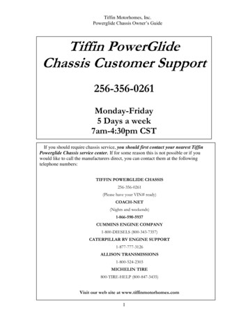
Tiffin Motorhomes, Inc.Powerglide Chassis Owner’s GuideTiffin PowerGlideChassis Customer Support256-356-0261Monday-Friday5 Days a week7am-4:30pm CSTIf you should require chassis service, you should first contact your nearest TiffinPowerglide Chassis service center. If for some reason this is not possible or if youwould like to call the manufacturers direct, you can contact them at the followingtelephone numbers:TIFFIN POWERGLIDE CHASSIS256-356-0261(Please have your VIN# ready)COACH-NET(Nights and weekends)1-866-590-5937CUMMINS ENGINE COMPANY1-800-DIESELS (800-343-7357)CATERPILLAR RV ENGINE SUPPORT1-877-777-3126ALLISON TRANSMISSIONS1-800-524-2303MICHELIN TIRE800-TIRE-HELP (800-847-3435)Visit our web site at www.tiffinmotorhomes.com1
Tiffin Motorhomes, Inc.Powerglide Chassis Owner’s GuideTIRE CARE What is the most important component of tire care? TIRE PRESSUREo Why?Improved RideImproved Tire WearImproved Road HandlingImproved BrakingTIRE CAREMaintaining the proper tire inflation pressure is the most important thing you can do tomaximize the life of your tires. An under inflated tire will build up excessive heat that may gobeyond the prescribed limits of endurance of the rubber and the radial cords. Over inflation willreduce the tire’s foot print on the road, reducing the traction, braking capacity, and handling ofyour vehicle. An over inflated tire will also cause a harsh ride, uneven tire wear, and will be moresusceptible to impact damage.Keep in mind that the pressure rating on the side wall of your tire is the maximum pressure forthat tire. This is not necessarily the correct pressure for the tires when installed on your vehicle.Maintaining the correct tire pressure for your vehicle’s loaded weight is extremely important and mustbe a part of regular vehicle maintenance.2
Tiffin Motorhomes, Inc.Powerglide Chassis Owner’s GuideCorrect Tire Pressure How to determine the correct pressure Weigh each wheel position Set tire pressure according to chart* This Chart Shows Cold Inflation Pressures295/80 R22.5 LRH Energy XZA2Load per Wheel-endMaxLoad perTirePSI KPA 4,8004,9805,2405,4405,6205,8803,150To determine the correct air pressure for your tires, load your motor home as you wouldnormally travel, including water and fuel. Go to a truck scale as found at most major truck stopsand weigh each wheel position independently, with driver and passenger(s) in the vehicle asdescribed in the Michelin Recreational Vehicle Tire Guide (MWL43146 Rev. 6/07) todetermine the correct air pressure for the weight on each wheel position. Then use the charts inthe guide and adjust the pressure accordingly when the tires are cool or have not been driven formore than one mile. You may call 1-800-847-3435 for a copy of the Michelin RecreationalVehicle Tire Guide.NOTE: Never reduce the air pressure in a hot tire.REMEMBER: For control of your RV, it is critical that the tire pressure be the same on bothsides of the axle.3
Tiffin Motorhomes, Inc.Powerglide Chassis Owner’s GuideAllison Transmission Operation Normal driving—best fuel economyo Select ―D‖ and ―Mode On‖ Performanceo ―Mode Off‖o For mountain driving select lower gears to maintain 2000 engine RPM Hill climbing on hot dayso Keep RPMs high to cool engineDriving Tips with the Allison MD3060 3000MH Transmission:The points at which shifts occur depend upon predetermined speeds and other operatingconditions. A transmission ―shift calibration‖ includes several sets of shift points which may beused according to current or anticipated operating conditions, such as engine or transmissionfluid temperature. Shift schedules may be changed using the MODE button.The transmission control module (TCM) includes the capacity for two separate and distinct shiftcalibrations, one for use in ―Primary Mode‖ of operation and one in ―Secondary Mode.‖Primary – This shift schedule is typically used for all normal vehicle operations.Secondary – This is an alternate shift schedule that the TCM uses upon request. This isoperator-controlled using the MODE button.When you are driving under normal road conditions, the DRIVE mode is recommended for thebest performance and fuel economy. The MODE switch should be set to ON for economymode, but MODE off should be used when climbing hills and when extra performance isrequired.The display screen on the shift control pad will indicate the highest selected gear for thetransmission. When mountainous or up and down terrain conditions are encountered, youshould manually select a lower gear, preferably lower than 5th gear, and turn OFF the modeswitch. This can be done at any road speed by pressing the down arrow repeatedly until thedesired gear is indicated in the window of the shifter pad and then pressing the MODE button.When your road speed decreases to a safe point, the transmission will downshift at a higherRPM than normal. This will decrease the use of overdrive while pulling hills, which can result inexcessive heat build-up in the transmission, and it keeps the engine operating at peak horsepower and performance.When ascending a grade, maintain engine speed to within 400-500 RPM of governed enginespeed. Governed speed will be 2000-2200 RPM depending on your engine model. Road speedmay decrease, but the engine will be at its peak in the power curve.4
Tiffin Motorhomes, Inc.Powerglide Chassis Owner’s GuideIt is especially pertinent to monitor your water temperature gauge when climbing hills. Keep inmind; it is not uncommon for the temperature to rise, especially in hot weather. If the gaugereaches the end zone or if the temperature warning light on the gauge panel should come on,reduce your road speed and shift to the next lower gear and keep your tachometer within 500RPM of engine governed speed. In many cases this will stabilize the water temperature. If thetemperature gauge continues to rise, pull over to the side of the road and shift the transmissioninto neutral. Bring the engine RPM to 1,700—2,000 RPM until the temperature drops down intothe normal range. This should occur in a relatively short period of time. If the temperature gaugedoes not begin to drop and stays in the red zone or continues to rise, shut down the engine andallow it to cool. After the engine is allowed to cool, check the fluid level in the reservoir and adda 50/50 coolant and water mixture if needed.A good ―rule of thumb‖ for descending grades is to never use a higher gear than was used toclimb the same or similar grade. Try to keep the engine within 500 RPM of governed speed. Thiswill give the best engine braking and reduce the need to use the service brakes. Select a gear thatwill keep you at a safe speed with minimal brake application. Never ride your brakes whendescending a grade since excessive brake heat will build up and your brakes could fade leavingyou with little or no braking power.If your vehicle is equipped with an exhaust brake, this will also assist in slowing your vehicle ona downhill grade. With the exhaust brake switch in the ON position, when your foot is releasedfrom the accelerator, the transmission select number changes to ―2.‖ The exhaust brake willengage and the transmission will begin to down shift as soon as road and engine speed will safelyallow. This will produce a slowing effect and will remain engaged until either the exhaust brakeswitch is turned off, the accelerator is depressed, or the transmission shifts to second gear. Ifyour initial speed is high, you may have to step on the brake to slow the vehicle before thetransmission will down-shift from 6th gear to 5th gear. This is normal.Always select (N) neutral on the transmission shift pad prior to turning off the vehicle engine.5
Tiffin Motorhomes, Inc.Powerglide Chassis Owner’s GuideAllison TransmissionFluid Level Check Be sure transmission is at operating temperature (140 to 220 F) Vehicle is parked on level ground Transmission in neutral and engine at idle Wait until vehicle has been stationary for two minutes Simultaneously press the up and down arrow keys Display indicates – OL-―OL followed by ―OK‖ indicates good oil level-―OL followed by ―HI‖ followed by number indicates quarts overfilled-―OL followed by ―LO‖ followed by number indicates quarts under-filled-―OL followed by ―--‖ proper conditions have not been met6
Tiffin Motorhomes, Inc.Powerglide Chassis Owner’s GuideBrake SystemRear BrakesAutomatic Slack Adjuster Front brakes are 17” air applied disc Rear brakes double as parking brake -Park brakes are spring applied-Two large 16.5 x 7‖ drum brakes-Park brake remains applied even if air pressure is lostIf air pressure is lost- A buzzer and warning lamp will alert youChassis is equipped with automatic slack adjusters-No brake adjustment requiredThe rear brakes on the PowerGlide chassis are also used as the parking brakes. This providesyou the holding power of two large drum brakes to prevent your coach from rolling even whenfully loaded on a 20% grade.A decrease in air pressure will not cause an immediate loss of brakes. If a leak develops in the airsystem while driving (at approximately 60 to 65 PSI) you will be alerted via a light on theinstrument panel and an audible alarm. As you apply the brakes, the air supply holding the parkbrakes in the released position will gradually be depleted. When fully depleted (approximately 40PSI to 45 PSI) the rear brakes will set. This allows you sufficient time to pull over to the side ofthe road.NOTE: (The rear brakes have dual chambers—one for the service brakes and one forthe park brake. The service brakes are air applied and spring released. The park brake isspring applied and air released).The brake system is equipped with automatic slack adjusters that avoid the need to manuallyadjust your brakes. Each time you step on the brake pedal, if adjustment is needed, the adjusterswill take up the slack.7
Tiffin Motorhomes, Inc.Powerglide Chassis Owner’s GuideCompressed Air SystemTank DrainsThe compressed air system is comprised of two air storage tanks. The primary tank storesand supplies air for the rear brakes, the secondary tank stores and supplies air for the frontbrakes.When air is compressed it becomes hot. As it cools condensed moisture forms in thesystem. The air system is equipped with an air dryer to remove most of this moisture. Thedryer has an automatic moisture ejector that releases the trapped moisture back into theatmosphere. However some moisture will form in the system beyond the dryer, and makeits way into the storage tanks. As moisture collects in the primary and secondary tanks itdisplaces the area needed for air storage, thus requiring that the tanks be drained periodically.The air system is equipped with two air tank drains conveniently located in the left rearstorage compartment. One drain for the primary tank and one for the secondary tank.These drains should be opened daily for a few seconds to remove any moisture trapped inthe tanks.8
Tiffin Motorhomes, Inc.Powerglide Chassis Owner’s Guide.Air DryerThe Tiffin PowerGlide chassis air brake system features a Haldex Purest air dryer whichremoves the condensed moisture from compressed air. The air dryer is equipped with adesiccant cartridge that needs to be changed every 36 months. The dryer is located on the lefthand frame rail (behind the rear axle).WARNING: Air tanks should be bled of all pressure any time you performwork on the air system.9
Tiffin Motorhomes, Inc.Powerglide Chassis Owner’s GuideEngine CompressionBrakeProvides: Improved braking power Reduces the chance of overheating brakes on steep grades Works in conjunction with Allison electronic transmissions Compression brake allows for 3 or 6 cylinder useAll brakes will build up heat when being used due to friction—this is normal. However,excessive use of the brakes when descending a grade can result in excessive heat and can cause―brake fade‖ or a loss of braking power, even with disc brakes. The proper way to use yourbrakes is to go slowly enough that a fairly light occasional use of the brakes will keep your speedfrom increasing.NOTE: DO NOT maintain continual brake pedal pressure when descending a hill with anytype of brake system.Rather, down shift the transmission to slow the vehicle and make light, intermittent brakeapplications to control downhill speeds. By utilizing the transmission gears and CompressionBrake, continual use of the brakes will not be necessary. When using the transmission’s lowergears to slow the vehicle on hills, be careful not to exceed the governed speed of your engine. Ifengine-governed speed is exceeded, the transmission will shift up to the next range, rapidlyincreasing the speed of your vehicle. If you find that you are continually using the brakes tomaintain a safe speed and to keep the RPM within this range, slow the vehicle down evenfurther and shift the transmission to a lower gear.CAUTION: DO NOT USE the Compression Brake on wet roads, hazardous, or slipperyconditions. As with any motorized vehicle, practice safety when on the road.10
Tiffin Motorhomes, Inc.Powerglide Chassis Owner’s GuideScheduled MaintenanceSERVICE INTERVAL(Miles x 1,000)Daily 5 10 15 20Required Fluids, Lubricants, and ProceduresAir System:Air DryerAir IntakeXInspect for leaks and blockage of purge valveXInspect for blockageAir FilterXCheck restriction indicator - replace filter as needed (7)Primary Air Tank ReservoirXDrain condensation dailySecondary Air Tank ReservoirXDrain condensation dailyBrake Systems:ABS SensorsXClean sensors & adjust into hub rings. (1)Brake Pads, Rotors, Shoes & DrumsXInspect pads, shoes, rotors & drums for wear and cracks. (1)Slack AdjustersXInspect slack adjuster for proper adjustment & grease.Brake Hoses/Whips, Front & RearXInspect for leaks, & cracking.A/C Condenser FinsXInspect for blockage and wash clean every 10k or as neededCharge Air Cooler FinsXInspect for blockage and wash clean every 10k or as neededFan & Fan ShroudXInspect for blockage and cracks.Radiator Fins/GrillXInspect for blockage and wash clean every 10k or as neededRadiator Hoses & PipesXInspect for kinks, chaffing wear and leaks.Cooling Systems:Surge Tank CapXInspect for leaks dailySurge Tank Vent LinesXInspect for kinks and leaks dailyFan ClutchXInspect for correct alignmentFan Drive BeltXReplace fan belt.Fan Drive Shaft U-JointsXLubricate w/NGLI #2 greaseFan Gear BoxXChange fluid and inspect for leaks. (6)Electrical Systems:Rear Electrical CompartmentXCheck for loose fuses and cablesFront Electrical CompartmentXCheck for loose fuses and cablesGenerator CablesXCheck for loose red & black cables connected to generatorAlternator BeltBatteriesXCheck for correct tension and wearXCheck for loose lugs / remove any corrosion11
Tiffin Motorhomes, Inc.Powerglide Chassis Owner’s GuideScheduled MaintenanceSERVICE INTERVAL(Miles x 1,000)Daily 5 10 15 20Required Fluids, Lubricants, and ProceduresEngine Systems:Engine Drive Belt TensionXInspect belt & tension.Engine Oil FilterXReplace engine oil filter per engine manual (1)Engine OilXChange engine oil per engine manual (1)Exhaust Muffler & PipingXInspect for pinholes, rust and leaks.Diesel FuelAlways use ultra low sulfur fuel onlyFuel Tank Vent LinesXFuel Tank & LinesXInspect for "P" traps that may cause air locks and slow fillingInspect for leaks around fuel inlet nipples and hoses.Engine CoolantChange engine coolant per engine manualPrimary Fuel FilterXReplace fuel filter per engine manual (1)Secondary Fuel FilterXReplace fuel filter per engine manual (1)Steering Systems:Drag LinkXInspect castle nuts for looseness & lube rod ends w/NGLI #2 greaseSteering Gear ArmXInspect for looseness.Steering GearXInspect mount bolts for looseness & hydraulic hoses for leaks.Steering Gear PumpXInspect for hydraulic hose leaks at fittings.Steering Shaft U-JointsXInspect for loose fasteners & lube bearings w/NGLI #2.Steering Shaft BootXInspect for clearance between boot & shaft, lubricate w/ NGLI #2 grease.Suspension & Axles:Coach AlignmentXAlign coach as needed (4)Front Ride Height AdjustXAdjust to 9" side to side from bottom of air bag to top of air bag mount placeRear Ride Height AdjustXAdjust to 7" side to side from bottom of rail to centerline of axleRide Height Valve LinkagesXGrease linkage grommets w/D.A. Stewart Aqualube.Air Suspension BagsXInspect for leaks at fittings and inspect bags for leaks or cracksFront Axle BearingsXCheck fluid level through sight window, if low, repair leaks as necessary (1)Front Axle Tie Rods - InspectXInspect for loosenessFront Axle Tie Rods LubricateXLubricate W/NGLI # 2 greaseFront Axle King PinsXLubricate W/NGLI #2 greaseFront & Rear ShocksXRear Axle LubeWheel Lug TorqueInspect for leaks on shock tube, replace as neededXXInspect for leaks & check fluid level. Use synthetic oil only 75W90 (3)Re-torque all wheels nuts - Torque 450-500 lbs (2)12
Tiffin Motorhomes, Inc.Powerglide Chassis Owner’s GuideScheduled MaintenanceSERVICE INTERVAL(Miles x 1,000)Daily 5 10 15 20Required Fluids, Lubricants, and ProceduresSuspension & Axles:Automatic Slack AdjustersXLubricate W/NGLI #2 greaseSlack Adjuster Cam ShaftsXLubricate W/NGLI #2 greaseSlack Adjuster Clevis PinsXInspect for wear in clevis pin and cotter pins. Replace as necessaryTransmission & Driveline:Drive ShaftXInspect u-joints & safety strap for loose bolts & wear, lubricate w/NGLI #2 greaseTransmission FluidReplace fluid at 150,000 miles or 48 months whichever occurs first. (5)Transmission FiltersReplace filters at 75,000 miles or 36 months whichever occurs first. (5)(1) Replace / inspect at stated mileage interval or every 12 months whichever occurs first(2) Re-torque all wheel nuts after the first 100 miles, then every 10K miles thereafter.(3) Factory filled with synthetic oil. Do not mix with mineral oils.(4) For best tire life and handling, alignment of front axle is recommended every 15K miles.(5) Factory filled with TranSynd. To maintain these service intervals, fluid must not be mixed with Dexron or other fluids.(6) Total fluid capacity is 24oz. Use only synthetic 75W90 oil.(7) Replace filter when indicator shows 25 inches or every two years whichever occurs first.13
Tiffin Motorhomes, Inc.Powerglide Chassis Owner’s GuideLubrication Points14
Tiffin Motorhomes, Inc.Powerglide Chassis Owner’s GuideLubrication Points15
Tiffin Motorhomes, Inc.Powerglide Chassis Owner’s GuideLubrication Points16
Tiffin Motorhomes, Inc.Powerglide Chassis Owner’s GuideLubrication Points17
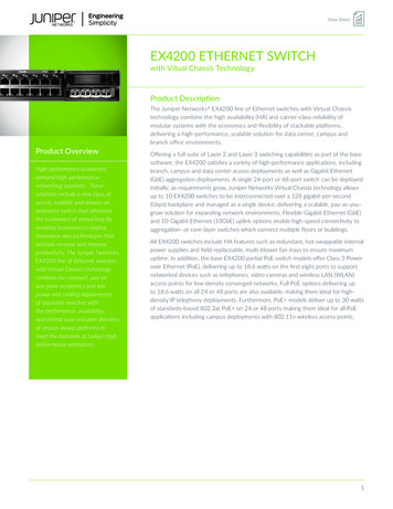
Tiffin Motorhomes, Inc.Powerglide Chassis Owner’s GuideLubrication PointsNO.1ComponentsRemarksTotalZF Independent FrontSuspension KnucklePostTwo grease fittings; Oneon top & bottom ofknuckle post, lubricateboth sides of suspension42Knuckle Pins3Height ControlLinkage PinsTwo grease pins perLinkage Front andRearSuspensionMain DriveshaftTwo grease fittings;lubricate both universaljoints.4568Two grease fittings; oneon top and one onbottom of knuckle pin.Lubricate both sides ofsuspension.Automatic SlackAdjustersOne grease fitting oneach slack adjuster. Oneadjuster on each side ofthe rear axle.Rear Brake CamshaftBracketOne grease fitting oneach bracket; Pump ingrease until it appears atthe slack adjuster end ofthe bracket. Lubricateboth sides of the rearaxle.Fan DriveshaftOne grease fitting on slipjoint.18483221
Tiffin Motorhomes, Inc.Powerglide Chassis Owner’s GuideMaintenance PartsPrimary Fuel Filter / Water Sep W/ WIF sensorFleetguard part #FS1003Tiffin part # 31647Secondary Fuel FilterFleetguard part #FF5636Engine Oil FilterFleetguard part #LF9009Engine Air FilterParker / Racor #094973007Tiffin part # 30596Alternator / AC BeltGates part #K080755Tiffin part # 5000139Fan Drive BeltCarlisle part #Tiffin part # 32306RSVX-750-219
Tiffin Motorhomes, Inc.Powerglide Chassis Owner’s GuideFor assistance with yourTiffin PowerGlide Chassis Please contact one of the followingChassis Specialists at Tiffin Motorhomes, Inc.256-356-8661Plant ManagerGary Harris, extension 2288PartsBobby Luther, extension 2382Mechanical EngineerBrad Warner, extension 2267Electrical EngineerDennis Baldwin, extension 2363Please have your Chassis VIN # readywhen you call20
Tiffin Motorhomes, Inc.Powerglide Chassis Owner’s GuidePre-Trip Inspection Check fluid levels & add as necessary Check tire inflation pressure Look for fluid leaksBefore starting your motor home daily, a few things must be checked. By doing so, youensure that a safe trip is in order and lessen your chances of experiencing difficulties whileon the road. Check the tires for proper inflation pressure and any damage. Also check the inner duals.Refer to the air pressure charts in this manual for proper inflation pressures. Look for fluid leaks under the motor home. This can prevent any serious problems fromoccurring later. Check the coolant level in the reservoir and add a 50/50 mix of coolant and water ifnecessary. This reservoir can be found on the rear of your vehicle. Check SCA (supplemental coolant additive) and freeze point every 6 months or25,000 miles. Recharge as required.CAUTION: IF THE WATER TEMP IN YOUR ENGINE IS GREATER THAN 120DEGREES, DO NOT REMOVE THE RADIATOR CAP! YOU COULD BESEVERELY BURNED! Approximate COOLING SYSTEM CAPACITIES—does not include the heater core orother auxiliary systems added by coach manufacturer: Cummins ISL - Side Radiator 56 Qt. or 14 Gallons. Check transmission fluid level Check engine oil level Check for small animals in engine compartment like squirrels, and cats Check the power steering fluid reservoir21
Tiffin Motorhomes, Inc.Powerglide Chassis Owner’s GuidePre-Trip InspectionCheck fuel/water separatorISC / ISL Check fuel/water separator and drain any water or contamination that may be present.After you have completed your inspection, you may now start your engine. Turn the key to therun position and wait for the wait to start light (in some cases it may read ―Inlet heater‖) to turnoff. You may now start the engine. Never use ether or any other starting fluids to start theelectronic engine. The inlet heater can ignite the fumes and cause an explosion in the airinlet system. Once you have started the engine, monitor your gauges carefully. Make sure thatthe oil pressure rises within 15 seconds. If it does not, shut down the engine and call a repairfacility to determine the cause.22
Tiffin Motorhomes, Inc.Powerglide Chassis Owner’s GuidePre-Trip InspectionFilter Restriction Indicator Check air filter restriction indicatorBrand New Air Cleaner10‖ to 12‖ of Vacuum Engine Air Cleaner Element should be changed when the air inlet restriction indicator reaches25 inches of vacuum or every two years whichever occurs first.23
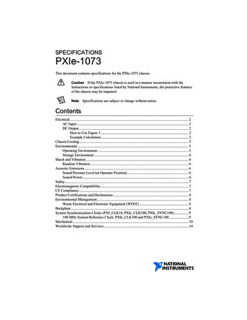
Tiffin Motorhomes, Inc.Powerglide Chassis Owner’s GuideInstruments & ControlsWARNING LAMPMODULEMASTER GAUGESPEEDOMETERMESSAGECENTER3-IN-1 GAUGE4-IN-1 GAUGEGauge and Warning Lamp Layout24
Tiffin Motorhomes, Inc.Powerglide Chassis Owner’s GuideInstruments & Controls14142352531.2.3.4.5.TachometerLow Fuel Warning LampFuel GaugeLow Battery Warning LampVoltmeter1.2.3.4.5.6.6Oil Pressure GaugeOil Pressure Low Warning LampFront (Secondary) Air Press. GaugeCoolant Temperature GaugeHigh Temperature Warning LightRear (Primary) Air Press. Gauge12431.2.3.4.SpeedometerMessage CenterMessage Center ―m‖ ControlMessage Center ―t‖ Control25
Tiffin Motorhomes, Inc.Powerglide Chassis Owner’s GuideInstruments & Controls123456131491015111612Warning Lamp Module1.2.3.4.5.6.7.8.9.10.11.12.13.14.15.16.Left Turn IndicatorJacks Down WarningCruise Switch StatusHeadlamp High Beam IndicatorCheck Transmission WarningSeat Belt WarningCheck Message CenterRight Turn IndicatorCheck ABS Warning LightDiesel Particulate Filter Indicator LampStop Engine Warning LampCheck Engine Warning LampPark Brake IndicatorLow Air Warning IndicatorHigh Exhaust Temp Warning LampWait To Start Lamp2678
Tiffin Motorhomes, Inc.Powerglide Chassis Owner’s GuideInstruments & ControlsMessage CenterDuring normal operation the LCD displays the odometer value on the top line and a selectedparameter on the second line.DRIVE MODE - Display First LineFirst line display parameters are odometer and measurement unit selection. Speedometer can be setto read MPH or km/h by changing this selection. See section on settings and diagnostics.Speedometer Setup - UnitsSpeedometer can be set to read MPH or km/h by changing this selection. See section on settings anddiagnostics.FIRST LINESECOND LINE1234.5 miMPH1234.5 km20.3 miTRIP20.3 kmkm/hTRIPOdometerThe odometer function is always shown with key ON. It can be displayed on the LCD in miles orkilometers. The odometer reading can be displayed when the ignition switch is OFF by activatingthe gauge backlight.DRIVE MODE - Display Second lineSecond line display parameters are selected by pressing the m button for less than 5 seconds.Pressing the m or t buttons displays a different parameter from the list.The selected parameter is highlighted with reverse video (sample). The selected parameter isretained automatically after 5 seconds of inactivity; no further button presses are required. When theparameter is retained, the reverse video disappears.27
Tiffin Motorhomes, Inc.Powerglide Chassis Owner’s GuideInstruments & ControlsTrip Odometer* Metric version reads in km1234.5 mi20.3 miMPHTRIPInstantaneous Fuel Economy*Metric version reads in L/100km1234.5 miMPH20.3 mpg Inst FAverage Fuel Economy* Metric version reads in L/100km1234.5 miMPH20.3 mpg Avg FHourmeter1234.5 miMPH67.8 hr28
Tiffin Motorhomes, Inc.Powerglide Chassis Owner’s GuideInstruments & ControlsIdle Speed AdjustmentWhen vehicle speed is 0, the cruise on/off switch is in the off position and the cruise control Set orResume switch is pressed, the Idle Speed Adjust screen will display on the message center.IDLE SPEED775 RPMm for t for -Idle speed is adjusted by using the Set & Resume or by using the message center control switches.The actual engine speed will be displayed as the adjustment is made. Once the Set or Resumeswitch has been released, there will be a 10 second delay in removing the Idle Speed Adjust screenfrom the LCD. The new idle speed will be retained in the engine control module as the default setting.Settings and Diagnostic ScreensThe Settings and Diagnostic screens can only be accessed when the vehicle speed is equal to 0 mphand the display is in its normal operating (Drive Mode) screen. Pressing and holding the m button forlonger than 5 seconds enables the Settings and Diagnostics menu.Once in the Settings and Diagnostics menu, pressing the m or t buttons separately moves thereverse video highlight (example) up or down through the list, as indicated by the arrows. Thehighlighted item is selected when both m and t buttons are pressed at the same time. If no button ispressed for 5 seconds, the LCD will go back to the standard Drive Screen. The items available in themenu are:1-English/Metric Units2-Contrast Adjust3-Instrument Diagnostics\/ Select/\4-Engine Diagnostics5-Transmission Diagnostic6-ABS Diagnostics\/ Select7-Read Parameters/\\/ SelectSet UnitsEnables the screen used to select if values are to be displayed in English or Metric unitsCurrent UnitsENGLISHPress t for METRICPress m to exitCurrent UnitsMETRICPress t for ENGLISHPress m to exit29/\
Tiffin Motorhomes, Inc.Powerglide Chassis Owner’s GuideInstruments & ControlsContrastEnables the screen used to set the LCD contrast. Pressing the m ( ) button will increase contrastwhile pressing the t (-) button will decrease contrast. After 5 seconds of inactivity, the screen revertsback to the Drive Mode screen. The new contrast setting is written to memory upon returning to theDrive Mode screen.CONTRAST Instrument DiagnosticsEnables the screens used to perform diagnostic testing of the instrument system. Navigation throughthese menus is the same format as the main menu.1-Gauge Test2-Lamp Test3-LCD Test\/ Select4-Input Status/\\/ Select/\Gauge TestEach gauge pointer will be driven through three positions, pausing at each position for ½ second. TheLCD shows the position of the pointer as a percentage of full scale. At the end of the test, the gaugesrevert back to their original pointer position and the program returns to the Instrument Diagnosticsmenu. When available, the warning light internal to the gauge will illuminate steady for the gaugebeing tested. Pressing the m button (Exit) will end the test and return to the Instrument Diagnosticsmenu. Sample LCD screens:Fuel LevelEXIT0%Fuel LevelEXIT3050%Fuel LevelEXIT100%
Tiffin Motorhomes, Inc.Powerglide Chassis Owner’s GuideInstruments & ControlsLamp TestEach warning bank light in the instrument panel that is controlled by the gauge network will be tested.This test does not test the actual light on the vehicle (vehicle load). Warning lights in the secondarygauges are not tested with this feature. They are tested during the Gauge Test diagnostic. At the startof the test, all warning bank lights are turned off. Each light is then toggled to the “on” state, and then“off”. The LCD displays the name of the light being tested and its status. At the end of the test, thelights revert back to their original state (on or off) and the program returns to the InstrumentDiagnostics menu. Pressing the m button (Exit) will end the test and return to the menu. Sample LCDscreens:High BeamEXITHigh BeamONEXITOFFLCD TestDisplays the ACTIA logo in normal and reverse video three times and then returns to the InstrumentDiagnostics menu.InputsThe module, pin number, and status of each input defined in the system are displayed for this test.Pressing the m button exits the test and returns to the menu. Pressing the t button scrolls the displayto the next 4 inputs. For binary inpu
Tiffin Motorhomes, Inc. Powerglide Chassis Owner's Guide 6 Allison Transmission Fluid Level Check Be sure transmission is at operating temperature (140 to 220 F) Vehicle is parked on level ground Transmission in neutral and engine at idle Wait until vehicle has been stationary for two minutes Simultaneously press the up and down arrow keys