Transcription
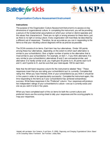
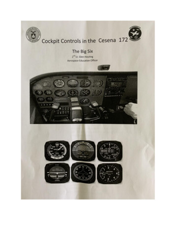
Cessna 172 Instrument PanelAviation Six Pack – Instrument 6 PackBefore the days of Glass Panels, this was a typical General Aviation Instrument Panel.Even with the trend towards only Glass Cockpits, the basic Flight Instruments remain the same.Six Pack?The Six Pack is not a half-dozen beers, and it’s not a well toned and muscled belly. Instead,Pilots know the 6-Pak refers to the six Primary Flight Instruments.3 3 6The 6 basic flight instruments are divided into two categories. Three instruments are connectedto the aircraft’s Pitot Static Pressure System, and the other three are Gyro Instruments typicallydriven by the aircraft’s Vacuum system pump. It’s important for student pilots to recognize thisdifference. In the event of a partial system failure, the pilot will be better prepared when theyrecognize the specific instruments that may be affected.The SIX PACK:1.2.3.4.5.6.Airspeed Indicator (Pitot Static)Attitude Indicator (Gyro)Altimeter (Pitot Static)Vertical Speed Indicator (Pitot Static)Heading Indicator (Gyro)Turn Coordinator (Gyro)These six instruments are denoted by number on the Cessna 172 Instrument Panel above.Every pilot must have a thorough understanding of these six flight instruments – the Aviation SixPack – and the way they work. Pilots should have knowledge of each instrument’s characteristicsand limitations. During flight, a pilot must interpret the information displayed on these six flightinstruments to fly safely and within the limitations of the aircraft’s safe operating envelope.
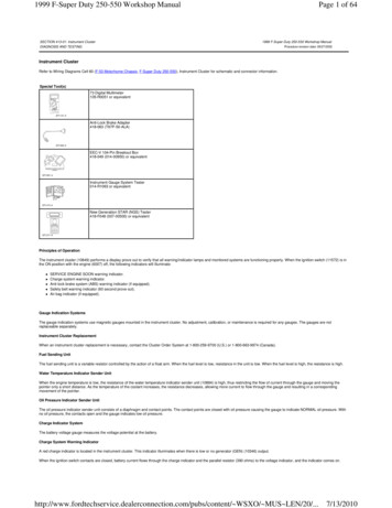
Let’s take a closer look at each of these six flight instruments and how they work.Six Pack – 6 Pack – Cockpit InstrumentsPitot Static InstrumentsThe Pitot Static System relies on a Pitot Tube to measure the dynamic pressure due to theforward motion of the airplane through the air, and Static Vents to measure the static, outsidebarometric pressure as the airplane gains or loses altitude. The three flight instruments connectedto the Pitot Static System include the Airspeed Indicator, Altimeter, and Vertical SpeedIndicator.Gyroscopic InstrumentsA Gyroscope is a rotor or spinning wheel, rotating at a high speed. Usually, this is powered bythe Vacuum System Pump. Gyroscopic Inertia is the tendency of a rotating body to maintain itsplane of rotation, known as Rigidity in Space. Gyroscopic Precession is the tendency of arotating body to consistently react to a force being applied by turning in the direction of itsrotation exactly 90 degrees to its axis. These principles of physics are used to make very preciseFlight Instruments including the Attitude Indicator, Heading Indicator, and Turn Coordinator.#1) Airspeed IndicatorThe Airspeed Indicator measures the speed of the aircraft through the air, but really this is thespeed at which the air is flowing over the airplane. And remember, this is not a measurement ofground speed. The dial is usually calibrated in Nautical miles known as KNOTS.KNOTS vs. MilesKNOTS are a measure of speed based on nautical, or sea miles. Aviation uses both nautical andstatute miles for measuring distance and speed, but the Airspeed Indicator typically showsKNOTS.
Nautical Mile 6,076 feetStatute Mile 5,280 feetTherefore, 1 Nautical Mile distance 1.15 Statute Mile distanceThe airspeed indicator is connected to the Pitot Static System. To give a reading of speedthrough the air, the flight instrument measures the difference between the dynamic pressure inthe Pitot Tube and the atmospheric pressure from the Static vent. When the airplane is standingstill on the ground, the pressure in the two systems will be the same resulting in a reading ofzero. However, when the airplane is travelling through the air, the dynamic pressure in the Pitotsystem will increase and a reading is registered.Indicated AirspeedThe Indicated airspeed (IAS) is the reading displayed on the face of the instrument. The smallwindows at the top and bottom of the Airspeed Indicator are used for determining True Airspeed(TAS). Remember, the Airspeed Indicator displays the Indicated Air Speed (IAS), andadjustments are needed to calculate the Calibrated Airspeed (CAS) and True Airspeed (TAS).Speed Ranges and limitations are marked on the Airspeed Indicator and are specific to the makeand model of the aircraft. Different makes and models of airplanes will have the markings atdifferent speeds based on limitations of each aircraft. Typically Green markings on instrumentsreflect normal operations, and Red markings reflect abnormal operations or limitations.The Red LineThe speed marked by the Red Line is the Never Exceed Speed (Vne). This speed should never beexceeded in the Aircraft or structural damage may occur.The Yellow ArcThe speed range marked by the Yellow Arc is the Caution Speed Range. Speed range indicatedby the Yellow Arc is for Smooth Air Only.The Green ArcThe Green Arc denotes the Normal Operating Airspeed Range.The White ArcThe Flaps Operating Range is denoted by the White Arc. Flaps may only be used within thisrange of speeds.
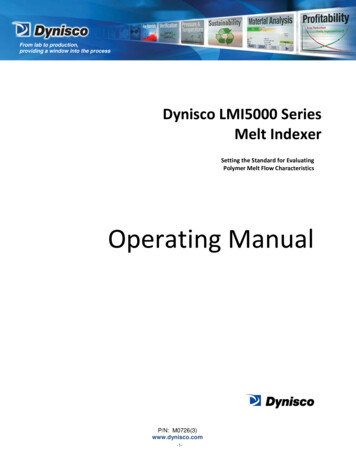
#2) Attitude IndicatorThe Attitude Indicator is also called the artificial horizon or the gyro horizon. This flightinstrument depicts the position of the airplane in relation to the horizon. It shows whether thewings are level, and if the plane is climbing or descending, or flying straight and level. A pair ofwings represents the attitude of the aircraft. Behind the aircraft is a ball. The top is blue,representing the sky, and the bottom half is usually brown, representing the ground. As theairplane manoeuvres in the air, the pair of wings will show the degree of bank and pitch attitude.The Attitude Indicator is a Gyroscopic Instrument, and it uses a Gyroscope to stabilize a horizonbar which stays parallel to the natural horizon. The miniature airplane in the centre of theAttitude Indicator will pitch and bank around the horizon bar to indicate the airplanes currentattitude relative to the horizon.#3) AltimeterThe Altimeter measures the Altitude or height of the aircraft above Sea Level. Remember,ground elevation varies widely, so the Altimeter reading does not measure height about theGround, but instead above Sea Level. The Pilot must be aware of the Ground elevation, to thencalculate the height of the airplane above the Ground.
Similar to a clock, an Altimeter has three hands. The fastest moving hand reads in Hundreds ofFeet. The shortest hand reads in Thousands of feet. The Longest hand, which moves the slowest,reads in Tens of Thousands of feet. (On some altimeters, the Tens of Thousands of feet isrepresented with the shortest hand, instead of the Longest Hand)The Altimeter pictured here has a reading of 1,410 feet above sea level. The fastest moving hand(Hundreds) is between the 4 and 5, and the small hash marks represent 20 feet each. Therefore,this hand has a reading of 410 feet. The shortest hand (Thousands) is between the 1 and 2.Therefore, the current altitude would be 1,410.The Altimeter reading is based on barometric pressure, and barometric pressure is constantlychanging. This requires the altimeter to be set prior to every flight, and during flight asbarometric pressure in your flying area changes.#4) Vertical Speed Indicator (VSI)The Rate of Climb and Rate of Descent are indicated on the Vertical Speed Indicator (VSI). Thisis measured in Feet Per Minute, and displayed in Hundreds of FPM.The VSI flight instrument measures the vertical speed (vertical velocity, or rate of climb). Thisinstrument is connected to the static air pressure system. There is a standard barometric pressurechange with altitude changes, and this standard rate of change is calibrated to measure theaircraft’s change in altitude and rate of change.The pilot relies on both the Altimeter and the Vertical Speed Indicator to monitor altitude andaltitude changes. At a glance, the VSI shows the pilot if they are flying at a steady altitude, or ifthey are ascending or descending, and the rate at which their altitude is changing in feet perminute.
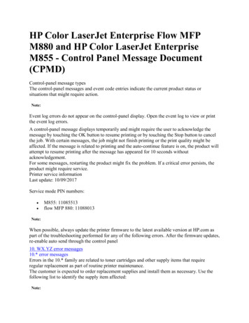
#5) Heading IndicatorThe Heading Indicator is another Gyroscopic flight instrument. Sometimes known as theDirectional Gyro or Heading Gyro, this instrument is the principal direction instrument used inflight.The Heading Indicator is gyroscopically stabilized. Unlike the magnetic compass, the DirectionalGyro is not as affected by banks, turns, and speed changes. However, the Heading Indicator isNOT a magnetic compass.The Heading Indicator must be set according to the Magnetic Compass indication before takeoff,and occasionally adjusted to the Magnetic compass while the aircraft is in steady, level flight.Precession error must be corrected for at regular intervals of about 15 minutes by re-calibratingthe Heading Indicator (HI) to the Magnetic Compass.The outline of an aircraft is positioned over a 360 degree scale with markings for North, East,South and West. The larger markings indicate 10 degrees each, and the smaller markings denote5 degree variations.#6) Turn Coordinator
This is another Gyroscopic instrument. This instrument gives information about the direction andrate of a turn. Additionally, it indicates if the turn is being flown in coordinated flight. If theaircraft is slipping or skidding during a turn, the ball (or inclinometer) in the bottom portion ofthe Turn Coordinator will not be centred. During a coordinated turn, the ball will remaincentered. If the ball is not centered, the pilot must adjust the turn by using more or less rudder tocorrect for adverse yaw.Standard Rate TurnThe white lines indicate the bank amount for a Standard Rate Turn. The turn indicator indicatesthe rate of turn, and not the amount of turn. A Standard Rate Turn, or Rate One Turn, will give astandard rate of turn of 3 degrees per second. Therefore, a 360 degree turn will be exactly 2minutes. This allows the pilot to determine by time, the degrees of turn. For instance, a pilotcould use a standard rate of turn for 60 seconds, and confidently know they have changed theircourse by 180 degrees based on 3 degrees per second. This becomes particularly important whenpilots begin Instrument flying.Six Pack – Primary Flight Instruments – Cockpit Instrument PanelEvery Pilot needs to have a complete and proper understanding of the Six Pack – The PrimaryFlight Instruments.
Cessna 172 Instrument Panel Aviation Six Pack – Instrument 6 Pack Before the days of Glass Panels, this was a typical General Aviation Instrument Panel. Even with the trend towards only Glas