Transcription
—ABB measurement & analy tics data sheetModel 266HSHGauge pressure transmitter low powerconsumption (1 to 5 V DC and HART)
—Measurement made easyEngineered solutions for all applications2266H S H gauge p ress ur e tr ansmit te rs DS/266HSH/LowP-EN Re v. D—Base accuracy 0.15 % of calibrated span—Reliable sensing system coupled with very latest digitaltechnologies provides large turn down ratio up to 100:1—Version for low consumption 1 to 5 V DC output with 3 mA maximum consumption—Product in compliance with Directive 2011/65/UE (RoHS II)
3266H SH g aug e p r ess ur e tr ansmit te rs D S/266H SH/LowP -EN Re v. D—Functional specifications—Operative limitsPressure limits:Overpressure limitsWithout damage to the transmitterRange and span limitsSensor codePQSWUpper rangelimit (URL)Lower range limit(LRL) - NOTE266HSHMinimum span266HSH2400 kPa-100 kPa24 kPa24 bar-1 bar0.24 bar348 psi-14.5 psi3.5 psi8000 kPa-100 kPa80 kPa80 bar-1 bar0.8 bar1160 psi-14.5 psi11.6 psi16000 kPa-100 kPa160 kPa160 bar-1 bar1.6 bar2320 psi-14.5 psi23.2 psi70000 kPa-100 kPa7000 kPa700 bar-1 bar70 bar10150 psi-14.5 psi1015 psiSensor codeFill fluidOverpressure limitsP to SSilicone oil0.07 kPa abs, 0.7 mbar abs, 0.5 mmHgand 21 MPa, 210 bar, 3045 psiWSilicone oil0.07 kPa abs, 0.7 mbar abs, 0.5 mmHgand 105 MPa, 1050 bar, 15225 psiProof pressureThe transmitter can be exposed without leaking to linepressure of up to the following values:Sensor codeProof pressureP to S40.25 MPa, 402.5 bar, 5836 psiW171.5 MPa, 1715 bar, 24868 psiMeet ANSI/ISA–S 82.03 hydrostatic test requirements.NOTE: with atmospheric pressure reference of 1 bar (14.5 psi)Temperature limits C ( F):Span limitsMaximum span URLIT IS RECOMMENDED TO SELECT THE TRANSMITTERSENSOR CODE PROVIDING THE TURNDOWN VALUE ASLOWEST AS POSSIBLE TO OPTIMIZE PERFORMANCECHARACTERISTICS.Zero suppression and elevation The zero position and span can be set to any value withinthe measuring range limits listed in the table if: Set span minimum spanDampingConfigurable time constant between 0 and 60 s.This is in addition to the sensor response time.Ambientis the operating temperatureModels 266HSHAmbient temperature limitsSilicone oil for sensor P to W–40 and 85 C (–40 and 185 F)IMPORTANTFor Hazardous Atmosphere applications see thetemperature range specified on the certificate/approvalrelevant to the aimed type of protection.Models 266HSHAmbient temperature limitsLCD integral display–40 and 85 C (–40 and 185 F)LCD display may not be clearly readable below –20 C (–4 F) or above 70 C ( 158 F)Warm-up timeReady for operation as per specifications in less than 10 swith minimum damping.ProcessModels 266HSHProcess temperature limitsInsulation resistance 100 MΩ at 500 V DC (between terminals and ground).Silicone oil for sensor P to W–40 and 121 C (–40 and 250 F)(1)(1) 100 C (212 F) for application below atmospheric pressureStorageModels 266HSHAmbient temperature limitsStorage limits–50 and 85 C (–58 and 185 F)LCD integral display–40 and 85 C (–40 and 185 F)
266H S H gauge p ress ur e tr ansmit te rs DS/266HSH/LowP-EN Re v. D4—Environmental limitsElectromagnetic compatibility (EMC)Comply with EN 61326-1.Surge immunity level (with surge protector): 4 kV(according to IEC 1000-4–5 EN 61000–4–5)Pressure Equipment Directive (PED)Comply with 2014/68/UE to standard ANSI/ISA61010-1:2012 Category III Module H for PS than 20 MPa, 200 bar Sound Engineering Practice (SEP) for PS 20 MPa,200 barHumidityRelative humidity: Up to 100 %.Condensing, icing: admissible.Vibration resistanceAcceleration up to 2 g at frequencies of up to 1000 Hz(according to IEC 60068-2-6).Acceleration limited to 1 g for housing out of stainlesssteel.Shock resistanceAcceleration: 50 gDuration: 11 ms(according to IEC 60068-2-27).Wet and dust-laden atmospheresThe transmitter is dust and sand tight and protectedagainst immersion effects as defined by EN 60529 (1989)to IP 67 (IP 68 on request) or by NEMA Type 4X.Hazardous atmospheresWith or without integral LCD displayFM Approvals US and FM Approvals Canada (code EB): Explosionproof (US): Class I, Div. 1, Groups A, B, C, DExplosionproof (Canada): Class I, Div. 1, Groups B, C, DDust ignitionproof : Class II, Div. 1, Groups E, F, GSuitable for: Class II, Div. 2, Groups F, G; Class III, Div.1, 2REFER TO CERTIFICATES FOR AMBIENT TEMPERATURERANGES (WITHIN THE LIMITS OF -50 TO 85 C) RELATEDTO THE DIFFERENT TEMPERATURE CLASSES.SENSOR CODE "W" IS NOT IN COMPLIANCE WITHISA 12.27.01 FOR SEALING REQUIREMENTS.—Electrical data and optionsOptional indicatorsIntegrated digital display (code LS)Wide screen LCD, 128 x 64 pixel,52.5 x 27.2 mm (2.06 x 1.07 in.) dot matrix.User selectable application-specificvisualizations.Display may also indicate static pressure,sensor temperature and diagnosticmessages.Optional surge protectionUp to 4kV voltage 1.2 μs rise time / 50 μs delay time to half value current 8 μs rise time / 20 μs delay time to half valueLow power consumption 1 to 5 V DC outputwith HART Power supplyThe transmitter operates from 8 to 30 V DC with no loadand is protected against reverse polarity connection.Current draw 3 mARippleless than 2 %Output load 100 kΩOutput signalTwo–wire 1 to 5 V DC, user-selectable for linear or 22points linearization table (i.e. for horizontal or sphericaltank level measurement).HART 7 communication provides digital process variablesuperimposed on voltage signal, with protocol based onBell 202 FSK standard.A minimum of 250 Ω is required for HART communication.Output rangeOverload condition Lower limit: 0.97 V DC Upper limit: 5.2 V DCAlarm voltage Low limit: 0.95 V DC High limit: 5.4 V DCFactory setting: high alarm voltage
5266H SH g aug e p r ess ur e tr ansmit te rs D S/266H SH/LowP -EN Re v. D—Specification - measuring accuracyStated at reference condition to IEC 60770 ambienttemperature of 20 C (68 F), relative humidity of 65 %,atmospheric pressure of 1013 hPa (1013 mbar), mountingposition with vertical diaphragm and zero based range fortransmitter with isolating diaphragms in AISI 316 L ss orHastelloy and silicone oil fill and HART digital trim valuesequal to 1 V and to 5 V span end points, in linear mode.Unless otherwise specified, errors are quoted as % ofspan.Some performance referring to the Upper Range Limit areaffected by the actual turndown (TD) as ratio betweenUpper Range Limit (URL) and calibrated span.IT IS RECOMMENDED TO SELECT THE TRANSMITTERSENSOR CODE PROVIDING THE TURNDOWN VALUE ASLOWEST AS POSSIBLE TO OPTIMIZE PERFORMANCECHARACTERISTICS.Dynamic performance (according to IEC 61298–1 definition)Sensor codeTime constant(63.2 % of total step change)P to S 70 msW 150 msDead time for all sensors30 msResponse time (total) dead time time constantModelSensorFor TD rangeMeasuring error266HSHP to SP to SWWFrom 1:1 to 10:1From 10:1 to 100:1From 1:1 to 5:1From 5:1 to 10:1 0.15 % (0.015 x TD) % 0.15 % (0.03 x TD) %Ambient temperatureper 20K change between the limits of –40 C to 85 C(per 36 F change between the limits of –40 to 185 F):ModelSensorFor TD up toMeasuring error266HSHP and QS and W10:110:1 (0.06 % URL 0.09 % span) (0.08 % URL 0.13 % span)Supply voltageWithin voltage/load specified limits the total effect is lessthan 0.005 % of URL per volt.LoadWithin load/voltage specified limits the total effect isnegligible.Electromagnetic fieldMeets all the requirements of EN 61326 for surgeimmunity level.Common mode interferenceNo effect from 100Vrms @ 50Hz, or 50 V DCMounting positionNo effect for rotation on diaphragm plane. A tilt up to 90 from vertical causes a zero shifts up to 0.5 kPa, 5 mbar or2 inH2O, which can be corrected with zero adjustment.No span effect.Stability 0.15 % of URL over a ten years period for sensors P to W.
266H S H gauge p ress ur e tr ansmit te rs DS/266HSH/LowP-EN Re v. D6—Specification – physical(Refer to ordering information sheets for variantavailability related to specific model or versions code)MaterialsProcess isolating diaphragms (*)AISI 316 L ss; Hastelloy C-276 .Process connection (*)AISI 316 L ss; Hastelloy C-276 .Sensor fill fluidSilicone oil.Mounting bracket (**)Zinc plated carbon steel with chrome passivation; AISI 316 Lss.Sensor housingAISI 316 L ss.Electronic housing and coversAluminium alloy (copper content 0.3 %) with baked epoxyfinish (colour RAL9002); AISI 316 L ss.CalibrationStandard: at maximum span, zero based range, ambienttemperature and pressure;Optional: at specified range and ambient conditions.Optional extrasMounting brackets (code Bx)For 60mm. (2in) pipes or wall mounting.Display (code L9)4-position (at 90 ) user orientable.Optional plates (code Ix)Code I2: plate for tag (up to 31 characters) and calibrationdetails (up to 31 characters: lower and upper range valuesand engineering unit) fixed onto transmitter housing.Code I1: AISI 316 ss wired-on plate with laser printedcustomized data (4 lines of 32 characters with 4 mm/0.16 in. height).Surge protection (code S2)Covers O-ringBuna N.Local adjustments (zero and span) Internal for zero and span (on communication board).PlatesTransmitter nameplate: AISI 316 ss screwed to theelectronics housing.Certification plate and optional tag/calibration plate :selfadhesive attached to the electronics housing orAISI 316 ss fastened to the electronics housing with rivetsor screws.Optional wired-on customer data plate: AISI 316 ss.Laser printing on metal or thermal printing on selfadhesive.Test Certificates (test, calibration, material traceability)(codes Cx and Hx)Tag and manual language (codes Tx and Mx)Manifold mounting (code A1)Factory mounting and pressure test of ABB M26manifolds.(*) Wetted parts of the transmitter.(**) U-bolt material: high-strength alloy steel or AISI 316 L ss;bolts/nuts material: high-strength alloy steel or AISI 316 ss.
266H S H gauge p ress ur e tr ansmit te rs DS/266HSH/LowP-EN Re v. DProcess connections1/2 in.– 14 NPT male or femaleElectrical connectionsTwo 1/2 in. – 14 NPT threaded conduit entries, direct onhousingTerminal blockHART version: three terminals for signal/external meterwiring up to 2.5 mm2 (14 AWG), also connection points fortest and communication purposes.GroundingInternal and external 6 mm2 (10 AWG) ground terminationpoints are provided.Mounting positionTransmitter can be mounted in any position.Electronics housing may be rotated to any position. Apositive stop prevents over travel.Mass (without options)2.1 kg approx (4.6 lb). Add 650 g (1.5 lb) for packing.PackingCarton 27 x 24 x 20 cm approx (11 x 10 x 8 in.).7
266H S H gauge p ress ur e tr ansmit te rs DS/266HSH/LowP-EN Re v. D8—ConfigurationTransmitter with HART communicationStandard configurationTransmitters are factory calibrated to customer'sspecified range. Calibrated range and tag number arestamped on the tag plate. If a calibration range and tagdata are not specified, the transmitter will be suppliedwith the plate left blank and configured as follows:Engineering UnitkPa1 V DCZero5 V DC Upper Range Limit (URL)Output LinearDamping1sTransmitter failure mode UpscaleSoftware tag (8 characters max) BlankOptional LCD displayPV in kPa; output in V DCand in percentage onbargraphAny or all the above configurable parameters, includingLower range–value and Upper range-value which must bethe same unit of measure, can be easily changed using theHART hand–held communicator or by a PC running theconfiguration software with DTM for 266 models. Thetransmitter database is customized with specified flangetype and material, O–ring and drain/vent materials andmeter code option.Customer-specific configuration (option N6)The following data may be specified in addition to thestandard configuration parameters:Descriptor16 alphanumeric charactersMessage32 alphanumeric charactersDateDay, month, yearFor HART protocol available engineering units of pressuremeasure are :Pa, kPa, MPainH2O@4 C, mmH2O@4 C, psiinH2O@20 C, ftH2O@20 C, mmH2O@20 CinHg, mmHg, Torrg/cm2, kg/cm2, atmmbar, bar
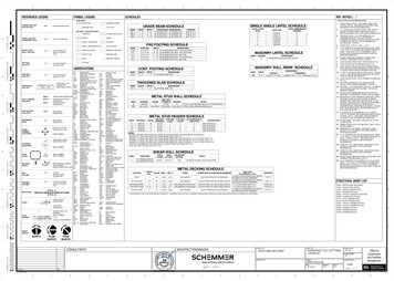
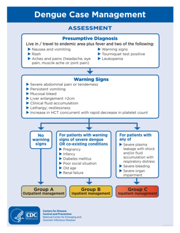
9266H SH g aug e p r ess ur e tr ansmit te rs D S/266H SH/LowP -EN Re v. D—Dimensions(not for construction unless certified) – dimensions in mm (in.)266HSH Transmitter with barrel housing - 1/2 NPT female connection for sensor P, Q and SAdjustments91 (3.58)Identificationplate18 (0.71)113 (4.45)18 (0.71)Space forIntegrated displaycover removal145 (5.71)Terminal side18 (0.71)16 (0.63)36 (1.42)Electronicside19 (0.75)Certificationplatehousing32 (1.26) width acrosssflats of exagon72 (2.83)108 (4.25)49 (1.93)266HSH Transmitter with barrel housing - 1/2 in. NPT female connection for sensor W91 (3.58)113 (4.45)18 (0.71)18 (0.71)16 (0.63)40 (1.58)72 (2.83)145 (5.71)18 (0.71)36 (1.42) width acrosss65 (2.56)72 (2.83)108 (4.25)flats of exagon
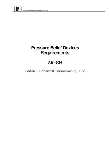
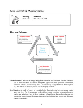
266H S H gauge p ress ur e tr ansmit te rs DS/266HSH/LowP-EN Re v. D10—.Dimensions(not for construction unless certified) – dimensions in mm (in.)266HSH Transmitter with barrel housing - 1/2 NPT male connection for sensor P, Q and S91 (3.58)113 (4.45)18 (0.71)18 (0.71)16 (0.63)39 (1.54)54 (2.13)145 (5.71)18 (0.71)32 (1.26) width acrosssflats of exagon72 (2.83)108 (4.25)49 (1.93)266HSH Transmitter with barrel housing - 1/2 NPT male connection for sensor W113 (4.45)18 (0.71)18 (0.71)18 (0.71)16 (0.63)52 (2.05)145 (5.71)91 (3.58)27 (1.06) width acrosssflats of exagon72 (2.83)108 (4.25)
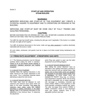
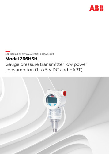
11266H SH g aug e p r ess ur e tr ansmit te rs D S/266H SH/LowP -EN Re v. D—Electrical connections1.5 V DC HART VersionInternal groundtermination point1 to 5 V DC out (Voltmeter)Power source -- Line loadExternal groundtermination pointHandheldcommunicatorHART handheld communicator may be connected at any wiring termination point in the loop, providing the minimumresistance is 250 ohm. If this is less than 250 ohm, additional resistance should be added to allow communications.
12266H S H gauge p ress ur e tr ansmit te rs DS/266HSH/LowP-EN Re v. D—Ordering informationBasic ordering information model 266HSH Gauge Pressure Transmitter low power consumption (1 to 5 V DC and HART)Select one character or set of characters from each category and specify complete catalog number.Refer to additional ordering information and specify one or more codes for each transmitter if additional options arerequired.Base model - 1st to 6th characters266HSHXXXXXGauge pressure transmitter, base accuracy 0.15 %Sensor Span Limits – 7th character24 and 2400 kPa0.24 and 24 bar3.5 and 348 psiP80 and 8000 kPa0.8 and 80 bar11.6 and 1160 psiQ160 and 16000 kPa1.6 and 160 bar23.2 and 2320 psiS7000 and 70000 kPa70 and 700 bar1015 and 10150 psiWDiaphragm material / Fill fluid (wetted parts) - 8th characterAISI 316L SST (1.4435)Silicone oilNACESHastelloy C-276Silicone oilNACEKProcess connection (wetted parts) - 9th characterAISI 316L ss1/2 in. - 14 NPT femaleNACEAISI 316L ss1/2 in. - 14 NPT maleNACEBHastelloy C-2761/2 in. - 14 NPT femaleNACE(Note 1)EHastelloy C-2761/2 in. - 14 NPT maleNACE(Note 1)KTHousing material and electrical connection - 10th characterAluminium alloy ( barrel version)1/2 in. - 14 NPTAAISI 316 L ss (barrel version) (I2 or I3 required) 1/2 in. - 14 NPTSOutput/Additional options - 11th characterLow power consumption 1 to 5 V DC and HART No additional optionsVLow power consumption 1 to 5 V DC and HART Options requested by “Additional ordering code”4
13266H SH g aug e p r ess ur e tr ansmit te rs D S/266H SH/LowP -EN Re v. DAdditional ordering information model 266HSH Gauge Pressure Transmitter low power consumption (1 to 5 V DC and HART)Add one or more 2-digit code(s) after the basic ordering information to select all required optionsXXXXXXXXXXXXDrain/vent valve (material and position) (wetted parts)AISI 316 L ssNACE(Notes 2, 4)VAHastelloy C-276 NACE(Notes 3, 4)VBHazardous area certificationsFm Approvals (usA and canada) explosion Proof(SENSOR CODE "W" NOT IN COMPLIANCE WITH ISA 12.27.01 FOR SEALING REQUIREMENTS)EBIntegral LCDIntegrated digital LCD displayLSMounting bracket (shape and material)For pipe/wall mounting - Carbon steelFor pipe/wall mounting - AISI 316 L ss(Not suitable for AISI housing)B6B7SurgeSurge/Transient ProtectorS2Operating manual (multiple selection allowed)SpanishM3FrenchM4EnglishM5
266H S H gauge p ress ur e tr ansmit te rs DS/266HSH/LowP-EN Re v. D14— Ordering information.Additional ordering information model 266HSH Gauge Pressure Transmitter low power consumption (1 to 5 V DC and HART)Add one or more 2-digit code(s) after the basic ordering information to select all required optionsXXXXXXXXXXXXPlates languageSpanishT3FrenchT4Additional tag plateSupplemental wired-on stainless steel plateI1Tag and certification stainless steel plates and laser printing of tagI2Tag, certification and supplemental wired-on stainless steel plates and laser printing of tagI3ConfigurationStandard – Pressure inH2O/psi at 68 F; Temperature deg. FN2Standard – Pressure inH2O/psi at 39.2 F; Temperature deg. FN3Standard – Pressure inH2O/psi at 20 C; Temperature deg. CN4Standard – Pressure inH2O/psi at 4 C; Temperature deg. CN5CustomN6Certificates (up to 2 different selections allowed)Inspection certificate EN 10204–3.1 of calibration (9-point)C1Inspection certificate EN 10204–3.1 of the pressure testC5PMI test of wetted partsCTMaterial traceabilityCertificate of compliance with the order EN 10204–2.1 of process wetted partsH1Inspection certificate EN 10204–3.1 of process wetted partsH3Test report EN 10204–2.2 of pressure bearing and process wetted partsH4AccessoryManifold mounting and pressure test (10000 psi aphragm code SProcess connection code E, KProcess connection code B, Tsensor code WStandard delivery items (can be differently specified by additional ordering code) No drain/vent valves General purpose (no electrical certification) No display, no mounting bracket, no surge protection Multilanguage short-form operating instruction manual and labels in english (metal nameplate; self-adhesive certificationand tag) Configuration with kPa and deg. C units No test, inspection or material traceability certificatesTrademarks Hastelloy C-276 is a Cabot Corporation trademark
266H S H gauge p ress ur e tr ansmit te rs DS/266HSH/LowP-EN Re v. D15
—ABB Ltd.Measurement & AnalyticsHoward Road St. NeotsCambridgeshire PE19 8EUUKTel: 44 (0)1480 475321Fax: 44 (0)1480 217948ABB S.p.A.Measurement & AnalyticsVia Luigi Vaccani 422016 Tremezzina Loc. Ossuccio (CO)ItalyTel: 39 0344 58111ABB Inc.Measurement & Analytics125 E. County Line RoadWarminster PA 18974USATel: 1 215 674 6000Fax: 1 215 674 7183We reserve the right to make technical changes or modify the contents of this document withoutprior notice. With regard to purchase orders, the agreed particulars shall prevail.ABB does not accept any responsibility whatsoever for potential errors or possible lackof information in this document.We reserve all rights in this document and in the subject matter and illustrations contained therein.Any reproduction, disclosure to third parties or utilization of its contents – in wholeor in parts – is forbidden without prior written consent of ABB. Copyright 2018 ABBAll rights reserved3KXP226600R1001D S /2 66 H SH / LowP -E N Rev. D 02.2019abb.com/measurement
Operative limits Pressure limits: Overpressure limits Without damage to the transmitter Sensor code Fill fluid Overpressure limits P to s silicone oil 0.07 kPa abs, 0.7 mbar abs, 0.5 mmHg and 21 MPa, 210 bar, 3045 psi W silicone oil 0.07 kPa abs, 0.7 mbar abs, 0.5 mmHg and 105 MPa, 1050 bar, 15225 psi Proof pressure