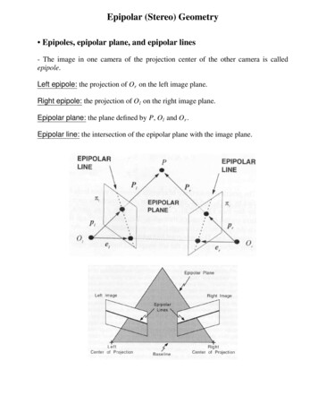
Transcription
ISSN 2319 – 1953International Journal of Scientific Research in Computer Science Applications and Management StudiesReview of Multimodality Medical Image FusionUsing Combined Transform Techniques for ClinicalApplicationB.Rajalingam1, Dr. R.Priya2*1Research Scholar, 2Associate ProfessorDepartment of Computer Science & Engineering, Annamalai University,Chidambaram, Tamilnadu, Indiarajalingam35@gmail.com1, prykndn@yahoo.com2Abstract – In recent research area multimodality medical imagefusion technique is one of the important researches in the field ofmedical imaging and radiation medicine. Currently, manyresearchers have paid their more attention to multimodalmedical image fusion technique based on various transformtechniques. In categorize to make the researchers to rapidlyrecognize the research improvement of multimodality medicalimage fusion based on combined transform techniques, it issystematically reviewed in this paper. On the basis of qualitativeand quantitative analysis performance metrics are discussed inthis paper. Finally review the applications of available combinedtransform techniques using in the field of medical image fusion.Subsequently, some existing problems are summarized, while wegive some suggestions for the future research.Keywords: CT, MRI, PET, SPECT, Multimodal medical image,DWT, DCT and Curvelet Transform1 INTRODUCTIONMedical Image fusion is the combining or merging two ormore different medical images to form a new medical imageby using a certain fusion algorithm. It is Extractinginformation from multi-source images. Improves the spatialresolution for the original multi-spectral image and preservethe spectral information. Medical image fusion classified intothree levels such as pixel level fusion, feature level fusion anddecision level fusion. Pixel-level fusion having most of thesalient information is preserved in the fused image. Featurelevel fusion performed on feature-by-feature basis, such asedges, textures. Decision-level fusion refers to make a finalfused decision. The image fusion reduce amount of data andretain important information. It Create new image that is moresuitable for the purposes of human/machine perception or forfurther processing tasks.Image fusion classified into two typesSingle Sensor and Multi Sensor. Single sensor image fusioncaptures the real world as a sequence of images. Ex: Multifocus and Multi Exposure fusion. Multi sensor image fusionmerging the images from several sensors to form a compositeimage and their individual images are merged to obtain afused image. Ex: Medical Imaging, Military Area. Imagefusion involved in many applications fields like MedicalImaging, Biometrics, Automatic Change Detection, MachineVision, Navigation Aid, Military Applications, RemoteSensing, Digital Imaging, Aerial and Satellite Imaging, RobotVision, Multi Focus Imaging, Microscopic Imaging, DigitalPhotography and Concealed Weapon Detection.Multimodalmedical imaging plays an important role in a large number ofhealthcare applications including diagnosis and treatment.Medical image fusion is the merging the two or more imagesfrom a single or multiple multimodal images. Medical imagefusion methods involve the fields of image processing,computer vision, pattern recognition, machine learning andartificial intelligence. Multi modality medical imagescategorised into several types which include ComputedTomography (CT), Magnetic Resonance Angiography (MRA),Magnetic Resonance Imaging (MRI), Positron EmissionTomography (PET), Ultra Sonography (USG), NuclearMagnetic Resonance(NMR) spectroscopy, Single PhotonEmission Computed Tomography (SPECT), X-Rays , Visible,Infrared and Ultraviolet. MRI, CT, USG and MRA images arethe structural medical images which provide high resolutionimages with anatomical information. PET, SPECT andfunctional MRI (fMRI) images are functional medical imageswhich provide low-spatial resolution images with functionalinformation. Anatomical and Functional medical images canbe integrated to obtain more useful information about thesame object. Medical image fusion diagnosing diseasesaccurately and reduces storage cost by storing the single fusedimage instead of multiple-input images. Different imagingmodalities can only provide limited information. ComputedTomography (CT) image can display accurate bonesstructures. Magnetic Resonance Imaging (MRI) image canreveal normal and pathological soft tissues. The fusion of CTand MRI images can integrate complementary information tominimize redundancy and improve diagnostic accuracy.Combined PET/MRI imaging can extract both functionalinformation and structural information for clinical diagnosisand treatment. Multi model medical image fusion uses thepixel level fusion.1.1 Different Types of multimodality Medical ImagesIn Medical field there are different types of medical scanare available in order to diagnosis a any disease of a patient inabsolute manner. Some of the examples of medical scan areCT image, MRI image, and PET image and SPECT image.IJSRCSAMSVolume 7, Issue 3 (May 2018)www.ijsrcsams.com
ISSN 2319 – 1953International Journal of Scientific Research in Computer Science Applications and Management Studies1) CT Image: A CT Image used to determine informationof hard bone and it provides the structure of the body,including internal organs, blood vessels, bones and tumors.CT image is a type of X-ray technology used for brokenbones, blood clots, tumors, blockages and heart disease. CTimage provides better information about structure of tissueand it is better visualized in CT image.2) MRI Image: MRI image is a type of medical diagnosticimaging used to look at the blood vessels, brain, heart, spinalcord and other internal organs. MRI image provides betterinformation on soft tissue. Normal and Pathological softtissues are better visualized. The composite image not onlyprovides salient information from both image but also revealthe position of soft tissue with respect to the bone structure.Normally MRI images are typically used to visualize softtissue information.3) PET Image: A PET image shows chemical and otherchanges in the brain on comparing to that of CT and MRIimages [5]. These detailed information of the brain activity ofPET image, help doctors to diagnose a problem, choose thebest treatment and see how well the treatment is working.4) SPECT Image: A Single Photon Emission ComputedTomography (SPECT) scan is a type of nuclear test that showshow blood flow changes in brain, tissues and organs. TheSPECT image differs from a PET image tracer stays in yourblood stream rather than being absorbed by surroundingtissues. SPECT scans are cheaper and more readily availablethan higher resolution PET scans.II. LITERATURE REVIEWIn this rapidly changing digital world image processinggives tremendous advantages to our day to day life. Manytechniques have been developed till now and manyapplications from digital image processing are used usingcombined transform techniques which are as followingexplained:A. Implementation of hybrid image fusion technique forfeature enhancement in medical diagnosis.In this research paper presents a hybrid technique usingcurvelet and wavelet transform used in medical diagnosis. Inmedical diagnosis by combining the images obtained byComputed Tomography (CT) scan and Magnetic ResonanceImaging (MRI) we get more information and additional datafrom fused image. In this technique the image is segmentedinto bands using wavelet transform, the segmented image isthen fused into sub bands using curvelet transform whichbreaks the bands into overlapping tiles and efficientlyconverting the curves in images using straight lines. Thesetiles are integrated together using inverse wavelet transform toproduce a highly informative fused image. Wavelet basedfusion extracts spatial details from high resolution bands butits limitation lies in the fusion of curved shapes. Therefore forbetter information and higher resolution on curved shapes weare blending wavelet transform with curvelet transform as weknow that curvelet transform deals effectively with curvesareas, corners and profiles. These two fusion techniques areextracted and then fused implementing hybrid image fusionalgorithm, findings shows that fused image has minimumerrors and present better quality results. The peak signal tonoise ratio value for the hybrid method was higher incomparison to that of wavelet and curvelet transform fusedimages. Also we get improved statistics results in terms ofEntropy, Peak signal to noise ratio, correlation coefficient,mutual information and edge association. This shows that thequality of fused image was better in case of hybrid method.B. Nonsubsampled rotated complex wavelet transform(NSRCxWT) for medical image fusion related to clinicalaspects in neurocysticercosisIn this paper presents a novel approach to MultimodalityMedical Image Fusion (MMIF) used for the analysis of theIJSRCSAMSVolume 7, Issue 3 (May 2018)www.ijsrcsams.com
ISSN 2319 – 1953International Journal of Scientific Research in Computer Science Applications and Management Studieslesions for the diagnostic purpose and post treatment reviewof neurocysticercosis. The MMIF presented here is atechnique of combining CT and MRI data of the same patientinto a new slice using a Nonsubsampled Rotated ComplexWavelet Transform (NSRCxWT). The forward NSRCxWT isapplied on both the source modalities separately to extract thecomplementary and the edge related features. These featuresare then combined to form a composite spectral plane usingaverage and maximum value selection fusion rules. Theinverse transformation on this composite plane results into anew, visually better, and enriched fused image. The proposedtechnique is tested on the pilot study data sets of patientsinfected with NCC. The quality of these fused images ismeasured using objective and subjective evaluation metrics.Objective evaluation is performed by estimating the fusionparameters like entropy, fusion factor, image quality index,edge quality measure, mean structural similarity indexmeasure, etc. The fused images are also evaluated for theirvisual quality using subjective analysis with the help of threeexpert radiologists.C. Multimodality Medical Image Fusion using RotatedWavelet TransformIn this paper presents a novel approach to multimodalitymedical image fusion for better visualization of lesions andcalcification. The algorithm utilizes source modalities asComputed Tomography (CT) and Magnetic ResonanceImaging (MRI). It is a feature based fusion technique in whichRotated Wavelet Transform (RWT) is used for extraction ofedge-related features from both the source modalities. Thesefeatures are used to create new frequency domain plane usingmaxima and entropy based fusion rules. The fusion process isuseful in the analysis of the lesions for diagnosis, treatment,and post treatment reviews. The proposed technique isevaluated on the pilot study sets using objective analysisparameters like entropy, root means square error, edge qualitymeasure, mean structural similarity index measure, etc. Thefusion results of the proposed technique are compared withthe existing fusion algorithms. The subjective analysis of thefused images by radiologists reveals that the fused imagesusing RWT technique are superior and present all relevantanatomical structures.D. Brain tumour detection using discrete wavelet transformbased medical image fusionThe objective of this paper is to implement an innovativeimage fusion system for the detection of brain tumours.Fusing images obtained from MRI and PET can accuratelyaccess the tumour response. In this work, the proposed imagefusion technique consists of two major processes such as (I)image enhancement and (II) image fusion both depend onDiscrete Wavelet Transform (DWT). Lagrange‟s interpolationis used for image enhancement. MRI and PET images arefused based on image enhancement and fusion technique thathas been implemented and simulated in MATLAB. The fusedimage has complement information from both MRI and PETimages and the visual quality has improved. The fusionparameters Average Gradient, Discrepancy, PSNR, MSE andEntropy are calculated and the results show the effectivenessof fusion based on DWT.E. A Novel Fusion Technique for CT and MRI Medical ImageBased on NSSTIn this paper presents a novel CT and MRI medical imagefusion algorithm is proposed based on non-subsampledshearlet transform (NSST) and compressive sensing(CS)theory. Firstly, NSST is employed to decompose sourceimages respectively, getting one low-pass sub-image andsomeband-pass directional sub-band images, which havethe same size as source images. Secondly, using the improvedweighted fusion rule to fuse the low pass sub-bandcoefficients, to improve the problem that the contour of thefused image is fuzzy based on the traditional rule, meanwhile,for band-pass directional sub-band coefficients which arefeatured with high calculation complexity, the fusion rulebased on CS is employed, namely, to use compressivesampling technology to sample band-pass directional subband coefficients, making a few of observations participate inthe calculation of the fusion, to improve the execution speedof codes. Finally, utilizing the inverse NSST to obtain thefinal fusion image. Experimental results show that theproposed algorithm not only enriches details of the fusionimage, but also reduces the calculation complexity, in addition,the proposed improves the problem that the traditional multiscale decomposition methods for image fusion bring out“Gibbs” effect.F.Multi-modal Color Medical Image Fusion UsingQuaternion Discrete Fourier TransformIn this paper proposes a novel algorithm for the fusion ofmultimodal color medical images. The proposed algorithmdivides source images into blocks, converts each RGB blockinto quaternion representation and transforms them fromspecial domain to frequency domain by applying quaterniondiscrete Fourier transform. The fused coefficients are obtainedby calculating and comparing contrast values ofcorresponding coefficients in transformed blocks. Theresultant fused image is reconstructed by merging all theblocks after applying inverse quaternion discrete Fouriertransform on each block. Experimental evaluationdemonstrates that the proposed algorithm qualitativelyoutperforms many existing state-of-the-art multimodal imagefusion algorithms.G. Fusion of SPECT and MRI images using integer wavelettransform in combination with curvelet transformIn this paper aims to apply the fast discrete curvelettransform to a multiresolution image which is obtained byapplying integer wavelet transform to the source images, sothat the fused image will provide all the details with clearedge information. The performance of the proposed method iscompared with the existing image fusion methods. It isvalidated quantitatively using the metrics like entropy,IJSRCSAMSVolume 7, Issue 3 (May 2018)www.ijsrcsams.com
ISSN 2319 – 1953International Journal of Scientific Research in Computer Science Applications and Management Studiesstandard deviation, average gradient, average, mutualinformation and universal image quality index. The simulationresults show that the proposed method performs better thanthe existing methods.Procedural steps for image fusion using DWT algorithm1) Take the two input multimodal medical images.2) Resize both images into 512 x 512 dimensions.3) Convert both the images into gray scale if required.4) Apply 2D-DWT on both the images and obtain its fourcomponents.5) Now apply the fusion rule as per the requirement.a) Most extreme pixel determination governs (all maximum):By choosing every single greatest coefficient of both the inputimages and merging them.b) Mean: By taking the normal of the coefficients of both theimages.c) Blend: By taking the normal of the estimated coefficients ofboth the input images and choosing the most extreme pixelsfrom detail coefficients of both the input data.6) Now apply IDWT to obtain the fused output image.H. Fusion of Medical Image Using STSVDIn this paper presents a new method called ShearletTransform (ST) is applied on image by using the SingularValue Decomposition (SVD) to improve the informationcontent of the images. Here two different images PositronEmission Tomography (PET) and Magnetic ResonanceImaging (MRI) are taken for fusing. Initially the ST is appliedon the two input images, then for low frequency coefficientsthe SVD method is applied for fusing purpose and for highfrequency coefficients different method is applied. Then fusethe low and high frequency coefficients. Then the InverseShearlet Transform (IST) is applied to rebuild the fused image.To carry out the experiments three benchmark images are 3.2 Discrete cosine harmonic wavelet transforms (DCHWT)used and are compared with the progressive techniques. TheA DCT expresses a predetermined order of data indicatedresults show that the proposed method exceeds many in terms of a sum of cosine functions alternate at differentprogressive techniques.frequencies. The discrete cosine transform generate the signalin the symmetric cyclic order and remove the discontinuityIII. FUSION METHODSsymmetric signal to move from one step to next stepIn this section we have described image fusion methods efficiently. The extension of the symmetric signal make thebased on DWT, DCT, DCHWT, DCT, FPDCT, MDCT and length into double for the original signal and giving betterCurvelet transform.frequency resolution for factor of two.AE(t) and ψE(t ) are denoted as real symmetric signal and3.1 Discrete Wavelet Transform (DWT)real symmetric wavelet function respectively.1Wavelet transform is applied in two domains namely𝑥 2 continuous and discrete. CWT (Continuous Wavelet𝑅𝑐 𝑥, 𝑦 𝐴 𝜎 𝛹𝐸 𝑥𝜎 cos 𝜎𝑦 𝑑𝜎 (3)2𝜋 𝐸Transform) is the correlation between the wavelet at differentWhere the cosine transforms are represented by AE (𝜎) andscales (inverse of frequency) and the signal and is figured by e(𝜎) of wavelet functions A (t) and ψ (t), respectively. TheEEchanging the size of the investigation window each time, wavelet transform R (x,y) used in the cosine domaincmoving it, increasing it by the flag. Scientific condition is moderately than the Fourier domain. Consequently, Eq. 3 cangiven bybe modified as1𝜏1𝜑𝑥 𝜏, 𝑅 𝑋 𝑡 . 𝜑 𝑡 𝑑𝑡(1) 1𝑅𝑅𝑅𝑐 𝑥, 𝑦 𝑥 2[𝑅𝐸 𝜎 𝛹𝐸 𝑥𝜎 ](4)In the above expression τ (translation) and R (scale) areIn Eq.3 cosine transform functions AE(𝜎) and e(𝜎) are usedvariables required for transforming the signal x (t). Psi (Ψ) is to compute the cosine wavelet coefficients Rc(x,y) for athe transforming function known as mother wavelet. In DWT particular scale x. The harmonic wavelet function is denoted(Discrete Wavelet Transform) a 2D signal (image) I(x, y) is as Ψ(𝜎) in harmonic wavelet transform, the cosine harmonicfirst filtered through low pass and high pass finite impulse wavelet function s(𝜎) is easy and it is zero for all frequenciesresponse filters (FIR), having impulse response h[n] in apart from the small frequency band where it is stable, It ishorizontal direction and then decimated by factor of 2. This referred by.gives first level decomposition. Further the low pass filtered1, 𝜎𝑐 𝜎0 𝜎 𝜎𝑐 𝜎0,image is again filtered through low pass and high pass FIRΨE 𝜎 𝜎c 𝜎0 𝜎 𝜎𝑐 𝜎0,(5)filters in vertical direction and then again decimated by 2 to0,elsewhereobtain second level decomposition. Filtering operation isThe equivalent wavelet φE t in time domain is convertedgiven by the convolution of the signal and impulse response of into.signal.𝜎 sin 𝜎0 𝑡Ψ t 0cos (𝜎𝑐 𝑡)𝑋 𝑛 𝑛 𝑋 𝑘 . [𝑛 𝑘](2)𝑘 Now to perform inverse wavelet transform, first up samplethe sub band images by factor of 2 column wise and then filterthem through low pass and high pass FIR filters. Repeat thesame process in next step row wise. Now add all the images toget the original image.𝜋𝜎𝜎0 𝑡 0 sin 𝑐(𝜎0 𝑡)cos (𝜎𝑐 𝑡)(6)𝜋The Shannon scaling function is a cosine modulated editionof the protect wavelet. The symmetric rectangular functionand for a discrete signal, it is zero apart from on symmetricfinite bands [π/c, π/d] and [ π/c, π/d] where c, d can be realIJSRCSAMSVolume 7, Issue 3 (May 2018)www.ijsrcsams.com
ISSN 2319 – 1953International Journal of Scientific Research in Computer Science Applications and Management Studiesnumbers for the spectral weighing in cosine harmonictransform. The cosine harmonic transform too suffers from thedifficulty of poor time localization and the result of spectralweighing to restrict in time period by wavelet functions otherthan rectangular outputs in non orthogonal wavelets due tospectral overlap similar to the Fourier based harmonic wavelettransform. In discrete cosine harmonic wavelet transform themultimodal medical image is decomposed by cluster thediscrete cosine transform coefficients in a method similar tothat of discrete Fourier transform coefficients except for theconjugate procedure in inserting the coefficientssymmetrically. The inverse discrete cosines transform of thesecollection results in discrete cosine harmonic waveletcoefficients. The discrete cosine transform of theseprogression subbands results in subband DCT coefficients,which are relocated in their equivalent spot to recover theoverall DCT range at the unique sampling rate.Procedural steps for image fusion using DCHWT algorithm1) Take the two source multimodal medical images.2) Resize both images into 512 x 512 dimensions3) Divide the first 2D image into rows and link them togetherin a chain form to have a 1D row vector R.4) Divide the second 2D image into columns and link themtogether in a chain form to have a 1D column vector C.5) Apply DCHWT on both R and C separately and then applyaveraging operation on the vectors.6) Apply inverse DCHWT on the resulting vector.7) Convert 1D vector into 2D image to obtain the fused outputmedical image3.3 Curvelet Transform TechniquesCurvelet transform method is based on medical imagesegmentation which divides the input multimodal medicalimage into number of small overlapping tiles and ridegelettransform is applied to each of the tiles to perform edgedetection. The resulting fused output multimodality medicalimage provides more information by preventing imagedenoising. Curvelet transform results giving superiorperformance than other transform techniques in terms ofsignal to noise ratio value. The curvelet transform methodclassified into four stages such as Subband Decomposition,Smooth Partitioning, Renormalization and Ridgelet analysis.(i) Sub-band decompositionThe input multimodal medical image is first decomposedinto wavelet sub-bands and then Curvelet subbands areformed by performing partial image reconstruction from thesewavelet sub-bands at various levels.(7)f P f , f , f , f P0 P0 f s s f sEnergy preservationf22(8) P0 f22 s f(9)22s(ii) Smooth partitioningThe decomposed multimodal medical image each subbandis smoothly windowed in to „squares‟ of an appropriate scale.hQ wQ s f(10)(iii) RenormalizationThe outcome of the smoothening multimodal medicalimage of each resulting square is renormalized to unit scale. 1gQ TQ hQ(11)(iv) Ridgelet analysisIn the earlier two levels we transform the multimodalmedical image curved lines into small straight lines. Thatimproves the ability of the Curvelet transform to handle themedical image curved edges.Ridgelet Transform: The Ridgelet Transform deals efficientlywith line singularities in 2D. The basic idea is to map a linesingularity in the two-dimensional (2D) domain into a pointby means of the Radon transform. Then, a one-dimensionalwavelet is performed to deal with the point singularity in theRadon domainα Q,λ gQ , ρλ(12)Procedural steps for image fusion using Curvelet Transformalgorithm1) Take the two input multimodal medical images.2) Resize both images into 512 x 512 dimensions.3) Each input multimodal medical image is then analyzed anda set of Curvelet coefficients are generated4) Maximum Selection, Minimum Selection and SimpleAverage fusion rules are applied.5) Finally apply the Inverse Curvelet transform (ICVT) toreconstruct the multimodal source image.6) Perform the image reconstruction and get the final fusedmultimodal medical image.3.4 Discrete Cosine Transform (DCT-1D)Discrete Cosine transform (DCT) as the name impliestransforms finite set of data points into cosine functions. DCTis a Fourier related transform like Discrete Fourier Transform012(DFT) with the only difference that the former uses onlyDivide the multimodal medical image into resolution layers. cosine functions while the latter uses both sine and cosineEach layer contains details of different frequencies: P0 – Low- functions. DCT has one of the interesting properties of energycompaction. DCT is applied on both 1D and 2D signals. 1Dpass filter. 1, 2 – Band-pass (high-pass) filters.The original image can be reconstructed from the sub- DCT of a vector S(x) of size N is given by𝜋 2𝑋 1 𝑢𝑆 𝑢 𝑎(𝑢) 𝑁 1(),0 𝑢 𝑁 1(13)bands:𝑋 0 cos 2𝑁IJSRCSAMSVolume 7, Issue 3 (May 2018)www.ijsrcsams.com
ISSN 2319 – 1953International Journal of Scientific Research in Computer Science Applications and Management StudiesInverse 1D DCT is given by𝑆 𝑋 Where𝑁 1𝑋 0 a𝜋 2𝑋 1 𝑢u s(u)cos ((14)2,1 𝑢 𝑁 1NNu is a discrete frequency variable and is pixel index. DCThas various variants. Two among them are FrequencyPartition DCT (FPDCT) and Multiresolution DCT (MDCT).Both are discussed in the further sections. u xa u 12𝑁),0 𝑋 𝑁 1,u 0Procedural steps for image fusion using Discrete CosineTransform algorithm1) Take the two source images of equal size say MxN.2) Divide the first 2D image into rows and link them togetherin a chain form to have a 1D row vector R of size MN.3) Divide the second 2D image into columns and link themtogether in a chain form to have a 1D column vector C of sizeMN.4) Apply DCT on both R and C separately and then applyaveraging operation on the vectors.5) Apply inverse DCT on the resulting vector.6) Convert 1D vector into 2D image.3.5 Frequency Partition DCT (FPDCT)1) Take the two source images of equal size say MxN.2) Divide the first 2D image into rows and link them togetherin a chain form to have a 1D row vector R of size MN.3) Divide the second 2D image into columns and link themtogether in a chain form to have a 1D column vector C of sizeMN4) Repeat the first three steps of algorithm described in section2.4.5) For each vector divide the DCT coefficients into lowfrequency and high frequency compoents using partitionfactor f. Low frequency coefficients lie in the range 0 L MNf-1 and high frequency components lie in the rangeMNf L MN.6) Average the pixels of low frequency coefficients of boththe vectors and form a low frequency vector (LF).7) Apply maximum pixel selection rule for high frequencycoefficients of both the vectors and form a high frequencyvector (HF)8) Now form vector V of size 1x2 having LF and HF as twocomponents.9) Apply inverse DCT.10) Convert the 1D vector into 2D image.3.6 Multiresolution DCT (MDCT)MDCT is one of the variants of DCT which is very similarto wavelets. The only difference is FIR filters are replaced byDCT. In this method at first 1D-DCT is applied on the sourceimage and divide the points into two halves. In first half andsecond half apply IDCT to obtain low pass image L and highpass image H. Now again apply 1D-DCT on H and L imagesand then divide their respective points into two halves. Oneach half apply IDCT to obtain HH, HL, LH and LL images.The same process can be continued further to obtain other subband images.Procedural steps for image fusion using Multiresolution DCTalgorithm1) Take the source images and apply the pre processing stepsas mentioned in above methods.2) Now apply MDCT to obtain sub band images of eachsource image.3) Now fusion rule is such that it will select maximum valueof the two detail set of coefficients (sharpening operation) andfor approximate set of coefficients apply averaging(smoothing) operation.4) To obtain the fused image inverse MDCT has to be appliedwhich is the reverse of the process as that of MDCT.IV. EVALUATION METRICSFusion quality metrics are utilized in this work to evaluatethe efficiency of the fusion algorithms. These metrics are:4.1 Average Gradient (g)The average gradient represents the amount of texturevariation in the image. It is calculated as:𝑔 1R 1 S 1R 1 S 1i 1 f 2 f) ( )2 x x((16)2Where, R and S are the image dimensions of images x andy respectively.4.2 Standard Deviation (STD)It is used to establish how much difference of the data isfrom the average or mean value. The input data is said to beclearer if its STD value is bigger. STD is deliberate using theequationRi 1S 𝑓 𝑖,𝑗 𝜇 2j 1𝑆𝑇𝐷 (17)RSWhere R and S represent the dimensions of the image f(i,j),and the mean value is represented by µ4.3 Local Contrast (Clocal)It is an index for the image quality and purity of view. It iscalculated using the equation:𝐶𝑙𝑜𝑐𝑎𝑙 µ𝑡𝑎𝑟𝑔𝑒𝑡 µ𝑏𝑎𝑐𝑘𝑔𝑟𝑜𝑢𝑛𝑑 µ𝑡𝑎𝑟𝑔𝑒𝑡 µ𝑏𝑎𝑐𝑘𝑔𝑟𝑜𝑢𝑛𝑑Where μtarget is the mean gray-level of the target image inthe local region of interest and μbackground is the mean of thebackground in the same region. The larger value of Cindicates more purity of the image.4.4 Structural Similarity Index Metric (SSIM)It is a measure of the similarity between two regions wxand wy of two images x and y.𝑆𝑆𝐼𝑀 𝑥, 𝑦 𝑤 2𝑤 𝑥 𝑤 𝑦 𝐶1 (2𝜎 𝑤 𝑥 𝑤 𝑦 𝑐2 )𝑤 𝑥 2 𝑤 𝑦 2 𝐶1 (𝜎 2 𝑤 𝑥 𝜎 2 𝑤 𝑦 𝑐2 )IJSRCSAMSVolume 7, Issue 3 (May 2018)(18)www.ijsrcsams.com(19)
ISSN 2319 – 1953International Journal of Scientific Research in Computer Science Applications and Management StudiesWhere, C1 and C2 are small constants. 𝑤𝑥 , 𝑤𝑦 are the meanvalues of wx and wy. 𝜎 2 𝑤𝑥 , 𝜎 2 𝑤𝑦 are the variance of wx andwy. 𝜎𝑤𝑥 𝑤𝑦 is the covariance between the two regionsWhere xi of the ith point is its gray-scale value and is itsprobability. It is said that the image is better if it has a largevalue of E.4.5 Xydeas and Petrovic M
transform techniques using in the field of medical image fusion. Subsequently, some existing problems are summarized, while we give some suggestions for the future research. Keywords: CT, MRI, PET, SPECT, Multimodal medical image, DWT, DCT and Curvelet Transform 1 INTRODUCTION Infrared and Ultraviolet. MRI, CT, USG and MRA images are