Transcription
GENTEX MIRROR INSTALLATIONINSTRUCTIONSby MITO CORPORATIONInstructions for Universal HarnessThese instructions have been prepared to provide you with details necessary for completeinstallation of the Gentex Automatic Dimming Mirror, Gentex Automatic DimmingCompass/Temperature Mirror, or Gentex Auto Dimming/Compass/Temperature Mirror withMap Lights. Be sure to read all instructions prior to beginning the installation. Follow all thesafety guidelines outlined in this instruction book as well as those set forth by industry andgovernment. Please direct all operational or troubleshooting questions to our MITO CustomerService Department toll-free at (800) 433-6486. This Gentex Rearview Mirror Universal Harnessis designed for use in applications where a custom harness is not available for your vehicle.IT IS IMPORTANT THAT YOU OBTAIN THECORRECT INFORMATION FOR YOUR VEHICLE, ORDAMAGE TO THE WIRING SYSTEM COULD OCCUR.PARTS NEEDED:One (1) MirrorOne (1) HarnessOne (1) Temp Probe Harness (only on comp/temp mirrors)One (1) Temp Sensor (only on comp/temp mirrors)One (1) Hang TagTools Required for Proper Installation:Safety GlassesDC Voltmeter Trouble light orFlashlightCrimping Pliers Power DrillTorx Driver #20 9/16" Drill BitPhillips screwdriver KnifeWire Strippers1.0 PREPARATION
1.1 Inspect mirror for damage1.2 Check Parts List for accuracy.2.0 PREPARATION FOR ROUTING THE HARNESS (Inside the Driver's Side Area)2.1 Remove the "A" pillar (windshield post) trim molding, upper windshieldtrim molding (if applicable), and kick panel trim.INSTALLATION PRECAUTIONS/NOTES:" Do not use excessive force when removing OE mirror from windshield. The windshield buttonmay separate from the windshield or the windshield may break." Do not use excessive force if removal of OE mirror button is necessary." Do not route wiring over sharp metal edges or allow to be pinched behind trim to avoid causingan electrical short or break in the wire." Manufacturer/distributor not responsible for installation-related damageto vehicle." Contact original purchase source if additional information is desired regarding these products." For installation situations that installer is not familiar with, a qualified installation technician ormechanic should be consulted for assistance." Use wire ties to hold wires away from hot engine and critical parts such as brake and steeringsystems." Do not cut or try to modify temperature sensor harness in any way." Contact your local auto dealership or auto sound center to obtain detailed informationpertaining to your specific automobile wire color information.3.0 REMOVE ORIGINAL EQUIPMENT (OEM) REARVIEW MIRRORCAUTION: DO NOT USE EXCESSIVE FORCE WHEN REMOVING MIRROR FROMWINDSHIELD. THE WINDSHIELD BUTTON MAY SEPARATE FROM THEWINDSHIELD OR THE WINDSHIELD MAY BREAK.3.1 Screw mount mirror removal procedure. Note that there are severalversions of mirror mount systems. If unfamiliar with mirror removal, seekprofessional assistance." Using a Philips screwdriver or a #20 torx bit, loosen the screw in the base of the mirror." After loosening screw, gently lift upward to slide mirror off of mirror mount.3.2 Wedge mount mirror removal procedure: (Common Method for screwlessmount).
" Using a small 1/8" (4 mm) flat-blade screwdriver, insert the flat end into the opening at thebottom of the mirror mount at the windshield." Slide the screwdriver into the center of the mirror mount until resistance is felt." Gently apply a small amount of additional upward force to lift away locking spring in themount." While still applying upward pressure with the screwdriver, grasp the mirror bracket and wiggleside to side. Lift mirror up toward the headliner and off the windshield mount button.3.3 Camlock Mirror Removal procedure: (Common Method)" Grasp the base of the mirror." Rotate 90 degrees left or right." Slide mirror downward toward dash to remove.4.0 INSTALL NEW INTERIOR MIRROR4.1 Wedge Mount Mirror Installation:" Slide the mirror bracket over the mirror button on the windshield." Rock mirror side to side to aid installation until mirror fits tightly onto mirror button." Use #20 Torx screwdriver to tighten locking screw through hole in center of compass podbelow mirror mount.NOTE: If Gentex Mirror does not fit button on your windshield, it is possible that one of ouradapter plates may, i.e. for some foreign manufactured vehicles. It may also be possible that themirror button will have to be replaced with one that is compatible with the Gentex mirror, i.e.Fords built prior to 1996. If you need information concerning one of our Gentex adapter plates ora mirror button kit, please contact your Gentex mirror retailer.5.0 ROUTING OF THE GENTEX UNIVERSAL POWER HARNESSNOTE: Locate the Gentex power harness. It will have a flat 7 or10-pin connector which plugs into the mirror.5.1 From the bottom of the driver's side dash, near the post location, feed thisconnector up along the side of the dash to the opening at the "A"pillar near the base of the windshield. Pull the harness up far enough toreach the mirror location.5.2 Plug in the harness connector to its mirror counterpart. Route the harnessstraight up to the headliner.
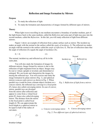
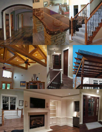
5.3 Gently pull down the front edge of the headliner and tuck the harness upunder the edge of the headliner.5.4 Continue tucking the harness under the headliner along the top of thewindshield working your way over to the driver's side "A" pillar. Dress theharness along the "A" pillar down to the dash opening.NOTE: It will probably be necessary to tape these wires in place,or wire tie them to the existing factory harness.Fig. 5.4Wire ColorBlackRedYellowBrownConnectionGround Wire 12V supply switched by ignition 12V constant power (battery)Connected to 12V dome light circuit
6.0 GROUND WIRE CONNECTION6.1 Locate an existing bolt or screw that is in contact with the vehicles metalbody in the area of the driver's step well.6.2 Route the mirror ground wire (black) to the ground point.6.3 Remove the bolt or screw from the ground point and install the ring terminal over the groundbolt/screw. Scrape off paint from mounting surface, if necessary, to obtain a solid connection.6.4 Reinstall and tighten the fastener.7.0 12-VOLT (POSITIVE) WIRE CONNECTION7.1 Route the 12-volt red wire to an ignition controlled wire.NOTE: If mirror remains on at all times, it could eventually drain the car's battery.7.2 Power source - Using a multi-meter, check for wire exiting fuse block that tests positive forbeing controlled by the ignition switch. The power must turn off when the ignition is in the OFFposition.7.3 Expose some vehicle wiring by slicing open some of the insulation and connect the red ignitionwire at this time. Use electrical tape to insulate and protect the connection. You may need to remove thebutt connector and strip some insulation from the Gentex harness. See examples of a good connectionon the following pages. Yellow wire (constant power source) is shown in the example.NOTE: Each vehicle is different. Always use a multi-meter and double check before makingany connections. If you are not familiar with vehicle wiring please consult a professional.**READ** - If you are installing a standard mirror, proceed to step 10.0. If you areinstalling a mirror with outside temperature, continue with step 9.0.
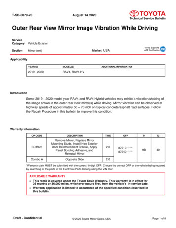
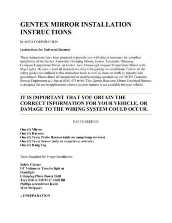
9.0 ROUTING THE TEMPERATURE HARNESS (inside the engine compartment)9.1 Open the hood of the vehicle.9.2 Locate the temperature sensor portion of your harness. It is the section with the green wires.9.3 Locate a grommet in the firewall near the interior harness location and remove it.NOTE: If a grommet is not available, drill a 9/16" hole in a safe andconvenient place to feed the 2-pin connector through. Takecare not to cause damage to objects in the passengercompartment when drilling.9.4 Locate the temperature probe harness and lay it out with the 2-pin connectortoward the firewall. Pass this connector through the hole or grommet accessto just inside the passenger compartment.NOTE: It is important that the 2-pin connector be inside the vehicle toprevent moisture from coming in contact with it.9.5 Route the rest of the harness towards the front of the vehicle over the fender well to an areain front of the radiator.NOTE: The preferred location for the temperature probe is in the centerof the grille or some place where it will be in free air in front,or to the side, of the radiator. Down near the bumper may alsobe used. Avoid locating it inside or in front of the wheel well,engine compartment, or too close to the headlamps. Try tokeep the height no higher than the center of radiator, andno lower than 8" above the pavement. Always try to keep thetemperature probe in the center of the vehicle; never locateit outside of the frame rails.
Fig. 9.59.6 Locate the temperature sensor probe.9.7 Plug the probe on the connector making sure that the gray moisture sealseats inside the probe collar.9.8 Clip on the temperature sensor probe. Do not install it pointing toward therear of the car or pointing downwards, as water may get past the connectorseals. Pull the excess temperature sensor harness back into the enginecompartment.9.9 Use wire ties to secure the temperature sensor harness.NOTE: Take care to route away from the accelerator and brake areaso that the harness does not in any way interfere with theiroperation.9.10 Find the grommet that was removed in order to feed the temperaturesensor harness through the firewall. Using a knife, carefully slit thegrommet and slide the wires into the grommet and reinstall the grommetback to is original position in the firewall.9.11 If you have not already plugged the temperature sensor harness into themain power harness mating plug, do so at this time.**Read** - If you are installing a 50-9050549001M, proceed to step 12.0.If you are installing a 50-9050620001M, continue with step 10.010.0 12-VOLT (POSITIVE) BATTERY WIRE CONNECTION10.1 Route the yellow wire labeled battery to a constant power source.10.2 Power source - Using a multi-meter, check for a wire at the fuse block
that tests positive for 12 volts. The power must be present when theignition is in the OFF position.11.0 MAP LIGHT WIRE CONNECTION11.1 There are two (2) types of dome light circuits used in automobiles.Type A. All General Motors, most Chrysler, and some Ford importvehicles use a circuit that puts a constant 12 volts to the dome light.When the door is opened, the door jam switch provides a path to groundand the light comes on. In this case the wire at the switch will have 12 volts when the door isclosed and 0 volts when the door is open.Type B. Most full-size Ford and some Chrysler vehicles use a circuit that has two wires at thedoor jam switch. When the door is closed, there is 12 volts on one wire but not the other. Whenthe door is open, there is 12 volts on both wires.11.2 Using a multi-meter, check the power at the door switch wire(s) anddetermine if the circuit is Type A or Type B. Contact your local auto dealership or auto soundcenter to obtain detailed information pertaining to your specific automobile wiring.11.3 Route the brown wire to a location so it can be connected to the proper wire at the doorswitch. The wire at the door switch must change from 12 volts to 0 volts or 0 volts to 12 voltswhen the door is opened or closed!11.4 Use a scotch lock or t-tap to connect the brown wire or butt connector.11.5 Test the map lights on the mirror and compare it with the vehicle's dome light. Both themap lights and dome lights should turn on and off together.11.6 If the mirror map lights work opposite of the dome light, open the black box connected tothe brown wire and change the position of the switch inside.NOTE: If the map light on the Gentex mirror does not turn off and youhave changed the position of the switch (11.6), disconnectbrown wire and repeat step 11.2.12.0 SECURING WIRE HARNESS
12.1 Now that all wires from temperature probe harness and the main harness have beeninstalled, they will need to be secured with wire ties." Under hood - be sure to keep wires away from moving parts suchas steering and brake mechanisms." Keep away from extremely hot engine components." Interior - wire tie all wires out of the way, making sure to avoidsteering and brake components.13.0 TESTING13.1 Turn the ignition switch to ON.13.2 With the vehicle in a fairly well lit area, perform the following:" Push and hold temperature switch for 15 seconds ON/OFF. Auto dimming is enabled whengreen LED is on." Cover the forward-looking photocell located on the back side of the mirror (a dark cloth ortowel will work)." After a few seconds, the mirror will begin to darken (the time may vary with ambient lightlevels)." Remove the cover from the forward photocell and the mirror will begin to clear." With car in garage facing back wall, shift into reverse with foot on brake." Mirror testing is now complete.14.014.1 You are now ready for final assembly of removed components and calibration of yourmirror. Operating instructions for your mirror are located on a hang tag provided with yourmirror kit.Complete Parts List Required for InstallationPart Number50-9053501M or50-9050549001Mor50-9053781M .C. Electronic Rearview Mirror - Alternating DisplayE.C. Comp Temp (Dual Display)E.C. Only MirrorE.C. Comp/Temp and Map LightsTemperature Sensor Harness (only on comp/temp mirrors)Temperature Sensor (must be used with the50-517GTEMP)Quantity111
72-101 or72-102 or72-11050-517102G or50-517198GHang Tag for Mirror Operations (Auto Dim)Hang Tag for Mirror Operations (Auto Dim/Comp/Temp)Hang Tag for Mirror Operations (Auto Dim/Comp/Temp/MapLights)1Wire Harness (2-pc) With Mounting Hardware1If you have any questions or comments regarding these instructions, please feelfree to contact MITO Corporation at 800-433-6486.
a mirror button kit, please contact your Gentex mirror retailer. 5.0 ROUTING OF THE GENTEX UNIVERSAL POWER HARNESS . NOTE: Locate the Gentex power harness. It will have a flat 7 or 10-pin connector which plugs into the mirror. 5.1 From the bottom of the driver's side dash, near the post location, feed this