Transcription
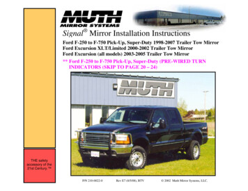
Signal Mirror Installation InstructionsFord F-250 to F-750 Pick-Up, Super-Duty 1998-2007 Trailer Tow MirrorFord Excursion XLT/Limited 2000-2002 Trailer Tow MirrorFord Excursion (all models) 2003-2005 Trailer Tow Mirror** Ford F-250 to F-750 Pick-Up, Super-Duty (PRE-WIRED TURNINDICATORS (SKIP TO PAGE 20 – 24)THE safetyaccessory of the21st Century. P/N 210-0022-0Rev E7 (8/5/08), BTV 2002 Muth Mirror Systems, LLC.
PROFESSIONAL INSTALLATION RECOMMENDEDWarranty does not cover damage to the vehicle or mirror housing due to improper installation. Muth Mirror Systems, LLC(MMS) assumes no responsibility with regard to the accuracy of this information. MMS assumes no liability or responsibilityresulting from improper installation, even in reliance upon this information. Proper installation is the responsibility of theinstaller. It is your responsibility to verify any circuit before interfacing with it using a digital multimeter.INCLUDED ITEMS:Please read instructions prior to installation.1 left and 1 right Signal mirror1 left and 1 right wire harness2 wire taps2 ring connectors1 instruction manualPROBLEMS OR QUESTIONS?Technical Assistance is available by callingMuth Mirror Systems Technicians at:REQUIRED TOOLS:1-800-844-6616Ratchet with extension or ratcheting screwdriver7mm socket10mm socket7/32” socketMedium slotted screwdriverWire crimper and stripperSmall pry barHeat gun (hair dryer)Masking tapeMultimeterSturdy glovesSafety glasses or gogglesMonday through FridayBetween 8:00 a.m. and 5:00 p.m. CSTOr through the Muth web site:www.muthco.comOr via E-mail: techsupport@muthco.com2
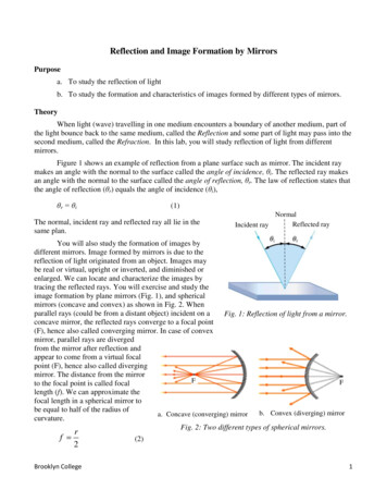
1231. Start with the driver’s side door and lower the window.2. Pull the plastic covering off from out of the corner of the door.3. Remove the tape from underneath the plastic covering.3
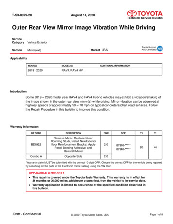
4564. Pry the window control panel out of the armrest. Start byprying from the top of the panel as shown.5. Disconnect all four wire harnesses from the window controlpanel.6. Remove the exposed screw to the right of the door handle.4
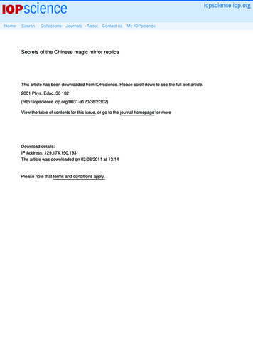
7897. Pry the door reflector out of the door panel. There is a notch onthe right side of the reflector where you can insert a medium slottedscrewdriver.8. Remove the screw from underneath where the door reflector usedto be.9. Lift the door panel up and off of the door. From behind the doorpanel, twist the door light socket about a half turn and pull it out ofthe door panel. Set the door panel aside.5
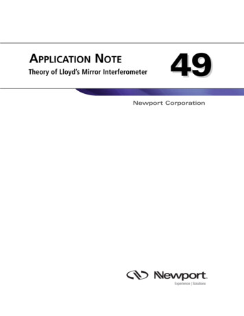
1110. Remove the four screws holding the speaker in place.11. Remove the speaker from the door and disconnect the wire. Setthe speaker aside.12. The mirror wire harness is secured to a wire bundle on the inside ofthe door with a plastic plug. Dislodge the plug and pull the wireharness slightly out of the speaker hole. Disconnect the mirror wireharness.10126
13141513. There are three rubber plugs in the corner of the door. Remove onlythe top and bottom rubber plugs to expose the mirror mounting nuts.14. Secure the mirror with one hand and remove the four mirrormounting nuts.WARNING! Be careful not to drop components into the doorcavity.15. Remove the mirror housing from the door.7
16WARNING! Safety glasses and sturdygloves are recommended for mirrorglass removal.16. Before the mirror can be removedfrom the mirror housing, two drive pinsneed to be dislodged from behind themirror. Press the top edge of the mirrorinto the housing to lift up the bottom edgeof the mirror and expose the bottom drivepin. Place the fork of a small pry bararound the neck of the drive pin.17NOTE: The neck of the drive pin islocated at the base of the mirror.17. Carefully twist the small pry bar untilthe head of the drive pin pops out of thesocket. Lift the bottom and outside edgesof the mirror further to expose theoutboard drive pin. Repeat the procedureabove to dislodge the outboard drive pin.8
191818. Once the drive pins are dislodged from the mirror, hold themirror housing in your lap. Push on the outer edge of the mirror topivot the mirror fully outward. Reach behind the mirror as shown.2019. Carefully pull the mirror out of the mirror housing. Disconnectthe heater wires if you have heated mirrors20. Carefully remove the foam insulation at the base of the mirror.NOTE: Pry up on the section of mirror housing that isdirectly above the existing mirror wire bundle.***ATTENTION*****For steps 21 to 31, please use the instruction thatpertains to your style of mirror.**9
Fixed Mirror (Non-telescoping)Telescoping Mirror212121. Use a small pry bar and remove the bottom mirror from themirror housing. (Be sure to place the pry bar tip under the center ofthe mirror as shown) It is held in place with a ball in the housingand a socket in the center of the mirror.21. There is a plastic housing that covers the base of the mirror.Unsnap the five tabs around the edge of the mirror base and slidethe housing away from the base.222222. The plastic housing behind the mirror needs to be removed.Unsnap the four tabs from the inside of the mirror housing.22. Remove the six screws that hold the two halves (front andback) of the mirror housing together.10
Fixed Mirror (Non-telescoping)Telescoping Mirror232323. After the tabs have been unsnapped, slide a small pry bar inbetween the two halves of the mirror housing. Twist the pry baruntil the two halves of the mirror housing separate. Set the backhalf of the mirror housing aside.23. Lift the front half of the mirror housing off of the back half.Turn it 90 degrees so that you have access to the bottom portion ofthe mirror housing.242424. The wire harness will be routed through the top support bar onthe mirror housing. Using the shorter of the two harnesses from thewiring kit, guide the end with the mating connector into the hole onthe swivel joint (1). Feed the wire into the hole until about sixinches of wire protrude out of the opposite end (2). Guide the endwith no mating connector into the hole next to the purple-coatedstabilization bar (3). Remove any slack in the wire harness.24. There is a plastic housing that covers the base of the mirror.Unsnap the five tabs around the edge of the mirror base and slidethe housing away from the base.11
Fixed Mirror (Non-telescoping)Telescoping Mirror252525. The wire harness will be routed through the bottom support barin the mirror housing. Using the shorter of the two harnesses fromthe wiring kit, guide the end without the mating connectorunderneath the bottom mirror mount and into the support bar.25. Set the factory mirror assembly on a clean flat surface. Using asmall pry bar, remove both black friction pins from the back of thefactory mirror assembly.262626. Set the new Signal mirror on a clean flat surface. The frictionpins go in the top and outside holes on the back of the mirrorassembly. Using even pressure, snap the drive pins into position.26. Leaving about six inches of wire in the mirror housing, guidethe wire harness along the existing factory wire harness. Removeany slack in the wire.12
Fixed Mirror (Non-telescoping)Telescoping Mirror272727. Set the factory mirror assembly on a clean flat surface. Using asmall pry bar, remove both black friction pins from the back of thefactory mirror assembly.27. Push the white drive pins down until they bottom out in themotor mount. Align the nub on the top drive pin so that it pointsdirectly down. Align the nub on the bottom drive pin so that itpoints to the outside edge of the mirror housing. The direction forthe nubs on both drive pins should be perpendicular to each other.WARNING! The drive pins must be aligned or else the newSignal mirror will not mount correctly. Guide the wireharness through the circular opening next to the drive pins.282828. Position the back half ofthe mirror housing and secure itinto place by applying eventhumb pressure around thesnaps as shown. Then snap theplastic housing over the base ofthe mirror and replace the foaminsulation.28. Set the new Signal mirror on a clean flat surface. The frictionpins go in the top and outside holes on the back of the mirrorassembly. Using even pressure, snap the drive pins into position.13
Fixed Mirror (Non-telescoping)Telescoping Mirror292929. Push the white drive pins down until they bottom out in themotor mount. Align the nub on the top drive pin so that it pointsdirectly down. Align the nub on the bottom drive pin so that itpoints to the outside edge of the mirror housing.29. Connect the Signal mirror mating connector to the Signal mirror wire harness. Connect the heater wires if you have heatedmirrors. Place the Signal mirror over the mirror housing. Guidethe top friction pin into its socket and move the Signal mirrorcloser to the mirror housing. Ensure that all 4 anti-vibration tabsare within the mirror housing before aligning friction pins andcenter hub. Guide the inboard friction pin into its socket. Align thecenter hub of the Signal mirror over the mirror mount.303030. Use the entire palm of your handand apply even pressure until theSignal mirror snaps into position.30. Connect the Signal mirror mating connector to the Signal mirror wire harness. Connect the heater wires if you have heatedmirrors.14
Fixed Mirror (Non-telescoping)Telescoping Mirror31a3131a. Place the Signal mirror over the mirror housing. Guide the topfriction pin into its socket and move the Signal mirror closer to themirror housing. Ensure that all 4 anti-vibration tabs are within themirror housing before aligning friction pins and center hub. Guide theinboard friction pin into its socket. Align the center hub of the Signal mirror over the mirror mount. Use the entire palm of your hand andapply even pressure until the Signal mirror snaps into position.31. Firmly press down on the outboard and bottom edges of theSignal mirror to snap it into the drive pegs. Press on all four sidesto ensure that the Signal mirror is fully seated into the mirrorhousing. Replace the plastic cover and foam insulation on themirror base.31b31b. Firmly press down on the outboard and bottom edges of theSignal mirror to snap it into the drive pegs. Press on all four sidesto ensure that the Signal mirror is fully seated into the mirrorhousing. Replace the plastic cover and foam insulation on themirror base.15
32. Guide the wire harnesses through the door and position the mirrorhousing assembly on the mirror mount. Bolt the mirror housing to themirror mount with the four mirror mounting nuts.32WARNING! Do not over tighten the mirror mounting nuts.Note: It is possible that your vehicle may be pre-wired for Signal mirrors.To determine this, verify whether there is a (driver side) green with whitestripe wire & a (passenger side) white with blue stripe wire in the doors. Ifyou locate these wires, probe to verify presence of current with turnindicator activated. If current is present, make connections as indicated onpage 18. If these wires are not present in the doors, then proceed with thefollowing instructions.Pull the rubber boot out from between the door and door frame. Pass thewire harness through the opening vacated by the rubber boot. Reconnectthe factory wire harness.3333. Pull the rubber boot off of the door frame and guide theharness through the rubber boot and into the vehiclethrough the door frame.16
3434. Repeat all of the previous steps to replace the factory mirror onthe passenger side door with the new Signal mirror. Guide theSignal mirror wire harness through the door frame and upunderneath the lower dash panel. Run the wire harness along to thedriver’s side lower dash panel.3535. To gain access to the vehicle’s electrical system, removethe lower dash panel from the steering column by removingthe four screws in each corner of the panel.17
3636. Locate the GREEN WITH WHITE STRIPE wire from within the wire bundle. Turn the ignition key so that electricalpower is on and activate the driver side turn indicator. Probe the wire with the wire tester to verify that flashing turn indicatorpower is present. Label that wire as ‘driver side turn’. Locate the WHITE WITH BLUE STRIPE wire from within the wirebundle. Activate the passenger side turn indicator and probe the wire with the wire tester to verify that flashing turn indicatorpower is present. Label that wire as ‘passenger side turn’.18
1234USE THE INCLUDED WIRE TAPS AND FOLLOW THE FOUR STEPS ABOVE TO SPLICE INTO THE TURN INDICATOR WIRES37. Make sure the harnesses are routed securely under the dash and enough slack is left for splicing.38. Splice the RED wire from the driver side harness into the green with white stripe wire previously labeled ‘driver side turn’.39. Splice the RED wire from the passenger side harness into the white with blue stripe wire previously labeled ‘passenger side turn’.40. Strip and twist together the ends of the black wires from each harness. Crimp them together in the supplied ring connector andground to a suitable nearby location on the metal framework of the vehicle.41. Activate each turn indicator to verify that the Signal mirrors are working.42. Replace the lower dash panel, speakers, door panels, and all accessories.Muth products are protected by these, and other pending, United States 19,3755,788,357 6,005,724 6,045,243 6,076,948 6,257,746 6,700,123 6,749,325 6,918,685 7,008,091 7,015,642 7,104,676 28,372D428,373D428,842D429,202D430,088D394,83319
Ford F-250 to F-750 Pick-Up, Super-Duty (PRE-WIRED TURN INDICATOR)Signal mirror replacement(Mirror replacement does not require mirror head to be removed from vehicle)BAWARNING! Safety glasses and sturdy gloves are recommended formirror glass removal.A. Before the mirror can be removed from the mirror housing, two drivepins need to be dislodged from behind the mirror. Press the top edge ofthe mirror into the housing to lift up the bottom edge of the mirror andexpose the bottom drive pin. Place the fork of a small pry bar around theneck of the drive pin.NOTE: The neck of the drive pin is located at the base of the mirror.B. Carefully twist the small pry bar until the head of the drive pin pops outof the soczket. Lift the bottom and outside edges of the mirror further toexpose the outboard drive pin. Repeat the procedure above to dislodgethe outboard drive pin.C. Heat the OE mirror, in a circular motion, for 15-25 seconds with a heatergun to help loosen the mirror backing plate.20
Ford F-250 to F-750 Pick-Up, Super-Duty (PRE-WIRED TURN INDICATOR)Signal mirror replacement continuedDEFD. Push in on the upper inboard edge of the large OE mirror to pivot thelower outboard edge fully outward. NOTE: The mirror is held inplace with a ball in the housing and a socket in the center of the OEmirror. With a glove hand, grab the lower outboard edge of the OEmirror and carefully pull until OE mirror pops off. If heated,disconnect heater wires from the back of the OE mirror and remove OEmirror.E. Remove the (2) white motor pins. Careful, not to loose the spring clipsinside motor pins. Remove the dust boots and discard.F. Using a utility knife, carefully cut the electrical tape around the wirebundle within the mirror housing.21
Ford F-250 to F-750 Pick-Up, Super-Duty (PRE-WIRED TURN INDICATOR)Signal mirror replacement continuedGHIG. DRIVER SIDE: Locate the LIGHT GREEN (HOT) wire and the BLACK (GND) wire within the wire bundle. Turn the ignition keyso that electrical power is on and activate the driver side turn indicator. Probe the wire with the wire tester to verify that flashing turnindicator power is present. Label LIGHT GREEN wire as ‘driver side turn’.PASSENGER SIDE: Locate the WHITE (HOT) wire and the BLACK (GND) wire from within the wire bundle. Activate thepassenger side turn indicator and probe the wire with the wire tester to verify that flashing turn indicator power is present. Label theWHITE wire as ‘passenger side turn’.H. NOTE: For splicing into the turn directional indicator wires, a variety of options can be perform such as soldering, using wiretaps, using T-Taps, etc. These diagrams showed the connections are made using T-Taps (not supplied with Signal mirrorkit). These T-Taps wiring kits can be purchase from various autopart or hardware stores. Otherwise, use whichever methodyou preferred to splice the new Signal mirror harnesses to the turn directional indicator wires. Splice into the driver side turnand the BLACK wires using T-Taps to make the connection. Repeat step for passenger side turn.I. Insert all (4) white motor pins into their respective sockets on the mirror mount of the new Signal mirror.22
Ford F-250 to F-750 Pick-Up, Super-Duty (PRE-WIRED TURN INDICATOR)Signal mirror replacement continuedJLKMJ. Locate one of the two supplied Signal mirror harnesses, cut the end with the molexconnector to about 4 – 6 inches. Split the wires up and strip about 1/4 inch off of both ends.Insert and crimp the stripped ends into the spade connectors as shown. Give the crimped endsseveral tugs to ensure wires are securely in place.K. Insert the RED wire spade connector into the driver side turn T-Tap. Repeat process for theBLACK (GND) wire.L. Connect the Molex connectors on the new Signal mirror and the new Signal mirrorharness. If heated, reconnect the heater wires to the heater terminals on the back of the newSignal mirror. NOTE: There is no polarity on the heater wires so they can beinterchange.M. Tuck all wiring connectors and wires inside mirror housing access hole, if possible. Positionthe new Signal mirror over the center nub of the mirror housing. Align and insert all (4)white motor pins into there respective slots on the mirror housing. Slowly push in the middleof the new Signal mirror until the new Signal mirror snaps into place. Press down on allsides to ensure proper engagement and function. CAUTION: Improper Signal mirrorassembly could result in Signal mirror falling off.23
T-TAPS (NOT INCLUDED IN KIT) SPLICING PROCEDURE – FOLLOW THE 4-STEPDIAGRAMS ABOVE TO SPLICE INTO THE TURN INDICATORS AND GROUND WIRESWIRE TAPS (SUPPLIED WITH KIT) SPLICING PROCEDURE – FOLLOW THE 4-STEPDIAGRAMS ON PAGE-19 TO SPLICE INTO THE TURN INDICATORS AND GROUND WIRES24
Unsnap the five tabs around the edge of the mirror base and slide the housing away from the base. 22. The plastic housing behind the mirror needs to be removed. Unsnap the four tabs from the inside of the mirror housing. 22 21 Fixed Mirror (Non-telescoping) Telescoping Mirror 21. Use a small pry bar and remove the bottom mirror from the mirror .