Transcription
APPLICATION NOTETheory of Lloyd’s Mirror Interferometer49Newport Corporation
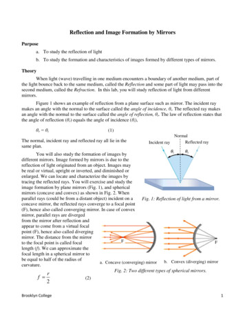
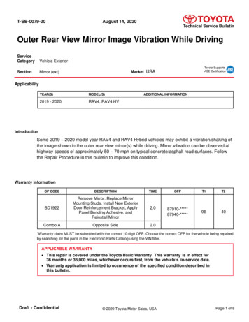
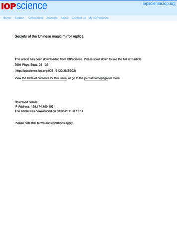
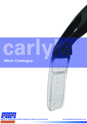
INTRODUCTIONCThere are two principal methods for producing coherentsources for interferometry. One uses the division ofwavefront, as in the Young’s double slit experiment. Thesecond divides the amplitude between two arms, as in theMichelson interferometer. The Lloyd’s Mirror approach useswavefront division at a mirror to produce two-sourceinterference patterns. The basic setup is shown in Figure 1.This was first described by English physicist Humphrey Lloydin 1834.View Screenor TargetSource, SADEBFFigure 2Now it’s time to do the math. We need to derive an expressionfor the intensity of the light at any point on the observationscreen. The theory that we have here is very similar to thetheory for Young’s double-slit interference, which you can findin many standard optics texts, such as Jenkins and White1 orHecht.2 We start with two waves of light emerging from ourreal source S and appearing to emerge from our virtual sourceS’, separated by a distance d, which we assume to be small.Figure 3 is a repeat of Figure 1, but with more detail for thedevelopment of the theory.View Screenor TargetMirrorDVirtual Source, S’PFigure 1Source, SA source, S, emits coherent light into a cone such that someof the light follows a path that goes directly to the target whilelight emitted at a higher angle reflects from the mirror andupon reflection also goes to the target. The light reflectedfrom the mirror then appears to have come from a virtualsource, S’. When the light from the two paths is in phase abright fringe appears and when the light is out of phase a darkfringe appears at the target.xθθdMirrorΔVirtual Source, S’Figure 3THEORY OF THE LLOYDʼS MIRRORINTERFEROMETERThe two sources, real (S) and virtual (S’), become analogs forthe two slits in Young’s double-slit experiment. In 1801, Youngdemonstrated the interference of light, thereby establishingits wave nature. In 1803, he presented a paper to the RoyalSociety demonstrating two-slit diffraction. Young’s originalsketch, based on his observation of water waves, is shown infigure 2. He showed that the pattern formed by light at anobservation screen is exactly analogous to the pattern shownfor water waves.The distance from the sources to the screen is D. The twowaves are superimposed on the screen at a point P at somedistance, x, from the center line, which is defined by the centerbetween the two sources, which in turn is the plane of themirror. The intensity at P is determined by the phasedifference between the two waves, and that phase difference isrelated to the path length difference, . The angle q is equalto x/D, but that is also equal to /d, by reference to similartriangles. The phase difference will be the wavenumber timesthe path length difference. However, in the Lloyd’s mirror,there is an extra phase shift of at the reflection from themirror surface that we would not have in Young’s double-slit,which we must take into account in our calculations. Thatphase difference, explicitly including the extra phase shift of upon reflection, is then:δ kΔ 2 d sin θ – λ2
The intensity at the point P will be the square of theamplitude, A, which is the sum of that contributed by the twobeams, each with amplitude a.I A2 2a2 (1 cos ) 4a2 cos2( 2 )the virtual second source S’ also moves farther from the mirror(down in the figure). So, the distance d is increased by anamount that is two times the distance that S has been moved.From our equation for the positions of the bright fringes, wesee that increasing d reduces the distance between thosebright fringes. As d increases we can produce finer and finerfeatures in the interference pattern.We can write as:x 2 d– λDSo, we will have bright fringes when:x (m 1/2) λ DdWe have a bright fringe for any integer, m, meeting thiscondition. This development is for the two-dimensional case,analogous to Young’s experiment, where we only consider thephase shift in the plane, resulting in a one-dimensional linefor the fringe pattern. The theory can be extended to threedimensions to give us a two-dimensional pattern on thescreen. That is beyond the scope of this Application Note, butthe development of the theory in three dimensions to yield atwo degree-of-freedom Lloyd’s Mirror interferometer patterncan be found in Reference 3.In this development of the theory, we have not made anyassumption about the intensity of light from each source.Because the virtual source at S’ is due to a reflection in amirror, the intensities from the two sources will not be thesame. If the intensity from S is equal to I1, then the intensityfrom the virtual source S’ will be I2 R x I1, where R is thereflectivity of the mirror. Since we are dealing with twosources that are ideally monochromatic point sources, thepredicted visibility is.4,5,6Visibility (ideal) 2 I1I2I1 I2In practice, even with, for example, an aluminum mirror withR 80% in the UV, the loss of visibility will be small and thevisibility would be approximately 99% of the ideal maximum.However, the spectral range employed may in some casesrestrict the reflectivity that can be realized, and thereby thevisibility that can be achieved, using commercially-availablemirrors.If we increase d in a standard double-slit interference, we alsohave to expand the input beam so that it covers both slits.This results in a large loss of power since all the light incidenton the barrier between the two slits is lost. However, usingthe Lloyd’s mirror technique, increasing d does not result inadditional power loss since the second “slit” is just the virtualimage of the source in the mirror. Therefore, the Lloyd’smirror technique is powerful in that we can achieve very smalldetails in the interference pattern while maintaining thepower level that is needed for applications that require highlight levels, such as photolithography.One of principal advantages of the Lloyd’s mirror technique isits simplicity. The increase or decrease of the separation d canbe simply achieved by rotating the system of mirror and targetwith respect to the laser source. Once the laser and itsfocusing optics are in place, they do not need to be changedto control the pattern formed at the target. Only one degreeof control, the adjustment of a rotation stage, is all that isrequired. We will look at that in more detail in a later section(Equipment) of this note.APPLICATIONS:INTERFERENCE LITHOGRAPHYThe most common current application of the Lloyd’s mirrortechnique is in UV photolithography and nanopatterning.This interference lithography (IL) technique has been used tocreate periodic nanoscale patterns on relatively largesubstrates. 3 and references therein This lithographic technique relies onconstructive and destructive interference to write a pattern ina photoresist film. Surface patterning using IL has beenshown to increase the incident light in absorber layers ofGaAs.7POWER OF THE TECHNIQUEImprovement of the biofunctionality in implants usingnanofeatures generated by IL has been explored in titaniumimplants.8 The IL technique using a Lloyd’s mirror has alsobeen used to write directly in alkylphosphonates adsorbed onoxides of titanium to produce nanostructured polymermonolyaers.9Let’s go back and look again at Figure 3. If we move the sourceS farther from the mirror (that is, up in the figure), we see thatAlthough this work is usually done in the UV portion of thespectrum, the Lloyd’s mirror IL technique has been extendedto the visible at 405 nm,10 and to the extreme UV at 46.9 nm.113
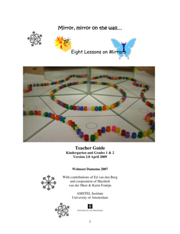
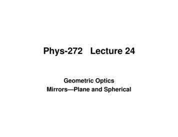
OTHER APPLICATIONSWhile interference lithography is the most commonapplication, the Lloyd’s mirror interferometer has been usedin a wide range of applications. A sampling of theseapplications LensFigure 4a Direct measurement of MTF (modulation transfer function)of CCD’s.12Target Manufacturing of Fiber Bragg gratings using phase plates.13 Laser diode beam shaping.14PlaneWaveFrontLaserSpatialFilter Compact Fourier transform wavemeter for pulsed lasers.15Mirror Laser-plasma diagnostics (in the extreme UV).16Figure 4bEQUIPMENTAs described above, most applications of the Lloyd’s mirrormake use of a UV laser. The optical components chosen in thelist shown here are intended for use with a HeCd laser at 325nm or a tripled (355 nm) or quadrupled (266 nm) Nd:YAGlaser. Two basic options for the experiment are illustratedschematically in Figure 4; Figure 4a showing the setup with acollimating lens and Figure 4b showing the setup without acollimating lens. The trade-offs associated with these twoversions of the system are discussed below at the collimatinglens assembly.Lloyd’s mirror interferometer assembly:Spatial filter assembly:For an in-depth discussion of spatial filtering, please refer tothe Technical Note, Spatial Filters, at our 3/content.aspx. 910AU-27X910PH-5SP-3VPH-3-PPS-FCollimating lens assembly:This collimating lens may be eliminated if the experimentrequires expansion of the beam to a large diameter. If thetarget has a small area, the version in Figure 4a using acollimating lens will result in a higher power density per unitarea of the target. A large beam diameter will be achievedusing the setup without the collimating lens in Figure 4b. Thisallows wider coverage but will also reduce the power densityper unit area requiring longer exposure times. SPX055AR.10 (f 300 mm)LH-1SP-3VPH-4-PPS-F20SD520AL.2(The mirror included here is a 2” square UV-enhancedaluminum mirror. This mirror is designed for use in theUV portion of the spectrum and has a large area that isuseful in UV lithographic nanopattern applications.) V100-P22x PS-32x PS-0.25UTR80S CYM-2R2x PS-F38M-PBN8Mirror assembly (2x):This mirror assembly for steering the beam from the laser tothe interferometer is optional, depending upon the spacerequirements of the experimental setup on the optical table. 10D20RM.2 SP-3 PS-F U100-A2K VPH-4-P4
ACKNOWLEDGMENTNewport Corporation wishes to acknowledge and thank Mr. Ishan Wathuthanthri, Stevens Institute of Technology, MechanicalEngineering Department, Hoboken, NJ, for his consultation, criticism, and kind assistance in the preparation of this application note.NOTESThe references cited in this list provide a background for understanding the Lloyd’s mirror interferometer. The referencesincluded here present a sampling of the literature that is available, but this list is not intended to be an exhaustive survey ofpublished research.1. Francis A. Jenkins and Harvey E. White, Fundamentals of Optics, chapter 13, McGraw-Hill.2. Eugene Hecht, Optics, section 9.3, Addison-Wesley.3. Ishan Wathuthanthri, Weidong Mao, and Chang-Hwan Choi, Two degrees-of-freedom Lloyd-mirror interferometer for superior patterncoverage area, Opt. Lett. 36, No. 9, p. 1593 (May 1, 2011)4. bility.html5. http://en.wikipedia.org/wiki/Interferometric visibility6. Hecht, reference 2 above, sections 12.2 and 14.37. Kyung Seok Cho, et al., Improved efficiency in GaAs solar cells by 1D and 2D nanopatterns fabricated by laser interference lithography,Opt. Comm 10-11, 2608, (15 May 2011)8. M. Domanski, et al., Novel approach to produce nanopatterned titanium implants by combining nanoimprint lithography and reactive ionetching, 14th International Conference on Miniaturized Systems for Chemistry and Life Sciences, 3-7 October 2010,Groningen, The Netherlands9. G. Tizazu, et al., Large area nonpatterning of alkylphosphonate self-assembled monolayers on titanium oxide surfaces by interferometriclithography, Nanoscale 3, No. 6, p. 2511 (June 2011)10. Ikjoo Byun and Joonwon Kim, Cost-effective laser interference lithography using a 405 nm AlInGaN semiconductor laser, J. Micromech.Microeng. 20 055204 (23 April 2010)11. P. W. Wachuluk, et al., Nanopatterning in a compact setup using table top extreme ultraviolet lasers, Opto-Electron. Rev. 16 No. 4, p.444 (2008)12. E. B. Hochberg and N. L. Chrien, http://hdl.handle.net/2014/26078 (June 8, 1996)13. Christophe Martinez, et al., Phase Plate Process for Advanced Fiber Bragg Gratings Devices Manufacturing, IEICE Trans. Electron.,E83-C, No. 3 (March 2000)14. Takehiro Fukushima, et al., Laser Diode Beam Shaping by Optical Interference, Opt. Rev. 18, No. 3, p. 287 (2011)15. John Kielkopf and Lawrence Portaro, Appl. Optics, 31 No. 33, p. 7083 (1992)16. H. Merdji, et al., Coherence properties of high-order harmonics: Application to high-density laser-plasma diagnostics, Laser and ParticleBeams, 18, p. 495 (2000)5
Newport CorporationWorldwide Headquarters1791 Deere AvenueIrvine, CA 92606(In U.S.): 800-222-6440Tel: 949-863-3144Fax: 949-253-1680Email: sales@newport.comVisit Newport Online at: www.newport.comThis Application Note has been prepared based on development activities andexperiments conducted in Newport’s Technology and Applications Center and the resultsassociated therewith. Actual results may vary based on laboratory environment andsetup conditions, the type and condition of actual components and instruments usedand user skills.Nothing contained in this Application Note shall constitute any representation orwarranty by Newport, express or implied, regarding the information contained herein orthe products or software described herein.Any and all representations,warranties and obligations of Newport with respect to its products and software shall beas set forth in Newport’s terms and conditions of sale in effect at the time of sale orlicense of such products or software. Newport shall not be liable for any costs,damages and expenses whatsoever (including, without limitation, incidental, special andconsequential damages) resulting from any use of or reliance on the informationcontained herein, whether based on warranty, contract, tort or any other legal theory, andwhether or not Newport has been advised of the possibility of such damages.Newport does not guarantee the availability of any products or software and reserves theright to discontinue or modify its products and software at any time. Users of theproducts or software described herein should refer to the User’s Manual and otherdocumentation accompanying such products or software at the time of sale or license formore detailed information regarding the handling, operation and use of such productsor software, including but not limited to important safety precautions.This Application Note shall not be copied, reproduced, distributed or published, inwhole or in part, without the prior written consent of Newport Corporation.Copyright 2012 Newport Corporation. All Rights Reserved. The Newport “N” logo is a registered trademarks of Newport Corporation.Newport Corporation, Irvine, California, has been certifiedcompliant with ISO 9001 by the British Standards Institution.DS-0912016
Lloyd's mirror interferometer assembly: Laser Spatial Filter Collimating Lens Target Mirror 20SD520AL.2 (The mirror included here is a 2" square UV-enhanced aluminum mirror. This mirror is designed for use in the UV portion of the spectrum and has a large area that is useful in UV lithographic nanopattern applications.) † V100-P2 † CYM-2R