Transcription
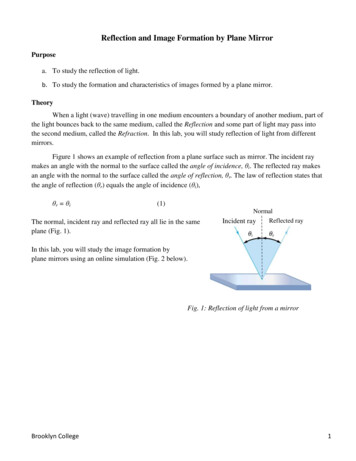
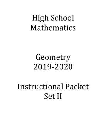
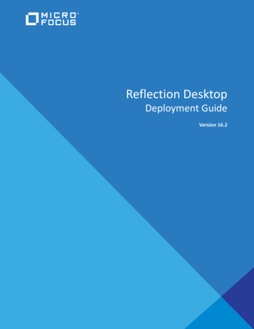
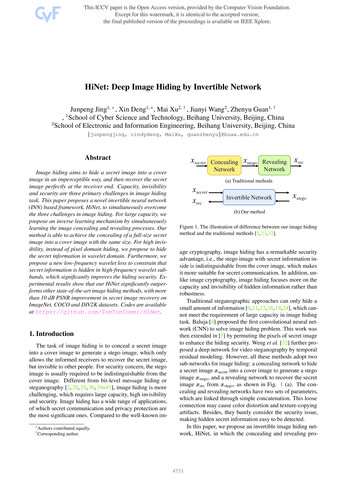
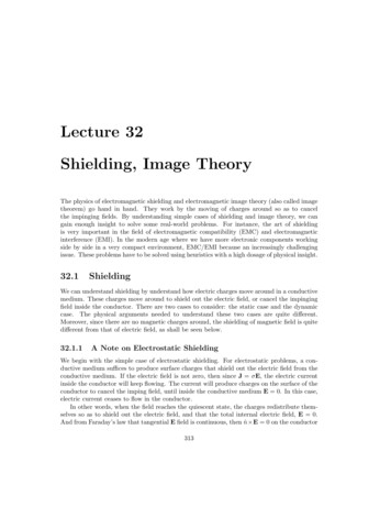
Reflection and Image Formation by MirrorsPurposea. To study the reflection of lightb. To study the formation and characteristics of images formed by different types of mirrors.TheoryWhen light (wave) travelling in one medium encounters a boundary of another medium, part ofthe light bounce back to the same medium, called the Reflection and some part of light may pass into thesecond medium, called the Refraction. In this lab, you will study reflection of light from differentmirrors.Figure 1 shows an example of reflection from a plane surface such as mirror. The incident raymakes an angle with the normal to the surface called the angle of incidence, θi. The reflected ray makesan angle with the normal to the surface called the angle of reflection, θr. The law of reflection states thatthe angle of reflection (θr) equals the angle of incidence (θi),θr θi(1)The normal, incident ray and reflected ray all lie in thesame plan.NormalReflected rayIncident rayYou will also study the formation of images bydifferent mirrors. Image formed by mirrors is due to thereflection of light originated from an object. Images maybe real or virtual, upright or inverted, and diminished orenlarged. We can locate and characterize the images bytracing the reflected rays. You will exercise and study theimage formation by plane mirrors (Fig. 1), and sphericalmirrors (concave and convex) as shown in Fig. 2. Whenparallel rays (could be from a distant object) incident on aFig. 1: Reflection of light from a mirror.concave mirror, the reflected rays converge to a focal point(F), hence also called converging mirror. In case of convexmirror, parallel rays are divergedfrom the mirror after reflection andappear to come from a virtual focalpoint (F), hence also called divergingmirror. The distance from the mirrorFFto the focal point is called focallength (f). We can approximate thefocal length in a spherical mirror tobe equal to half of the radius ofb. Convex (diverging) mirrora. Concave (converging) mirrorcurvature.Fig. 2: Two different types of spherical mirrors.f r2Brooklyn College(2)1
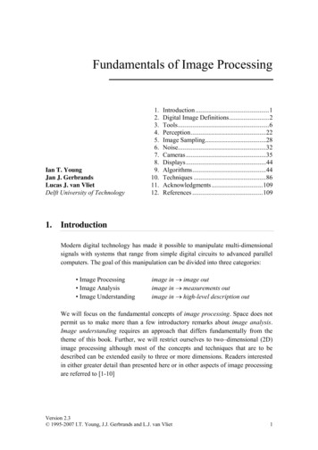
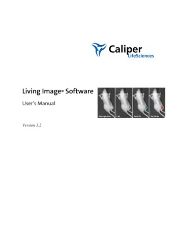
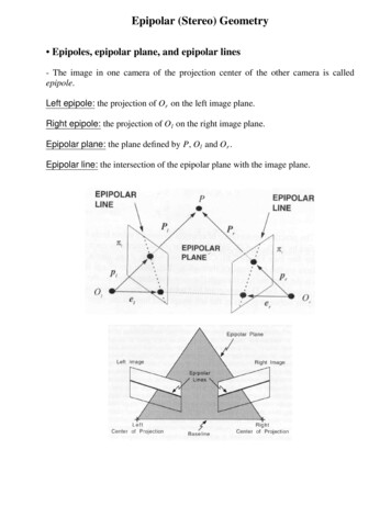
For spherical mirrors, relation between object distance (do), image distance (di) and focal length(f) is given by mirror equation1 1 1 do dif(3)where do, di and f are measured from the mirror on the principal axis. The magnification of the image isgiven bym hid ihodo(4)Both relations given in Eq. (2) and (3) hold for concave as well as convex mirrors. Focal lengthfor concave mirror is taken as position and for convex lens is negative. Follow the sign convention usedin your text book.Figure 3 illustrates how images are formed by a plane mirror and curved mirrors. Consider apoint ‘O’ on an object. The rays of light coming from the point reflect according to the laws ofreflection. Out of several possible rays from the point, we need at least two rays to locate the image. ForOOnormalIOIdidoa. Plane mirrorIb. Convex mirrorc. Concave mirrorFig. 3: Image formation by (a) plane (b) convex and (c) concave mirrors.a plane mirror, as shown in Fig. 3a, the normals are parallel for both incident rays, so they reflect withdifferent angles of reflection. The reflected rays upon incident on our eye see the image. Intersection ofthe reflected rays is the position of image. However, the reflected rays do not intersect as they arediverged. We have to back trace the reflected rays (by dotted lines) to find the intersection, I. Our eyessee as if the light is coming from the point I behind the mirror. Thus, it is a virtual image. Note theobject distance (do) and image distance (di) is same in plane mirrors. For such case the magnification is1 from Eq. (3). That’s why you see your identical image on the mirror. But why does your right handbecome left hand and vice versa in mirror?For convex mirror as shown in Fig. 3b, the reflected rays are again diverged and form a virtualimage at I. Note that the image distance is different from the object distance. What do you expect themagnification? For concave mirror shown in Fig. 3c, the reflected rays indeed converge at point I (noback trace needed) which is the image position. Thus, it forms a real image. The rays shown in concaveBrooklyn College2
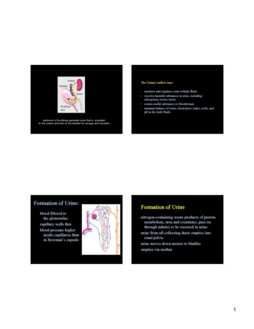
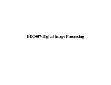
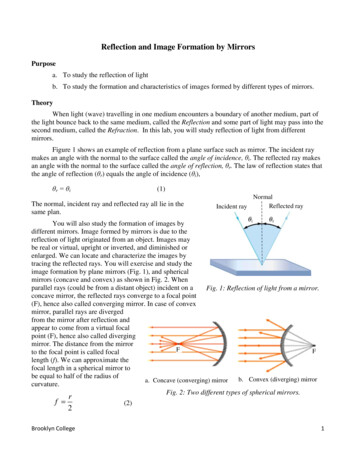
mirrors are special rays- one parallel to principal axis (P ray), one passing through focus (F ray) and onereflected from the center of mirror. Depending upon the position of the object, image formed by aconcave mirror could be real or virtual and could also be magnified or diminished.ApparatusPlane mirror with holder, pair of compasses, concave-convex cylindrical mirror, scale, protractor, pins,pin board, paper, laser light.Description of ApparatusSafety precautions**** Do not look directly into laser beam ******* Do not shine the laser light at your lab partners and take special care to avoid the eyes ***** Turn off the laser when not in use **Plane mirrorCylindricalmirrorProtractorCompassRed laserFig. 4: Apparatus for this labApparatus used in this lab are shown in figure 4. The beam of a laser is used to trace thedirection of light. Plane mirror is a simple glass mirror. Concave-convex cylindrical mirror is made bymetal and it has reflecting surface on both sides. So we can use it for concave or convex purpose.ProcedureIn this exercise and all through your work in optics, represent the actual path of all rays of lightby solid lines and represent virtual rays (prolongations of actual ray paths) by broken lines. Opticalsurfaces should be represented by heavy solid lines.Prepare a pencil as sharp as possible. The successfulness of this lab strongly depends on thesharpness of your pencil and your carefulness when you mark dots or draw lines with your pencil.Brooklyn College3
Part I. Plan mirror(a) Reflection of light by plane mirror1. Place a sheet of paper on the cork board, and draw a straight line near the top of the paper. Thisis the "mirror line". Set up the plane mirror in its holder on the mirror line so that the actualmirror surface is on the line. Adjust the mirror carefully so that the mirror is parallel to line.2. Place the laser on the bench table, not on the cork board. Turn on the laser and shoot thebeam to the mirror with an arbitrary angle. You should see the reflected beam. Mark two dotsabout 10 cm apart on the paper along the path of the incident beam. You may label both pointsby 1. Similarly, mark two dots on the reflected beam. You may label these points by 1’.3. Repeat the previous step with the laser beam shooting at another point on the mirror and anotherarbitrary angle. You may label 2s for this second trial. TURN OFF the laser.4. Now, remove the mirror and draw straight lines joining the dots of the same label up to mirrorline and mark arrows to show the incident and the reflected beam for both trials. Do the tworeflected and incident beams converge on the mirror line?(b) Image of a point object formed by plane mirror1. Flip the sheet of paper for this part (or use a new sheet) and mark the mirror line across thecenter of a sheet and place the plane mirror on the line as before. Mark a point ‘O’ about 10 cmin front of the mirror roughly in the center of space. This point will serve as a point object. Canyou see the image of the point in the mirror?2. Now, shoot the laser beam to one half side ofthe mirror through the point O as shown inFig. 5 and mark two points (one near themirror and another about 10 cm apart) on thepath of the reflected beam. You may labelthem as (1) and (1).3. Remove the laser beam and shoot the laserbeam to anther half side of the mirrorthrough the point O again. As before, marktwo points on the path of the reflected beam.You may label them as (2) and (2). Turn offthe laser.IMirror211Back traced linesO2Laser beamReflected ray4. Now, remove the mirror. Draw the reflectedLaserrays joining these points, i. e., (1) and (1),and (2) and (2) all the way up to the mirrorFig. 5. Laser beam for tracing rays.line and mark arrow on each. Back trace thetwo paths of the reflected beam withdotted lines in the area behind the mirror line until they intersect at a point, I. The point I is theimage of the point object O formed by the mirror. Draw a dotted line connecting the point O andI. Measure the angle between the mirror line and the line O-I. What should this angle be? If yourresult is more than 10 degrees away from the expected value, repeat the procedure!Brooklyn College4
(c) Image of a line formed by a plane mirror1. Use a new sheet of paper. Randomly draw a 5 cm long straight line O-O' (not parallel to themirror) about 10 cm in front of the mirror. O and O’ are extreme points of the line.2. To find the image of point O, repeat steps b2 – b3 using point O as an object.3. Now, to find the image of point O’, repeat steps b2 – b3 using point O’ as an object.4. Remove the mirror and determine the corresponding image points I and I’ for object points Oand O’ as you did in step b4. Draw a line by connecting the points I and I’. This line is the imageof the line O-O’ in front of the mirror. Is this image virtual or real?Part II. Image formation by Curved Mirrors(a) Concave cylindrical mirror1. On another sheet draw curved mirror line of the concave cylindrical mirror (not the convex side)near the top of the paper. Mark the center point P on the curved mirror line and determine thecenter of curvature for this mirror. You may use one of the following methods.Method 1: Using a compass draw a chord of radius about 5 cm from the point P to intersect attwo points on the curved mirror line. From these two intersection points, draw two perpendicularbisectors by drawing chords on the concave mirror line and locate their point of intersection. Theintersection point is the center of curvature. Draw a line joining the point P and the center ofcurvature. This line is the principal axis.Method 2: Put back the curved mirror to exactly same location. Shoot the laser beam to point P.Adjust the beam so that it reflects back from the point P along the same line of incident beam.Check again if the beam is reflecting from point P, if not adjust again. Mark a dot on the sheet faraway from the mirror and along the laser beam. Now, shoot the laser beam away from point Pand adjust the beam so the reflected beam coincides along the same line of incident beam. Marktwo dots on the sheet (at least 5 cm apart) along the laser beam. Now, remove the mirror anddraw a line joining the point P and the first dot point. This line is the principal axis. Drawanother line connecting last two dot points. Intersection of these two lines is the center ofcurvature.2. Measure the radius of curvature (r) of the mirror and record the value in data sheet. On the paper,mark a point halfway between the pole and the center of curvature. The point so marked is theprincipal focus, F.3. At a point on the principal axis 16 cm from the pole, draw a line 1.5 cm long perpendicular to theprincipal axis starting from the axis. Mark the end points of this line O and O', and put anarrowhead at the outer end of the line, O. This line will represent the object. The object distance,do, is thus 16 cm. The size of the object, ho 1.5 cm.4. Make sure the mirror is exactly along the curved mirror line. Now shoot the laser beam todetermine the image position of the line object O-O’ as in the procedure of part I(c). [If it helpsto align the laser beam, you may put a pin at the point O (and O’) while doing this step.] Markthe image line I-I' and mark an arrowhead on the image. Measure the size of the image, hi, andthe image distance di. Record in data sheet.Brooklyn College5
5. Ray diagram to construct image: You are not to use laser in this step. In the area of emptyregion on the sheet, draw again the curved mirror line near the top of another sheet of paper andlocate the center of curvature and draw the principal axis. Same as before, construct an object 1.5cm long at a distance of 16 cm from the mirror. Now, locate the image by ray diagram, not byusing laser beam. You may draw P ray, F ray and C ray to construct the ray diagram. Measurethe image size, hi, and image distance di. Record your measurements in data sheet.(b) Convex cylindrical mirror1. On another sheet, near the center, draw the mirror line of the convex cylindrical mirror. Locateits center of curvature by construction and draw the principal axis. Indicate the focus. Againmaking ho 1.5 cm and do 16 cm, determine by both methods, laser beam and ray diagram, theimage size and distance in the case of the convex mirror. Two separate diagrams will be needed.(c) Observation of images by spherical mirrorsThere are two spherical mirrors in the lab. In this part, merely notice the changes in the image asan object is moved away from the surface of the spherical concave or convex mirrors. You mayobserve your image by moving from a far point to closer to the mirrors. These qualitativeobservations should be recorded in your discussion.ComputationPart I.Show all these computed results on the same sheet of paper used in the lab and include them in yourreport.(a) For both trials in sheet 1, draw the normals at the points where reflections occur.Measure the angle of incidence and the angle of reflection using a protractor and compare them.Are these two angles equal?(b) Measure the object distance and image distance. Is the image located at the same distance fromthe mirror as the object? Calculate the ratio di /do.(c) Measure the lengths of the line I-I’ and compare to the length of O-O’. Is the image lengthmagnified, same or reduced? Calculate the ratio di /do and calculate the ratio hi /ho compare them.Measure the angle between O-O' and the mirror line.Measure the angle between I-I' and the mirror line. Compare the two angles.Part II.1. In Table 1, tabulate the value for the ratios di /do and hi /ho.2. For all images formed by curved mirrors, calculate the focal length f from Eq. 4. Pay attention onthe sign convention used for distances in concave and convex mirrors.Designate the type of image formed as: real or virtual; erect or inverted; enlarged or diminished.Brooklyn College6
Questions1. What is meant by a virtual image? Under what conditions will a concave mirror give a virtualimage?3. What kind of mirror does a dentist use when he/she wants to observe a magnified image of atooth, and where does he locate it for this purpose?4. In a projection lantern at least half the light from the lamp is headed in the wrong direction;where would you put a mirror and what type would you use, to return this light to the vicinity ofthe filament, this time headed in the right direction?5. As one approaches a concave mirror from a large distance, his image may vanish from his sight.For this effect to be most complete, where should the image be (a) at infinity? (b) at the mirror'sprincipal focus? (c) on his eyeball?At that moment, where should the observer be?6. Approximate the focal length of a plane mirror. How do the Eqs. 3 and 4 look like under thiscircumstance?Brooklyn College7
Data SheetDate experiment performed:Name of the group members:Note: Your ray tracing sheets are part of the data sheet and must be included in the report.Table 1. Curved mirrorsSize of object (ho) .cmObject distance (do) .cmRadius of curvature (r):Concave cmMirrortypeMethodConcaveLaser beamConvex .cmImagedistance(di) cmSize ofImage(hi) cm𝑚 ℎ𝑖ℎ𝑜𝑚 𝑑𝑖𝑑𝑜f (cm)Nature ofimageRay diagramConvexLaser beamRay diagramBrooklyn College8
is the "mirror line". Set up the plane mirror in its holder on the mirror line so that the actual mirror surface is on the line. Adjust the mirror carefully so that the mirror is parallel to line. 2. Place the laser on the bench table, not on the cork board. Turn on the laser and shoot the beam to the mirror with an arbitrary angle.