Transcription
ArubaOS-Switch and ArubaOS-CXTransceiver GuideRouter-Switch.com1
ContentTypes of transceiver modules and network cables . 3Copper transceiver modules . 8Identification of 4x4 part numbers . 9QSFP28 optical transceiver modules that use MPO connectors . 12QSFP28 optical transceiver modules that use LC connectors . 13QSFP28 DAC (copper cables) . 14QSFP optical transceiver modules that use MPO connectors . 15QSFP optical transceiver modules that use LC connectors . 17QSFP DAC (copper cables) . 19SFP optical transceiver modules . 2010G SFP copper transceiver modules . 27SFP DAC cables . 27Gigabit SFP optical transceiver modules . 31100-Megabit SFP optical transceiver modules . 42Gigabit BIDI optical transceiver modules . 50Gigabit SFP copper transceiver modules . 57Where to Buy . 62Router-Switch.com2
The transceivers listed in this document represent the currently available and End of Sale products at the time ofthis publication. Not all transceiver products are supported in every switch available from Aruba. Consult theoverviews for the applicable switch product for a list of supported transceiver products. Overviews can be found h/price-aruba-switches.html .Types of transceiver modules and network cablesTable 1: Types of transceiver modules and network cablesTransceiver module typeConnector headQSFP28 optical transceiver moduleQSFP28 module (transceiver)MPO 12-strand or LC 2-strandQSFP28 DAC (copper cable forinterconnecting devices) 1 -N/A5m reachesQSFP optical transceiver moduleQSFP module (transceiver)MPO 12-strand or LC 2-strandQSFP DAC (copper cable forinterconnecting devices) 1 -N/A5m reachesSFP optical transceiver moduleSFP module (transceiver)SFP DAC (copper cable forinterconnecting devices)100-Megabitopticalmodule (transceiver)N/ASFPtransceivermoduleSmall form-factor pluggable (SFP)LC 2-strand or 1-strand (for BiDi)LC 2-strandGigabit SFP optical transceivermoduleGigabit SFP copper transceivermoduleRJ-45Note:The available transceiver modules and network cables vary by device models and are subject to change over time. Forthe most up-to-date list of transceiver modules and network cables, contact us.For information about the transceiver modules and network cables available for each device model, see theRouter-Switch.com3
overview for the applicable switch product.Data rateData rate is the number of bits transmitted per second. The unit of measure for data rate is Megabits per second (Mbps)or Gigabits per second (Gbps). Optical transceiver modules available for products provide the following levels of data rates: 100 Gbps 40 Gbps 10 Gbps 1000 Mbps (also known as Gigabit) 100 MbpsTransmission distanceThe transmission distance of optical transceiver modules is divided into short and long-range types. A distance of 2 km(1.24 miles) and below is considered a short-range type. A distance of 10 km (6.21 miles) is considered a long-rangetype. Transmission distances provided by optical transceiver modules are limited by certain loss and dispersion sufferedduring the transmission of fiber signals over fibers. Loss is the optical energy loss due to the absorption, dispersion, and leakage over the media when light travelsthrough optical fibers. This loss increases in direct ratio to transmission distance. Dispersion occurs mainly because light waves of different wavelengths travel at different rates over the same medium.This causes different wave components of optical signals to reach the receiving end early or late as the transmissiondistance increases causing impulse broadening. Impulse broadening makes the signal values indistinguishable (dataloss). Different wavelengths traveling down the same fiber are called modes, and this data loss is known as intermodaldispersion.To meet different transmission distance requirements, choose suitable optical transceiver modules according toactual networking conditions.Central wavelengthCentral wavelength (wl) represents the wave band used for optical signal transmission. The following centralwavelengths are available for common optical transceiver modules representing three wavebands: 850 nm waveband: Used for short-reach transmission. 1310 nm waveband: Used for middle-reach and long-haul transmission. 1550 nm waveband: Used for middle-reach and long-haul transmission.FiberFiber typesFibers are classified as multimode fibers and single-mode fibers. Multimode fibersMultimode fibers (MMFs) have thicker fiber cores and can transport light in multiple modes. However, the intermodaldispersion is greater and worsens as the transmission distance increases.Router-Switch.com4
Multimode fibers can be classified into multiple grades according to their diameters and modal bandwidth. For moreinformation, see Table 2. The modal bandwidth of a multimode fiber is determined by the expression of the maximummodulation frequency pulse that can pass a fiber the fiber length. The modal bandwidth is a comprehensive indexreflecting the optical characteristics of a multimode fiber.International Telecommunication Union (ITU) defines multimode fiber types in its G series standards. Thecommonly used multimode fiber is defined in the ITU G.651 standard. The G.651-compliant fiber transmits light atthe wavelength range 800 nm to 900 nm or 1200 nm to 1350 nm.Table 2: Multimode fiber gradesFiber modeFiber gradeFiber diameter (μm)Modal bandwidth at 850 nm(MHz*km)Multimode 1254700Other factors that influence the transmission distance of multimode fibers include interface type, central wavelength,and fiber grade. The modal bandwidth values shown above are for the fiber grades listed. There are multimode fibersthat have different modal bandwidth characteristics and do not necessarily match the OM1 - OM4 grades.Table 3: Multimode fiber specificationsInterface typesCentral wavelengthFiber gradeTransmission distanceOM1 275 m (902.23 ft)OM2 550 m (1804.46 ft)OM1 33 m (108.27 ft)OM2 82 m (269.03 ft)OM3 300 m (984.25 ft)OM4 400m (1312.34 ft)OM1 220 m (721.78 ft)OM2 220 m (721.78 ft)OM3 220 m (721.78 ft)OM4 220 m (721.78 ft)SMF 300m (987.25 ingle-mode fibersSingle-mode fibers (SMFs) have a small core size, typically 9 μm or 10 μm, and can transmit light in only one mode. Singlemode fibers suffer little intermodal dispersion and are suitable for long-haul communication.Single-mode fibers transmit light at the central wavelength of 1310 nm or 1550 nm.Telecommunication Industries Alliance (TIA)/Electronic Industries Alliance (EIA) defines that single-mode fibers use yellowouter jackets with the mark "SM".ITU defines single-mode fiber types in its G series standards. The most commonly used single-mode fibers are defined inRouter-Switch.com5
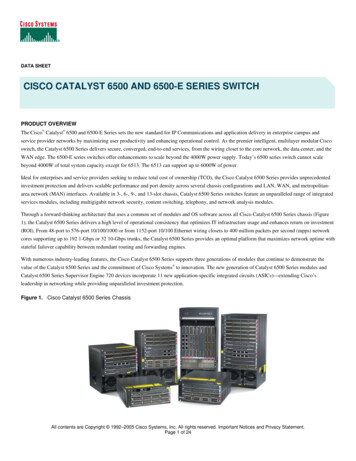
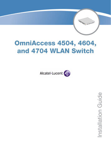
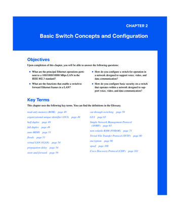
ITU G.652 and G.655 standards. The following table describes features of the G.652 and G.655- compliant fibers.Table 4: Features of G.652- and G.655-compliant fibersSingle-mode fiberWavelength (nm)FeaturesG.652-compliantApplications typeConnecting transceiverfiber (standard1260 to 1360Zero dispersion at 1310modules with a centralsingle-mode1530 to 1565nmwavelength of 1310 nm orfiber)1550 nm.G.655-compliantfiber (non-zerodispersion1530 to 1565Near-zero dispersionaround 1550 nmshifted fiber)For 1550 nm wavelengthdivision multiplexing (WDM)transmissions.Fiber diameterFiber diameter is expressed as core diameter/cladding diameter, in μm. For example, 9/125 μm means that thefiber core diameter is 9 μm and the fiber cladding diameter is 125 μm.For the HPE devices, the following fiber diameters are recommended: G.652 standard single-mode fiber: 9/125 μm G.655 non zero dispersion shifted single-mode fiber: 9/125 μm G.651 standard multimode fiber: 50/125 μm or 62.5/125 μmConnectorCover the connector with a dust cap when it is not connected to any optical fibers.Connectors connect transceiver modules to the corresponding transmission media. The transceiver modules availablefor Aruba products use the following types of connectors:Lucent connector or local connector (LC).Single LC connectors (also known as Simplex) are typically used for 1G & 10G BiDi (Bidirectional) optics. Dual LCconnectors (Duplex) are typically used in normal optical types.Note: 40G BiDi uses only Duplex fiber versus MPO (see below) for 40G SR4 applications.Figure 1: LC connector (a simplex connector is shown)Note: Multifiber Push On (MPO) connector.Router-Switch.com6
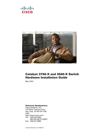
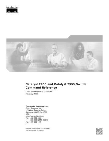
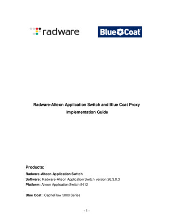
Figure 2: MPO connectorThe 40G QSFP MPO transceiver modules use only female MPO connectors, which have guide holes in the end face ofthe MPO connector (the transceiver has guide pins within the MPO receptacle).MPO connectors are classified as the following types based on the polish type: Physical contact (PC): End face polished flat. Angle-polished contact (APC): End face polished with an angle, typically 8 .MPO connectors are available with 12 fibers or 24 fibers:12-fiber MPO connector (40G, SR4, eSR4, and 100G SR4 transceivers use 8 of the available 12 fibers. The four center fibersare unused.)Figure 3: End face of a 12-fiber connector and channel assignmentMPO transceivers typically use four channels to communicate. These channels are assigned using the outer eightfibers (the center four are unused).Transmit channels are one set of four fibers, and the receive channels are on the other set of four fibers. Becauseof this, the cables used and fiber cable connections from endpoint to endpoint effectively create a crossoverconnection.Be aware that using two crossover cables in series cancels this effect and no connection will be established. An oddnumber of crossovers combined with straight-thru fiber connections will effect a crossover connection.The channel layout indicates that the left four fibers are Transmit, and must reach the opposite transceiver Receivechannels (and in proper channel order).Optical parametersThis guide provides average transmit and receive power ranges for transceiver modules.Transmit powerTransmit power is the power at which the transmitter of an optical transceiver module transmits optical signals, in dBm.Receive powerReceive power is the power at which the receiver of an optical transceiver module receives optical signals, in dBm.Router-Switch.com7
Use of attenuatorsTransceivers are designed to transmit light pulses at a power level that accounts for loss in the fiber optic cabling, andmeets the receiver input thresholds of the link partner optical transceiver.If you are using a fiber cable with less light loss than expected (for example, in a test environment and you do not have a40km spool of SMF available), use attenuators to affect the transmit level to within the receive sensitivity of the othertransceiver -- you will need to condition both fibers (sends in both directions). If you do not, you risk overdriving theReceive end and permanently damaging the transceiver. For example, a 40GER4 has a highest transmit level of 4.5dBm,but the Receive Sensitivity can be no higher than -4.5dBm. That means that there must be at least a 9dBm loss on thelight level to be within the standards (4.5 - (4.5) 9dBm required).Copper transceiver modulesCopper transceiver modules transmit signals over Category-5 unshielded twisted pair (UTP). UTP transmissioncover shorter distances than fiber transmission and can be used in small-sized networks only.Copper transceivers are supported in 1G SFP and 10G SFP ports where listed in the Support Matrix tables.Transmission distanceThrough UTP cables, signals can be transmitted over a distance of 100 m (328.08 ft.) only. This behavior occurs becausesignals attenuate during transmission through the UTP cables.Attenuation refers to the dissipation of the power of a transmitted signal as it travels over a cable. Attenuation occursbecause signal transmission suffers certain resistance from the cable, which weakens the signals as they travel over thecable. When signals are tr
for Aruba products use the following types of connectors: Lucent connector or local connector (L ). Single L connectors (also known as Simplex) are typically used for 1G & 10G iDi (idirectional) optics. Dual L connectors (Duplex) are typically used in normal optical types.