Transcription
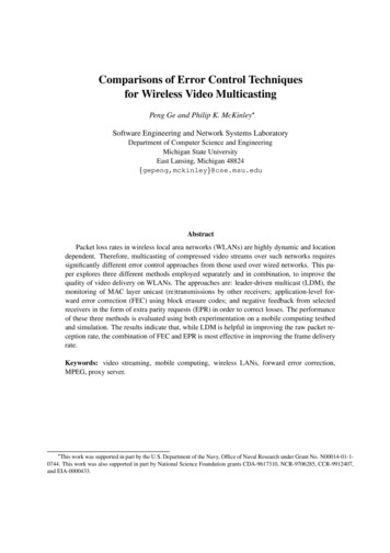
Comparisons of Error Control Techniquesfor Wireless Video MulticastingPeng Ge and Philip K. McKinleySoftware Engineering and Network Systems LaboratoryDepartment of Computer Science and EngineeringMichigan State UniversityEast Lansing, Michigan 48824gepeng,mckinley @cse.msu.edu AbstractPacket loss rates in wireless local area networks (WLANs) are highly dynamic and locationdependent. Therefore, multicasting of compressed video streams over such networks requiressignificantly different error control approaches from those used over wired networks. This paper explores three different methods employed separately and in combination, to improve thequality of video delivery on WLANs. The approaches are: leader-driven multicast (LDM), themonitoring of MAC layer unicast (re)transmissions by other receivers; application-level forward error correction (FEC) using block erasure codes; and negative feedback from selectedreceivers in the form of extra parity requests (EPR) in order to correct losses. The performanceof these three methods is evaluated using both experimentation on a mobile computing testbedand simulation. The results indicate that, while LDM is helpful in improving the raw packet reception rate, the combination of FEC and EPR is most effective in improving the frame deliveryrate.Keywords: video streaming, mobile computing, wireless LANs, forward error correction,MPEG, proxy server. This work was supported in part by the U.S. Department of the Navy, Office of Naval Research under Grant No. N00014-01-10744. This work was also supported in part by National Science Foundation grants CDA-9617310, NCR-9706285, CCR-9912407,and EIA-0000433.
1 IntroductionWith rapid advances in wireless packet networking technology, it is becoming possible to provide mobileusers not only with voice and data connections, but also with video communication services. Many emergingmobile applications involve the delivery of video streams to mobile hosts (MHs). Some, such as video-ondemand and video-clip browsing, deliver recorded video to users. Others, such as video conferencing,require real-time delivery of live interactive video streams. This paper focuses on the latter. In eithercase, wireless networks (including both wireless local area networks and third generation cellular networks)provide sufficient bandwidth to support compressed video transmission.One area that presents a unique set of problems is video multicast, in which multiple MHs receive thesame video stream from one sender. A wireless channel is usually characterized by bursty and locationdependent errors. Therefore, each MH is likely to lose some packets in the video stream, and different MHsare likely to lose different packets. A simple ARQ (Automatic Repeat reQuest) approach may be inadequateto error control, since the sender may experience ACK/NAK implosion [1] and the same packet may berequested multiple times by different receivers. In the worst case, the sender may have to transmit everypacket multiple times.The primary goal of this research is to discover which error control techniques are most effective toimprove quality-of-service (QoS) for real-time wireless video multicast, given external constraints such asbandwidth limitations and packet loss distributions. This study is part of the Pavilion project [2], whichaddresses object-oriented middleware support for collaborative applications such as computer-supportedcooperative work and computer-based instruction. One focus area of the Pavilion project is on supportingcollaborative applications in which some of the participants are connected via wireless local area networks(WLANs). Typical settings include schools, offices, factories, and hospitals. Many approaches to accommodating mobile users involve proxies [3, 4], which represent wireless nodes to the rest of the wired network.Figure 1 depicts the physical configuration of a Pavilion proxy that supports three mobile hosts on a wirelessLAN. In earlier papers, we have described the use of Pavilion proxies to support collaboration via wirelesshandheld computers [5], forward error correction on audio streams [6], and reliable multicasting of data [7].In this paper, we extend our earlier studies by exploring proxy services for multicast video streamstransmitted over WLANs. Three different approaches are studied, separately and in combination. The firstmethod, leader-driven multicast (LDM), is actually a MAC-layer enhancement in which network interface1
Figure 1. Proxy configuration on a wireless LAN.cards at receivers are able to monitor unicast transmissions to a designated group leader. The quality of thestream received by the leader is very high, due to unicast RTS/CTS signaling and MAC-level retransmissionsby the access point. Moreover, these retransmissions produce a residual effect and improve reception at otherreceivers. The second method is to have a proxy insert FEC information into the data stream. We use blockerasure codes [8], because of their ability to correct uncorrelated packet losses among different receivers. Inaddition, we apply the QoS-Directed Error Control (QDEC) approach proposed by Nahrstedt et al. [9], inwhich different rates of redundancy are applied to different types of frames (e.g., more for I and P frames,less for B frames in MPEG stream). The third method is to enable selected receivers, called responders, torequest additional parity packets in order to correct packet losses. We refer to this technique as Extra ParityRequest (EPR). Current 802.11 WLANs offer a high enough bit rate that the additional round-trip latencybetween responders and the proxy can be absorbed by a small playback delay at receivers.In a preliminary study [10], we explored the combination of FEC and EPR through experiments on asmall wireless testbed; we briefly summarize those results later in the paper. In the current study, we usesimulation to investigate scenarios and conditions beyond the scope of the testbed. The results indicate thatwhile LDM is helpful to improve the packet reception rate, the combination of FEC and EPR atop traditionalUDP/IP multicast is more effective in improving the frame delivery rate for up to 25 receivers in a singlewireless cell. The main contribution of this work is to identify which combinations of parameter settingsand other options are appropriate for various channel conditions.The remainder of the paper is organized as follows. Section 2 provides background information onseveral relevant topics. Section 3 describes the error control techniques that were evaluated, and Section 42
describes the architecture and operation of the proxy used in this study. Section 5 summarizes the resultsof an experimental performance study conducted on our testbed, while Section 6 presents the results of thesimulation study. Section 7 discusses several related works. In Section 8, we summarize the results anddraw the conclusions.2 Background InformationSeveral issues influence the design of video services in WLANs: bandwidth needs of video streaming,characteristics of WLANs, operation of error control codes, and potential benefits of using a proxy. Each ofthese is discussed in turn.Bandwidth requirements. One of the most important issues is the encoding format and, consequently,the bandwidth consumed by the video stream. In this work, we investigated the MPEG-1 video format [11].Our ongoing considers other formats, including the scalable encoding techniques employed in MPEG-4 [12].MPEG-1 includes three types of frames: I frames coded as still images, P frames predicted from the mostrecent I or P frame, and B frames predicted from the closest two surrounding I or P frames. The averagebandwidth required by a typical MPEG-1 video stream, with typical encoding settings, is approximately1Mbps. If audio is included, the bandwidth required is approximately 1.2Mbps. According to the MPEG-1standard, typical recommended encoding settings are 30 frames per second and a repeating 12-frame patternof IBBPBBPBBPBB. In the default source input format (SIF), each frame is 320x240 pixels in size; typicalframe sizes (in bits) are given in Table 1. While other video encoding methods such as H.263 and MPEG-4provide lower bit rates, our goal in this study was to investigate the issues in delivering full MPEG streamsacross wireless networks.Table 1. Typical MPEG-1 Frame Sizes (bits)Level30 Hz SIFI150,000P50,000B20,000Average38,000Wireless LAN characteristics. Four major characteristics of WLANs need to be considered in thedesign of a video multicasting service. First, early WLAN products offered only a maximum data rate of2Mbps with an effective maximum data rate of 1.6Mbps, which is barely enough for a single MPEG-1 streamwithout FEC parity packets. However, current WLAN products offer 11Mbps, with an effective maximum3
data rate of about 6Mbps, which is enough to carry 2 or 3 streams with error control. Moreover, 54MbpsIEEE 802.11a products, expected to be available soon, will be able to carry many MPEG-1 streams. Second,our prior experiments confirm that WLAN packet loss rates are highly dynamic and location-dependent [7];a short excursion outside our laboratory can quickly raise the packet loss rate to be above 50%. Third, the802.11 MAC layer provides link-level acknowledgements for unicast frames, but not for multicast frames.Figure 2 demonstrates the difference between unicast and multicast frame delivery rates for a typical locationnear our laboratory. As shown in Figure 2, applications observe a higher packet loss rate in multicastchannels than in unicast, due primarily to the lack of link layer acknowledgements. Fourth, since the wirelesschannel is a shared broadcast medium, it is important to minimize the amount of feedback from receivers.Simultaneous responses from multiple receivers can cause channel congestion and burden the access point,thereby hindering the forward transmission of video frames. To address this problem, we use global NAKsuppression (GNS) [13], which will be discussed later.Figure 2. Unicast and multicast packet loss traces.Block Erasure Codes. A technique commonly used to handle losses in real-time communication isforward error correction (FEC), whereby redundant information in the data stream enables the receiver tocorrect errors/losses without contacting the sender. Since CRC-based error detection at the link layer results in the removal of the corrupt packets, many FEC-based protocols target these “erasures”. Rizzo [8]studied the feasibility of software encoding/decoding for packet-level FEC, and implemented the FEC en- coder/decoder in C. As shown in Figure 3, an ( ) block erasure code convertsgroup ofcoded packets, such that anypackets [14]. Usually, the firstmaining of the source packets into aencoded packets can be used to reconstruct thepackets in each group are identical to the original sourcedata packets; the re-packets are referred to as parity packets. The advantage of using block erasure codes forwireless multicasting is that a single parity packet can be used to correct independent single-packet lossesamong different receivers.4
ENCODERDECODERFigure 3. Forward Error Correction.Proxy-Based Error Control. The FEC functionality is usually provided by a proxy node that residesbetween the sender and the receiver, as shown in Figure 1. This proxy can provide extra processing powerand extra buffering space at minimum cost. Since the main role of an FEC proxy is error control, placing theproxy as close as possible to the wireless MHs (e.g., within the same subnetwork) has two obvious benefits.First, the overhead for FEC packets is localized, so that bandwidth is not wasted on other links. Second,retransmissions are also localized. While the retransmissions of video stream packets traveling across theInternet may be impractical due to the high latency, a local proxy can respond quickly enough to meet thedeadlines of frame playback at the receiver.3 Error Control MethodsIn this section we describe the three approaches that we used in this investigation to improve the delivery ofMPEG-1 video streams in WLANs.3.1 Leader-Driven Multicast (LDM)The first error control method, LDM, requires a slight modification to the IEEE 802.11 MAC layer protocol. As mentioned earlier, 802.11 unicast is more reliable than 802.11 multicast, because unicast usesRTS/CTS/ACK signaling in the MAC layer and multicast does not. Since all wireless signals are broadcasted into the air, the idea of LDM is to implement multicast by enabling MHs to monitor unicast channels.Consider a group of WHs that join the same multicast session. Instead of sending a pure multicast packetstream to the group address, the Access Point (AP) sends a unicast stream to a leader WH, and other WHsin the session monitor this unicast channel.5
Clearly, LDM should significantly improve the reception rate of the leader, compared to raw multicast,due to the unicast signaling in MAC layer. Moreover, the reception rate at other receivers may also improve,if the MAC layer retransmissions for the leader happen to cover the packet losses of those nodes. However,it is difficult to tell how many packet losses can be corrected in this way, since the losses among differentreceivers are totally unrelated. However, in most situations the reception rate of each receiver should be atleast as high as when using pure multicast.Furthermore, LDM eliminates the need for pure multicast in the forward traffic stream. The advantageof this change can be seen in the following example. Assume we have two concurrent multicast sessionsin a single WLAN. By using pure multicast, each session has no knowledge of another session’s existence,and therefore, tries to utilize the channel at its own convenience. In the worst case, this behavior will causethe collision of many data packets for both sessions. On the other hand, by using LDM, each session hasto reserve the wireless channel with RTS/CTS signaling before it can send out a data packet, which shouldproduce more controlled channel access and, hence, fewer collisions.A potential drawback of this new multicast method is that a leader with poor reception might consumemore bandwidth than pure multicast, due to excessive RTS/CTS hand-shaking or data retransmissions. Inaddition, allowing a WH to monitor unicast traffic not targeted to itself may compromise the security ofWLANs. However, the same problem occurs in a wired LAN, where anyone connected to the network canaccess all the data packets.3.2 Forward Error Correction for VideoThe second method is to apply FEC to video streams. FEC codes such as Rizzo’s [8] are parameterizedbyand and need to initialize data structures and buffering space prior to invocation. As soon as packets arrive at the proxy, the code can be invoked to produce the dataparity packets. Of course, as ourprotocol accumulates the data packets for a given group, it also forwards those data packets to the receiver.The problem is that many video frames are small and do not require packets. Allowing an FEC group tospan two (or more) frames would cause undue delay in delivery and decoding of the first frame, and wouldrisk missing playback deadlines.To solve this problem, we use dummy packets, which were introduced for Pavilion’s wireless reliablemulticast protocol [7]. In this approach, we invoke the FEC code using the data packets in the frame, plusan appropriate number of packets that are initialized to all 0’s. These dummy packets are used only for6
computing the parity packets, and are not actually sent out into the channel. The application level headerof each packet contains information on the FEC parameters, frame size, and the number of dummy packets,enabling the receiver to decode the packets correctly.As an example, consider the use of a (12,8) FEC code, and assume that a given frame comprises 5 datapackets. The FEC code is invoked with the 5 data packets and 3 dummy packets, producing 4 parity packets,which are transmitted following the 5 data packets. As long as a MH receives 5 out of the 9 packets, thereceiver can reconstruct the frame by using 3 of its own dummy packets.In addition to dummy packets, we also make use of QoS-directed error control (QDEC), a techniqueproposed by Nahrstedt et al. [9] for video multicast in wireless networks. Those authors argued that compressed video formats, such as MPEG, usually involve encoded frames of varying importance, and therefore,error control should be performed in a differentiated manner. In the case of an MPEG-1 video, for example, QDEC applies FEC to I frames and P frames, while providing no redundancy for B frames. Since Iand P frames are more important than B frames in the MPEG stream, this approach provides a good tradeoff between QoS and the bandwidth consumed in WLANs. Specific QDEC parameter settings are discussedlater.3.3 Extra Parity Request (EPR)The third method, EPR, involves feedback from selected receivers to the proxy. For each FEC group, theproxy computes parity packets. In order to save the bandwidth, however, it may choose to send initiallyonly a subset of these parity packets, with additional parity packets sent only upon request from MHs thatreceive fewer than packets in the group. This technique was used in Pavilion’s reliable multicast protocol,for example.In the case of video streams, however, whether or not an MH should be allowed to request extra paritypackets depends on whether those additional packets can be received without missing the playback deadlineof that frame. For first generation wireless LANs, meeting this deadline is difficult, at least for large frames.Considering Table 1, the average length of I frames is 150Kbits. At 1.6Mbps (the maximum effective bandwidth of our 2Mbps WaveLAN network), such a frame requires approximately 94ms to be transmitted,implying that delivery of the stream must already be delayed by at least 2-3 frame times. Requesting extraparity packets and waiting for their arrival may create an unacceptable playback delay. On an 11Mbps network with a 6Mbps effective bandwidth, however, such a frame requires only 25 ms to be transmitted. By7
inserting a relatively small delay (100ms or so) in playing back the video stream at the MH, such “backward” error control can easily be absorbed without significantly affecting the video quality. We refer to thistechnique as Extra Parity Request (EPR).If EPR is enabled, then the issue of NAK suppression arises. Specifically, as the number of MHs increases, we risk NAK implosion at the proxy. To address this problem, we use global NAK suppression [13].Instead of unicasting NAKs to the proxy alone, the receiver multicasts the NAK, so that it is heard by allMHs within range. A simple timer at each MH is used to introduce a small random delay for each NAK. Ifanother MH hears the NAK and determines that its own pending NAK is subsumed, then it cancels its NAK.Similarly, for a given FEC group and a given time window, the proxy responds only to the NAK requestingthe most packets.4 System Architecture and OperationWhile this paper focuses on simulation results (Section 6), those simulations are grounded in a prototype implementation that we constructed on a small wireless testbed. This section describes the system architecture,and Section 5 discusses sample experimental results.Figure 4 shows the main components of our system. The sender delivers the video stream to the proxyvia the wired network. Currently, the sender reads a recorded video file and sends it out at the rate of 30frames per second, instead of sending out the video captured by a video camera. In this way, we are able tocompare the results of different experimental runs, using the same video stream. This sender component ofthe system can later be replaced with a camera and a real-time MPEG encoder.Video ProxySender30 fpsReceiverto playerReceiveProxyControlAssemblyRepackageFEC DecodeFEC EncodeMulticastFeedbackMonitorLoss Rate30 fpsFigure 4. System architecture.8Receive
The proxy receives the video stream in the unit of frames, organizes each frame into a set of smallerpackets, divides the packets into FEC groups, computes a set of parity packets for each group, and multicaststhe data packets and a number of proactive parity packets on the wireless network. The FEC componentof our video proxy uses public domain implementations coded by Rizzo [8]. Using a simple GUI at eachreceiver, the proxy can be configured dynamically to apply different error control services for different typesof frames, to change the FEC parameters, and to support extra parity requests from receivers.As the receiver collects packets for a given FEC group, the data packets can be reconstructed by theFEC decoder when the number of packets received is greater than the number of original data packets in thegroup. If the number of packets received for a given group is not sufficient to recover from the losses, theneither a partial frame is delivered, or a request for additional parity packets is sent to the proxy. Upon receiptof such a request, the proxy should multicast extra parity packets from the same FEC group. If enough ofthese packets arrive at the receiver before a playback timer expires, then the group can be fully reconstructedand delivered to the player.5 Experimental EvaluationIn this section, we provide a sample of the experimental results from which our simulation study was derived.Our mobile computing testbed currently includes conventional workstations connected by a 100Mbps FastEthernet switch, three WLANs (Lucent WaveLAN, Proxim RangeLAN2, and Cisco Aironet), and severalmobile handheld and laptop computer systems. All tests reported here were conducted on the Aironetnetwork, which uses direct sequence spread spectrum (DSSS) signaling and has a raw bit rate of 11Mbps.The physical configuration of the test environment is depicted in Figure 5. The Aironet access point and thewired participating stations were located in our laboratory. The sender and the video proxy were executedon two desktop workstations with 450 MHz dual processors, and the mobile nodes were 300 MHz laptopsequipped with Aironet network interface cards.In our experiments, we varied the location of the mobile nodes with respect to the access point. Thewalls in our building are constructed of concrete blocks, dramatically affecting packet loss rates for wirelesslaptops. Location 1 is inside our laboratory. Location 2 is outside the laboratory and approximately 10meters down a corridor. Location 3 is inside an instructional laboratory approximately 20 meters down thesame corridor. For each location, the MHs continuously receive five minutes of video stream and record the9
Figure 5. Experimental configuration.number of frames that arrive (a) without any error control, (b) using only FEC, and (c) using a combinationof FEC and EPR. Even if enough parity packets to reconstruct a frame eventually arrive at a receiver, theframe is considered lost if it cannot be reconstructed before its playback deadline.We varied the values of and , depending on the size of the frame. The ( , ) codes that we used are(10,4), (20,8), and (30,12). The proxy applies a fixed pro-active FEC rate of 30% to I frames (that is, if thenumber of data packets is , then the number of parity packets sent pro-actively for that group is )and a 20% rate to both P and B frames. Additional parity packets can be requested for any type of frame.When the video starts to arrive at the receiver, its playing is delayed by 100-200 milliseconds in order toabsorb the delay in requesting and sending additional parity packets. We consider this delay acceptable forinteractive video streaming. Moreover, since IEEE 802.11a wireless products with maximum data rate of 54Mbps are expected to be available soon, it will be possible to reduce this start-up delay considerably, whilestill enabling retransmissions from the proxy.Figure 6(a) shows a trace from one of the receivers in location 1. The most interesting point concerningthis trace is the raw loss rate. With our older 2Mbps WaveLAN network, we observed that receivers withinour laboratory rarely lost packets. The faster network is apparently much more sensitive to noise, andwithout link-level retransmissions, multicast traffic experiences up to 10% loss. As shown, FEC aloneimproves the delivery rate only slightly. However, the combination of FEC and EPR produces a deliveryrate near 100%.10
Location 180%60%40%20%FEC NAKsFEC OnlyNo Error Control80%60%40%20%FEC NAKsFEC OnlyNo Error %5Location 2100%Percentage of Frames DeliveredPercentage of Frames Delivered100%Time (sec)Time (sec)(a) location 1(b) location 2Location 3Percentage of Frames Delivered100%80%60%40%20%FEC NAKsFEC OnlyNo Error 6550520350%Time (sec)(c) location 3Figure 6. Frame delivery rates at three locations.Figures 6(b) and (c), respectively, show the results for locations 2 and 3. Despite the increased lossrate at location 2 compared to location 1, the combination of FEC and EPR produces the delivery rate closeto 100%. For location 3, near the cell periphery, even these combined approaches cannot deliver a perfectvideo stream. However, considering that the loss rate is over 50% for several seconds, the error controlmethods improve the delivery rate considerably. In the worst 5-second interval, over 70% of the packets arelost without error control, but nearly half of these are recovered by FEC and EPR. Moreover, we note thatwhen the video is played, even these periods of significant loss translate into relatively minor glitches in thevideo stream.Figure 7 shows samples of the effects of different approaches to error control on the quality of framesfrom a particular action sequence involving a helicopter. For the top two frames, the three approaches exhibit11
relatively small differences in quality. For the bottom two frames, however, the improvement due to EPR isobvious.(a) no error control(b) FECQDEC(c) FECQDECEPRFigure 7. Example differences in frame quality with various error control strategies.6 Simulation ResultsIn this section, we present the results of our simulation study. Due to space limitations, we focus on thoseresults that are most significant; additional results can be found in [15].12
6.1 Simulation EnvironmentWe conducted our simulation study using MX, a simulation tool that we are developing as part of anotherproject [16]. Unlike other simulation programs, such as ns-2, MX enables unmodified application programsto be executed atop a simulated network. In MX, a file written in a configuration description language describes the characteristics of the network components: host computers, routers, operating system delays,network interface card properties, and so on. The file also describes the mapping between program components and the simulated hosts (virtual nodes). A socket-level API enables unmodified application code tobe linked with the simulator; both Java and C interfaces are currently supported. Protocol modules in avirtual node are implemented as objects with uniform interfaces; multiple modules can be linked togetherto form a protocol stack. Supported protocol modules include TCP, UDP, IP, CSMA/CD, MACA, and IEEE802.11, and this set can be easily expanded. Both correlated and uncorrelated error behavior can be modeledon physical channels. Details of the MX simulator can be found in [17].The video stream we use for the simulation is the same one that we used in the experiments. ThisMPEG-1 stream has 413 frames in 13.8 seconds. The total length is 1.33MB, which makes the averagebandwidth consumed around 812Kbps. I and P frames are usually larger than B frames, so that B framehave better chance to be delivered than I and P frames, either by pure multicast (PM) or by leader-drivenmulticast (LDM)We conducted simulations using two different channel characteristics. The first (Channel 1) has a biterror rate of 0.00125%. The second (Channel 2) has a bit error rate of 0.00375%. We also simulate both1100- and 500-byte packet streams. The simulated topology is the same as our experimental environment,except that we increase the number of receivers.6.2 No FECIn the first group of our simulation tests, we transmit only the plain video stream, enabling us to assessthe effects of LDM versus PM. We vary the value of packet size as well as the wireless channel quality toproduce different runs. Figure 8 shows that the leader in LDM usually receives nearly all of the frames, asexpected. The other receivers in LDM suffer more packet losses than the leader, but they are usually betterthan any receiver in PM. This is the result we expected: LDM can provide significant improvement for the13
leader, and the reception rate at the other receivers also improves due to the residual effect of MAC-levelretransmissions to the leader.(a) Channel 1, 1100-byte packets(b) Channel 2, 1100-byte packets(c) Channel 1, 500-byte packets(d) Channel 2, 500-byte packetsFigure 8. LDM vs. PM for plain video stream.The B frames have higher delivery rate than I and P frames have, because B frames are usually smallerthan I and P frames, which gives B frames a better chance to be delivered in full. Moreover, when the channelquality is worse (eg., Channel 2 vs. Channel 1), the receivers other than the leader in LDM experience moreimprovement over PM, because they are more likely to receive useful retransmissions due to the leader’sincreasing packet losses.6.3 Using FEC without EPRIn the second group of the tests, we apply FEC to the video stream and compare the performance of LDMand PM. The FEC rate is 60-40-20% for I-P-B frames, respectively. Figure 9(a,b) shows the result of videostreaming when the pa
dating mobile users involve proxies [3,4], which represent wireless nodes to the rest of the wired network. Figure 1 depicts the physical configuration of a Pavilion proxy that supports three mobile hosts on a wireless LAN. In earlier papers, we have described the use of Pavilion proxies to support collaboration via wireless