Transcription
Atlas Copco Portable Air CompressorXAS 185 JD7Parts list1310 3011 74 Ed. 0 2007-02“Copyright 2007, Atlas Copco Compressors LLC Westfield, MassachusettsAny unauthorized use or copying of the contents or any part of this book isprohibited. This applies in particular to trademarks, model denominations, partnumbers and drawings.”No. 1310 3011 74 Ed. 02007-02
OWNERSHIP DATAUnit model:Owner's machine no.:Electric motor type:Unit service no.:Delivery date:Motor serial no.:Service plan:First start-up date:Selected LubricantsCompressor:Capacity:Bearing grease type, electric motor:Printed Matter Nos.Atlas Copco instruction book:Atlas Copco logbook:Atlas Copco parts list:Motor parts list:Local Atlas Copco RepresentativeName:Address:Telephone:Contact persons:Telefax:Parts:Example parts listRef. Part numberQty Name123158 Screw - Round Head2Hinge2Fender1310 0332 641310 0326 911310 0326 79Service:RemarksExplanation of columns:Ref. - Reference number. Relates a part in list and drawing. "x" means that the part is not shown on the drawing. "-"indicates the beginning of a new list item.Part number. "---" directs to consult another list of which the heading mostly has the same designation . "***" meansthat the part is not available as spare part. Parts followed by one dot are comprised in the assembly(ies) listed abovethe first dot.Qty - A number indicating the quantity of parts. The quantity is only related to its corresponding reference number("Ref") and may differ from the total quantity of this part for the entire unit. For parts of an assembly the quantitymentioned is for one assembly. "AR" means "as required" : bulk material or quantity to be determined.Name - Mostly part names. When machine types, Classification Societies, dimensions, etc. are mentioned under thesame "Designation", look carefully for the part number for your specific equipment. When a selection is to be made,the various selections are indented and preceded by a dash.Remarks - A number followed by a bracket, e.g. 1), refers to a footnote.A number in bold, e.g. 1, refers to a "Service Kit". For the "Service Kit" number, see below list. Parts of one "ServiceKit" may be spread over several pages.ORDERING PARTSAlways quote the part number, "Designation" and quantity of the desired parts as well as type designation and serialnumber of the unit.21310 3011 74
Table of Contents1.Compressor Drive Group.52.Engine Mounts .73.Air Intake.94.Exhaust System .115.Cooling System.136.Air Outlet.157.Oil System .178.Regulating System .199.Fuel System.2110.Hood Assembly Steel Version.2311.Body Work Steel Version .2512.Hood Assembly Steel Version.2713.Bodywork PE Version 2914.Control Panel.3115.Electrical System .3316.Road Lighting.3517.Drawbar, Axle Assembly.3718.Decal Location .3919.Air Receiver .4120.Unloader Valve .4321.Actuating Valve Assembly.4522.Air Receiver Service Kit .4723.Unloader Valve Service Kit .4924.Speed Regulator Service Kit.5125.Maintenance Kits .531310 3011 743
16198191511108131714101265918237184202141310 3011 74
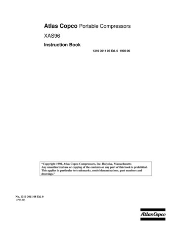
1. Compressor Drive GroupRefPart numberQty12345678910111213141516171819200211 1404 000300 0274 921604 0745 000337 5196 001604 0774 001615 5441 000147 1962 711310 0301 390147 1382 030108 1392 000147 1457 03SCRO 09180333 3227 000108 3417 001604 0761 000102 0460 000291 1113 001615 9398 010147 1420 031616 7194 8044111113121662113121NameRemarksCap screwWasherBushingParallel keyCoupling (male)WasherHex head screwBolt m14 x 160Bolt m10 x 140Spring pinBolt m14 x 140Cap screw .312" x 1.0lLockwasherSpring pinCoupling (female)Parallel pinLocknutHousingBolt m12 x 140Element O.I.S. K-381310 9045 00 Rev. 001310 3011 745
131112151452163107478481561310 3011 74
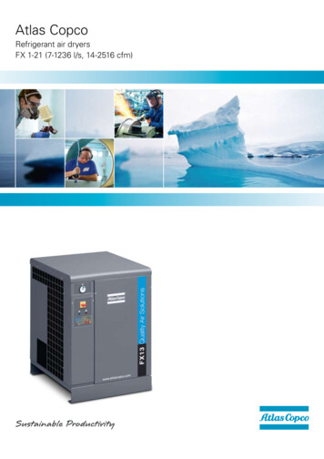
2. Frame and MountsRefPart numberQty1234567891011121314151310 0304 111310 4254 000147 1476 031310 0302 950291 1111 001202 8719 001202 9006 020147 1360 031310 4252 001619 2766 001604 4099 310301 2358 000147 1402 151604 4220 001310 4102 00124442481413341NameRemarksEngine - DieselMount - EngineScrew - M16 x 35StudLocknut - M10DiskVibration mountScrew - M10 x 20SupportScrewLifting HookWasherScrewLimiting DiscFrame1310 9045 01 Rev. 001310 3011 747
9123111713861910207185746155141612455481310 3011 74
3. Air IntakeRefPart numberQtyName12345678910111213141516171819201310 0301 581310 4152 001310 0301 660147 1323 030301 2335 001310 0345 211310 0323 831310 0301 551310 0301 591310 4153 001310 0341 730347 6131 000347 6119 001615 7667 820211 1325 000663 2106 160347 6113 001310 4256 000147 1475 030301 2378 00111662411113111412111Air Cleaner -EngineSupportDuctScrewWasherHoseClampHoseAir Cleaner - CompressorSupportHump HoseClamp M77Clamp M110Unloading ValveScrewO-RingHose ClampPipe Air 39261310030309Remarks1), 2)3), 4)Element-Engine Air FilterElement-Engine Safety Cartridge (optional)Element-Compressor Air FilterElement-Compressor Safety Cartridge (optional)1310 9045 02 Rev. 001310 3011 749
79621364534.101310 3011 74
4. Exhaust SystemRef123456789Part number QtyName1310 4150 001310 0301 621310 0345 551310 0339 541310 4151 001615 5664 001310 4264 001310 1477 001310 4163 00Exhaust PipeClamp - "V" BandClamp - Exhaust "2.25"Hose - Flex MetalExhaust PipeScrewMuffler - ExhaustClamp - Exhaust "2.25"Heat Shield112118111Remarks1310 9045 03 Rev. 001310 3011 7411
2523212222211211924222123 22102010141231041018262101013121310 3011 74
5. Cooling 26Part numberQtyNameRemarks1310 4237 001310 4239 000211 1251 000301 2321 001310 0342 831615 7690 001615 5664 001310 0342 811310 4249 000347 6113 000147 1247 031619 2766 001310 4261 001310 4281 001615 5664 000147 1363 030301 2344 001310 0342 891310 0352 021310 4270 001310 0304 171310 0323 841310 0311 971310 0304 191310 4234 001310 4235 0011661141164161144412234AR111Radiator/Oil CoolerFan SpacerScrewWasherFan GuardRing ClampScrewFanTop TankHose ClampScrewScrewLower Radiator Hose AssemblyUpper Radiator PipeScrewScrewWasherHose ClampHose ClampHose SleeveElbowHose ClampHoseAdapterPanelFan Box1310 9045 04Rev. 001310 3011 7413
0 3011 74
6. Air OutletRefPart 1604 9951 800663 3131 001604 7943 010663 3131 000333 3227 000147 1323 030571 0035 741310 4242 000663 7137 000663 7141 001604 3980 810653 1062 000686 3716 010211 1364 000301 2344 000211 1373 009125 6295 001619 2766 001310 1365 009747 6020 001310 0302 659710 5691 001615 5080 000661 1000 291310 0301 921111221111111341142211111NameRemarksTwin Ball ValveO-RingRestrictorO-RingLockwasherHexagon BoltNippleHoseO-RingO-RingOutlet ManifoldFlat GasketPlugBolt M10WasherBolt M10GasketScrewClaw CouplingRubber or Assembly1310 9045 05 Rev. 001310 3011 7415
11121112134131112871012111211SEE DETAIL A121156DETAIL A161310 3011 74
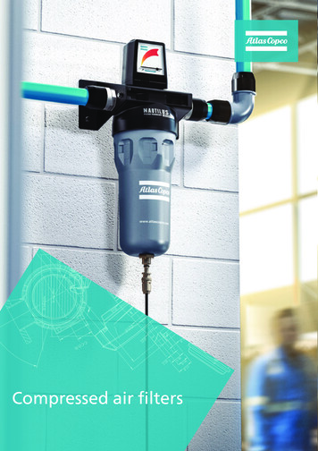
7. Oil SystemRefPart numberQtyName12345678910111213140300 8019 001615 7767 021619 3770 001613 6105 001202 8660 000661 1000 270147 1323 030147 1329 031310 4167 000301 2335 000072 8403 161202 8663 011310 0342 890346 1012 4421111132145m621Washer-flatHousing-oil filterNipple-hexFilter-oilNippleSeal amp-hoseClampRemarks1310 9045 06 Rev. 001310 3011 7417
222161723181718 2118201817241818251926181310 3011 74
8. Regulating SystemRefPart 242526272829300147 1322 030301 2335 000291 1110 001310 0369 571310 0316 530291 1108 001310 0302 459710 5906 000147 1329 091310 0302 460147 1250 030291 1110 001310 0301 610324 1130 00NUT 008461604 0321 800581 0000 381310 0345 790686 4201 030581 0000 470581 0000 330070 6002 050070 6002 040661 1020 000581 0000 521310 0304 131310 0316 520301 2321 001310 0369 561310 0353 evisThreaded RodNutLever ArmScrew-Self etCouplingHose AssemblyBall Socket, w/ DisconnectWasher-FlatCotter PinClevis PinRemarks1310 9044 57 Rev. 001310 3011 7419
07869201310 3011 74
9. Fuel SystemRefPart numberQtyName1234567891011121314151617181920211310 0315 801310 0311 981310 0302 291310 0323 840291 1110 000147 1323 030301 2335 001310 4276 001310 4277 001310 4275 001310 4278 001310 0349 921310 0349 941310 0343 631310 4259 001310 4257 001310 4258 001310 0343 881310 0327 021310 0317 971310 4149 etElbow - HoseCapTubeSender - Fuel LevelSwitch - Low Liquid LevelScrew - 10-24 x 0.5 Lg.GasketGauge - Fuel levelFueltankRemarks1310 9045 08 Rev. 001310 3011 7421
14151719, 29, 21, 232226152531311724111262415427289107185221310 3011 74
10. Hood AssemblyRef NotePart 242526271310 4114 211310 4240 001310 0327 781310 0357 171310 4124 001310 4122 001202 8673 000333 2121 000147 1246 030266 2108 001604 4317 001604 4056 001604 4062 001604 4057 001310 0327 870690 1132 000690 1140 001619 2665 001310 4125 801310 4125 001613 6650 010129 3172 011604 4317 0016041869 000333 2121 000266 2108 001604 6733 001221211222AR2111221AR111412222Hood AssemblyLabelBall StudLabelFoam InsulationFoam orProtectorRivetLabelLabelSealAccess Door *Remarks1310 9054 16 Rev. 001) Standard color is yellow ooFor availability of other colors consult an Atlas Copco sales representative.* Contained in the assembly.1310 3011 7423
32241310 3011 74
11. Body Work Steel UnitsRefPart 24252627282930313233341310 4103 291310 4103 001310 4104 001604 3423 001310 4108 001310 4109 291310 4109 001310 4110 001310 4144 001310 4112 291310 4112 001310 4113 001310 4126 291310 4126 001310 4127 001310 4243 001310 4262 001604 6686 001310 0327 871615 5664 001619 2766 001604 3858 000292 1305 001310 0327 781605 0025 001310 4148 001619 2766 0001471329 0302911110 0003012335 001310 4253 001615 5664 001619 2665 001310 0455 001619 2766 001310 4163 001619 2766 001310 4268 001112311121111111226288822221022218412121Front Baffle AssemblyBaffleFoam InsulationScrewFoam InsulationRear Baffle AssemblyRear BaffleFoam InsulationFoam InsulationSide Panel AssemblyPanelFoam InsulationSide Panel AssemblySide PanelFoam InsualtionBumperGas StrutLatchRivetScrewScrewPlugLocknutBall StudHinge ScrewHeat ShieldScrewGuardRemarks1****1***1**1**1310 9054 09 Rev. 001) Standard color is greyooFor availability of other colors consult an Atlas Copco sales representative.* Contained in the assembly.1310 3011 7425
314267810109853261310 3011 74
12. Hood Assembly PE VersionRefPart numberQtyName123456789101310 4222 001310 4161 001310 4162 001310 4160 001310 4168 001310 4159 001310 4158 0001471246 031615 5664 000301 2321 00111112112712HoodFoam InsulationFoam InsulationFoam InsulationFoam ****1310 9045 18 Rev. 001) Standard color is greyo2) Standard color is yellowooFor availability of other colors consult an Atlas Copco sales representative.* Contained in the assembly.1310 3011 7427
202827293033910 3267282627162221181514191211123251324534281310 3011 74
13. Body Work PE UnitsRefPart 23242526272829303132333435363738394041421310 4157 291310 4157 001310 4104 001310 4108 001615 5664 001310 4222 801310 4222 001310 4273 001310 4161 001310 4162 001310 4160 001310 4168 001310 4159 001310 4158 001619 2766 001615 5664 001310 4223 801310 4223 001310 4266 001310 4273 001615 5664 001310 4224 001615 5664 0001471328 030300 8019 001310 4225 001615 5664 000147 1328 030300 8019 001310 4226 001310 4147 001619 2766 001604 6457 001310 0327 781605 0025 001604 6276 0003012321 0001471244 031604 6275 001604 1869 001310 0369 540690 1132 001310 4240 t Baffle AssemblyBaffleFoam InsulationFoam InsualationScrewHood AssemblyHoodFoam InsulationFoam InsulationFoam InsulationFoam InsulationFoam InsulationBracketHingeScrewScrewRear Baffle AssemblyRear BaffleFoam InsualtionFoam ewScrewWasherCoverOutlet Valve BracketScrewGas StrutBall StudHinge PinLatchWasherScrewCatchBumperLabel – InternetLabel - LogoLabel – Model DesignationRemarks1***2**********1***1111310 9045 17 Rev. 001) Standard color is greyo2) Standard color is yellowooFor availability of other colors consult an Atlas Copco sales representative.* Contained in the assembly.1310 3011 7429
310 3011 74
14. Control Part numberQty1310 4263 801310 4265 001604 4017 001604 4028 001202 6584 001604 4039 011604 4068 001089 0312 111089 0608 041089 0608 031089 0341 011089 9206 310301 2321 000226 0305 420147 1249 030301 2318 000261 2107 000686 9252 691091 0168 000584 2310 010584 0080 090663 9095 001310 4263 001089 9420 011310 0317 971089 9326 0111111112114144444121111111NameRemarksControl Panel AssemblyLabelPressure GaugeCoverSealCoverWire HarnessLampholderButtonSwitchRelayCircuit BreakerWasherNutBoltWasherNutPlugBulbCompression NutConnectorO-ringControl Panel bracketHourmeterFuel GaugePushbutton1310 9045 11 Rev. 001310 3011 7431
17261016232832628242621221752062328141394153211310 3011 74
15. Electrical SystemRefPart 24252627281310 0311 651310 0311 671310 0311 669710 5899 011310 0310 891310 4247 001310 0333 251310 0345 461615 7831 021310 0350 590333 2243 001310 0330 411310 4244 000653 1124 000333 2225 000268 3205 000147 1320 031310 0363 910333 2243 000147 1476 031088 1301 020301 2321 000147 1249 031089 0585 011615 5664 000147 1323 030301 2335 001310 0365 lamp-batteryBoltBatteryCable-battery ( )Cable-battery (-)StrapOil Temperature SwitchCoolant Temperature SwitchWasher-springOil Pressure ockwasherScrewWire 10 9045 12 Rev 01310 3011 7433
24416728434134871310 3011 74
16. Road LightingRef12345678910Part number1310 4142 001310 4143 001310 0369 711310 4155 001088 1301 031310 4164 001310 4166 001310 0369 581310 0302 471310 0302 93Qty2214612822NameRemarksRed ReflectorYellow ReflectorLicense Plate LampGrommetWire TieWire HarnessRear Tail Lights – PE Version OnlyScrewRear Tail Lights – Steel Version OnlyGrommet for Rear Tail Lights – Steel Version Only1310 9045 13 Rev. 001310 3011 7435
6361310 3011 74
17. Drawbar, Axle AssemblyRef NotePart 242526271310 0303 941310 0314 511310 030 840147 1401 030301 2358 001310 0303 911310 4135 001310 0341 071310 0302 151310 0302 161310 0302 171310 0224 001310 0340 931310 0343 871310 0341 081310 0302 181310 4223 000144 4000 170292 1310 001310 0359 96SCR013421310 0303 831310 0400 091310 0400 111310 0340 121310 0342 110144 3461 032181010412242422101012421414112Wheel-tire assemblyLunette EyeWasherScrewWasher-flatScrewAxle AssemblyCotter PinGrease SealBearing ConeHubBearing CupSpindle NutGrease Dust CapLug NutStudDrawbar AssemblyScrew - 5/8-11 x 4.5" LLock NutChain AssemblyScrew - 3/8-16 x 3.75" LNutBracketBracketJackstand2" Ball HitchScrew*************RemarksOptional1310 9045 14 Rev. 00* Included in assembly.1310 3011 7437
1(2) the use of the compressor after such device orelement of design has been removed or renderedinoperative by any person.WARNING!!MAINTENANCE INSTRUCTIONSTampering with noise control system prohibited.Federal law prohibits the following acts or the causing thereof:(1) The removal or rendering inoperative by any persons,other than for purposes of maintenance repair orreplacement of any device or element of designincorporated into any new compressor for thepurpose of noise control prior to its sale or delivery tothe ultimate purchaser or while it is in userWEEKLY MAINTENANCE:CRACK OPEN OUTLET VALVES BEFORESTARTING!1. Service the air filter elements.Among those acts included in the prohibition against tampering are the acts listed below:2. Removal of any of the following1. Removal or rendering inoperative any of thea. sound absorptive material, includingfollowing:a. engine exhaust mufflersealing strips on doors, panels andother canopy partsb. cooling air exhaust and intake silencersb. fan shroudc. acoustic bafflesd. housing components, canopy or bottom3. Operation of the compressor with anypanelof the enclosure doors open.e. engine or compressor mountsf. inlet air throttling systemAtlas Copco Airpower 1613 3385 002. Check the:- Regulating system- Fuel system for fuel and oil leaks- Pressure of tiresANTES DE COMENZAR, ABRIR SOLO UNPOCO LAS VÁLVULAS DE SALIDA!3. Lubricate the ball joint and pivots of the speed regulator.4. Keep the unit clean.1310 4156 30GENERAL:1. For full operating and complete maintenance instructions, safety precautions, as well as forlocation of components, consult instruction book.2. Record all data, maintenance work effected, etc. in an operator's log book.3. During operation, doors may be opened for a short period only.1310 4156 20Compressor noise emission control informationThis compressor conforms to U.S. E.P.A. regulations for noiseemissions applicable to portable air compressors.The following acts or the causing thereof by any person are prohibited by the Noise Control Act of 1972:(A) The removal or rendering inoperative, other that forthe purpose of maintenance, repair, or replacement,of any noise control device or element of design(listed in this owner's manual) incorporated into thiscompressor in compliance with the Noise Control Act.(B) The use of the compressor after such device orelement of design has been removed or renderedinoperative.Atlas Copco Airpower 1613 3384 00GENUINE PARTSOPERATING INSTRUCTIONSBEFORE STARTING:DURING OPERATION:1. Check engine and compressor oil levels.2. Check fuel level.3. Drain water and sediment from fuel filter. (If necessary)4. Check air filter vacuum indicators. Service filter element if indicator shows red.5. Check to make sure Circuit Breaker is not tripped. (Circuit Breaker is located inside canopy driectlybehind control panel)At regular intervals check:1. Vacuum indicators. If red part shows full out,stop unit and service filter element.2. Unloading and working pressures.N OTE: Maximum out-of-level operation is 15 .STARTING:STOPPING:1. Crack open the air outlet valve(s).2. The starter switch has four positions - "OFF" -"RUN" - "AUX" and "START". Turn switch to "START"position to engage the engine starter and then release to "RUN" position when fault lights go out. If theengine fails to start, return the start switch to the "OFF" position. Allow any built up air pressure to bleedoff for at least 20 seconds before another restart is attempted.Failure to allow proper bleed down ofair pressure may result in damage to the engine's starter.1. Close air outlet valve(s) and allow engine toidle for two minutes.2. Move starter switch to "OFF".3. Fill fuel tank at the end of each days operation.TIRE AND LOADING INFORMATIONThe weight of cargo should not exceed 178 kg or 391 lbs.SERVICE PAKS1310 3003 741310 3003 751310 3003 73normal (250/750 hr)yearly (500hr)yearly (1000hr)COMPRESSOR OIL1615 5947 001310 0334 301.3 - Gallon (5 Liter) container5 - Gallon pailENGINE OIL1615 5953 001615 5954 001.3 - Gallon (5 Liter) container5.2 - Gallon (20 Liter) pailTIRESIZECOLD TIRE PRESSUREFRONT205/75 D1550 PSI/350 kPaREARSPARESEE OWNER'SMANUAL FORADDITIONALINFORMATION1310 0303 691310 0302 74CIRCUIT BREAKER RESETN OTE: For cold temperature operation use engine pre-heat. To operate pre-heat, turn unit to "ON"position and depress push button for 30 seconds, then turn switch to start position.1310 0302 753. Allow engine to warm up before closing the air outlet valves.WARNING1310 4156 10CALIFORNIAL PROPOSTION65 WARNINGdieselDiesel engine exhaust and someof its constituents are known tothe State of California to causecancer, birth defects, and otherreproductive harm.1310 3112 36TIE DOWNHEREWARNINGFIRE HAZARD!Do not use ether to aid instarting. Unit is equipped withglow plugs.1310 0354 951310 0302 83WARNINGEngine is fitted with an alternator.Failure to comply with the following could result indeath or serious injury1. Never reverse the battery polarity.2. Never disconnect the battery while the engine isrunning. When starting with a spare battery,connect this battery in parallel with the standardone. Disconnect the spare battery after startingwithout disconnecting the standard battery.3. Never run the engine with the main or voltagesensing cables disconnected.1310 0302 734. Disconnect the alternator and regulatorconnections during arc welding on the unit .CAUTIONDANGERDANGERDo not mix oil brands.Follow Atlas Copco operatinginstructions for proper maintenance,lubricant grades and changeintervals.Use only selected lubricantspecified by Atlas Copco.Failure to comply will void warrantyand may result in equipmentdamage.1310 3112 52BURST HAZARD!INHALATIONHAZARD!Relieve air pressure beforeloosening oil filler cap or anyfittings.9747 6014 00Contents under pressure.Failure to comply will resultin death or serious injury.Do not use discharged airfor breathing.Failure to comply will resultin death or serious injury.9747 6011 002CAUTIONBURN HAZARD!Keep clear.Hot exhaust may burn.Failure to comply mayresult in moderate or minorinjury.1310 0313 2415W 40 OIL1310 0356 38CAUTIONCoolant must meet ASTM D6210 orASTM D6211 specifications.Incorrect coolant will result in engineand radiator damage.Refer to instruction manual.1310 0356 95381310 3011 74
18. DecalsRefPart numberQty121310 4156 001310 0303 87111310 3011 74NameRemarksLabel SheetLabel Sheet39
12345679681011401310 3011 74
19. Air ReceiverRefPart numberQty12345678910111310 0301 921615 7664 800661 1104 901615 9437 000663 7151 000623 2106 031615 7695 001111112111111615 7697 011616 5108 000661 1000 260686 4203 00NameRemarksComplete Air ReceiverReg. Valve AssemblySeal WasherTubeO-RingNutSealElement - See Service KitRetainerLevel GaugeSeal WasherHexagon Plug1310 9044 82 Rev. 001310 3011 7441
421310 3011 74
20. Unloader ValveRefPart numberQty123456789101112131415161718191615 7667 820147 1251 121615 7672 000291 1110 000665 0999 54121111111211111111111615 8757 000147 1252 121615 8345 011615 7673 001315 8346 00NameRemarksComplete UnloaderHexagon BoltSpringLocknutPiston SealWiper - See Service KitValve - See Service KitSpring - See Service KitPiston RodHexagon BoltO-Ring - See Service KitO-Ring - See Service KitBushingO-Ring- See Service KitValveO-Ring - See Service KitRetainerSpring - See Service KitValve - See Service KitO-Ring - See Service Kit1310 9042 45 Rev. 001310 3011 7443
441310 3011 74
21. Actuating Valve AssemblyRefPart numberQty1234567891011121314151604 0321 801615 8756 010266 2108 0011211211121111111615 9770 000147 1252 121615 8382 000501 0007 001615 8369 000291 1110 001615 8755 002252 0489 001615 8373 021604 0321 000500 4510 31NameComplete Actuating UnitPiston RodNutWiper - See Service KitBearingHexagon BoltAdaptorBearingSpringLocknutPiston Seal - See Service KitPistonSpringCoverHousingPlain bearingRemarks1)1)1) Included in the speed regulator service kit.1310 9042 53 Rev. 031310 3011 7445
3212461310 3011 74
22. Air Receiver Service KitRefPart numberQty1232911 0068 001121NameRemarksOil Separator KitOil Separator ElementSeal RingO-Ring1310 9044 83 Rev. 001310 3011 7447
481310 3011 74
23. Unloader Valve Service KitRefPart numberQty1234567891011122911 0051 001111111111111NameRemarksUnloading Valve KitPiston -RingO-RingO-Ring1310 9042 57 Rev. 001310 3011 7449
501310 3011 74
24. Speed Regulator Service KitRefPart numberQty122911 0052 00111NameRemarksSpeed Regulator KitPiston SealWiper1310 9042 56 Rev. 001310 3011 7451
SERVICE KIT250/750 HOUR123SERVICE KIT500 HOUR12OIL ANALYSIS KIT(RECOMMENDED EVERY500 HOURS)4356SERVICE KIT1000 HOUR284101391055261310 3011 74
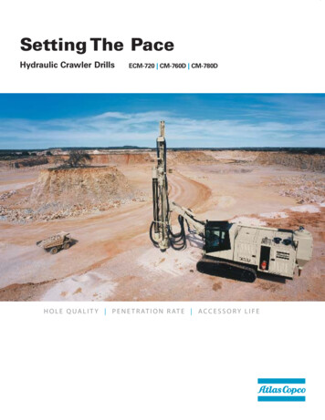
25. Maintenance KitsRefPart number QtyName1310 3003 74250/750 Hour Service KitFuel Filter (Primary) EngineFuel Filter (Final) EngineOil Filter-Engine500 Hour Service KitFuel Filter (Primary) EngineFuel Filter (Final) EngineOil Filter-EngineOil Filter-CompressorAir Filter-EngineAir Filter-Compressor1000 Hour Service KitFuel Filter (Primary) EngineFuel Filter (Final) EngineOil Filter-EngineOil Filter-CompressorAir Filter-EngineAir Filter-CompressorO-RingSealSeperator ElementSealKit - Oil Analysis1231111310 3003 7512345612345678910-1111111310 3003 7311111111111310 3083 46Remarks1310 9044 85 Rev. 001310 3011 7453
Atlas Copco instruction book: Atlas Copco logbook: Atlas Copco parts list: Motor parts list: Local Atlas Copco Representative Name: Address: Telephone: Contact persons: Service: Telefax: Parts: Example parts list Ref. Part number Qty Name Remarks 1 1310 0332 64 158 Screw - Round Head 2 1310 0326 91 2 Hinge .