Transcription
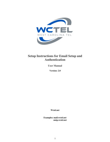
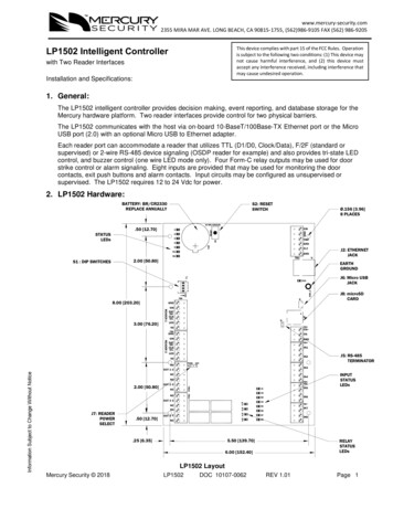
www.mercury-security.com2355 MIRA MAR AVE. LONG BEACH, CA 90815-1755, (562)986-9105 FAX (562) 986-9205This device complies with part 15 of the FCC Rules. Operationis subject to the following two conditions: (1) This device maynot cause harmful interference, and (2) this device mustaccept any interference received, including interference thatmay cause undesired operation.LP1502 Intelligent Controllerwith Two Reader InterfacesInstallation and Specifications:1. General:The LP1502 intelligent controller provides decision making, event reporting, and database storage for theMercury hardware platform. Two reader interfaces provide control for two physical barriers.The LP1502 communicates with the host via on-board 10-BaseT/100Base-TX Ethernet port or the MicroUSB port (2.0) with an optional Micro USB to Ethernet adapter.Each reader port can accommodate a reader that utilizes TTL (D1/D0, Clock/Data), F/2F (standard orsupervised) or 2-wire RS-485 device signaling (OSDP reader for example) and also provides tri-state LEDcontrol, and buzzer control (one wire LED mode only). Four Form-C relay outputs may be used for doorstrike control or alarm signaling. Eight inputs are provided that may be used for monitoring the doorcontacts, exit push buttons and alarm contacts. Input circuits may be configured as unsupervised orsupervised. The LP1502 requires 12 to 24 Vdc for power.2. LP1502 Hardware:BATTERY: BR/CR2330REPLACE ANNUALLYS2: RESETSWITCHØ.156 [3.96]8 PLACES3V BR/CR2330STATUSLEDsVINRESET12GND.50 [12.70]3TMPS24GNDBT15FLTR1GNDR22.00 [50.80]S1 : DIP SWITCHESJ2TB1EARTHGROUNDS1J6: Micro USBJACKD16VON GND C12348.00 [203.20]J6TB8J8VINDATD0CLKD1LEDJ5TB3VOTR TB9GNDTR-READER B5TB6OUT 2 CNCTB10NOTB11OUT 3 CJ7: READERPOWERSELECTIN5INPUTSTATUSLEDsIN6NCNO.50 [12.70]J5: RS-485TERMINATORIN3OUT 1 C2.00 [50.80]J8: microSDCARDGNDREADER 13.00 [76.20]J2: ETHERNETJACKOUT 4 CNC.25 [6.35]K1TB7K2IN7K3K4IN85.50 [139.70]RELAYSTATUSLEDs6.00 [152.40]LP1502 LayoutMercury Security 2018LP1502DOC 10107-0062REV 1.01Page 1
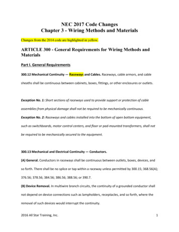
3. LP1502 Wiring and NDInputFLTCabinetGNDTamper InputPower InputTMPGNDVIN: 12 to 24 VdcNot -4CONNECTIONTB8-1TB8-2Power FaultTB8-3TB8-4TB8-5TB8-6TB9-1TB9-2GNDSIO Port(2-wire RS-485)Input 1Input 4Input 3Input 6Input 5Input 8Input 7Reader 2TB9-3TR- (B) See note -6TB11-1TB11-2TB11-3TB11-4TB11-5TB11-6TR (A) See note nput 2Reader 1Out 1Out 2Out 3Out 4GND: GroundDAT/D0: Data/Data 0/TR- (A)See note 1CLK/D1: Clock/Data 1/TR (B)See note 1BZR: Reader BuzzerLED: Reader LEDVO: Reader PowerGND: GroundDAT/D0: Data/Data 0/TR- (A)See note 1CLK/D1: Clock/Data 1/TR (B)See note 1BZR: Reader BuzzerLED: Reader LEDVO: Reader PowerNO: Normally Open ContactC: CommonNC: Normally Closed ContactNO: Normally Open ContactC: CommonNC: Normally Closed ContactNO: Normally Open ContactC: CommonNC: Normally Closed ContactNO: Normally Open ContactC: CommonNC: Normally Closed ContactNote 1: Terms A & B are from the RS-485 standardJumpers and Jacks:The LP1502 processor hardware interface is configured using jumpers to setup the reader port power andend of line termination.JUMPERSJ1J2J3J4J5J6J7J8SET ATDESCRIPTIONN/AFactory Use OnlyN/A10-Base-T/100Base-Tx Ethernet Connection (Port 0)N/AFactory Use OnlyN/AN/AOFFRS-485 EOL Terminator is OffONRS-485 EOL Terminator is OnN/AMicro USB Port (2.0)Reader Power Select. See Note 212V12 Vdc at Reader PortsPASS VIN "Pass Through" to Reader PortsN/AmicroSD CardNote 2:Install jumper J7 in the 12V position ONLY if the input voltage (VIN) is greater than 20 Vdc!Failure to do so may damage the reader or LP1502!Mercury Security 2018LP1502DOC 10107-0062REV 1.01Page 2
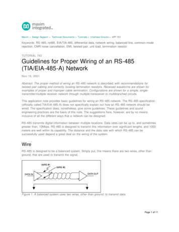
DIP Switches:The four switches on S1 DIP switch configure the operating mode of the LP1502 processor. DIP switchesare read on power-up except where noted. Pressing reset switch S2 causes the LP1502 to ionsNormal operating mode.After initialization, enable default User Name (admin) and Password(password). The switch is read on the fly, no need to re-boot.See IT Security section for additional information.Use factory default communication parameters.Use OEM default communication parameters. Contact systemmanufacture for details. See Bulk Erase below.ONONOFF OFF Bulk Erase prompt mode at power up. See Bulk Erase below.Makes the LP1502 report and function like an EP1502. To be used inXXXON situations where the host software has not been updated to supportthe LP series product line.All other switch settings for unassigned and are reserved for future use. X don’t care.ONONOFFOFFIn the factory or OEM default modes, downloaded configuration/database is not saved to flash memory.Factory Default Communication Parameters:Interface 1 (NIC1)Network: static IP address: 192.168.0.251Subnet Mask: 255.255.0.0Default Gateway: 192.168.0.1DNS Server: 192.168.0.1Primary Host port: IP server, Data Security: TLS if Available, port 3001, communication address: 0Alternate Host Port: Disabled4.Bulk Erase Configuration Memory:The bulk erase function can be used for the following purposes: Erase all configuration and cardholder database (sanitize board, less third party applications) Update OEM default parameters after OEM code has been changed Recover from database corruption causing LP1502 board to continuously rebootIf clearing the memory does not correct the initialization problem, contact technical support.Bulk Erase Steps:1.2.3.4.5.6.7.8.Do not remove power during steps 1-8.Set S1 DIP switches to: 1 & 2 "ON", 3 & 4 "OFF".Apply power to the LP1502 board. LED 1 on for about 15 seconds while LP1502 boots up.After the LP1502 boots up, watch for LEDs 1 & 2 and 3 & 4 to alternately flash at a 0.5 second rate.Within 10 seconds after the above pattern starts, change switches 1 or 2 to "OFF". If these switchesare not changed, the LP1502 board will power up using the OEM default communication parameters.LED 2 will flash indicating that the configuration memory is being erased.Full memory erase takes up to 60 seconds, usually a lot less.When complete, only LEDs 1 & 4 will flash for about 3 seconds.The LP1502 board will complete its initialization in 2 seconds after LEDs 1 & 4 stop flashing.5. Input Power, Cabinet Tamper and UPS Fault Input Wiring:Mercury Security 2018LP1502DOC 10107-0062TB1REV 1.01VINGNDThe LP1502 requires 12 to 24 Vdc power. Locate power source as close tothe unit as possible. Connect power with minimum of 18 AWG wire.Connect the GND signal to earth ground in ONE LOCATION within thesystem! Multiple earth ground connections may cause ground loopproblems and is not advised.Observe POLARITY on 12 to 24 Vdc input!There are two dedicated inputs for cabinet tamper and UPS fault monitoring.Normal (safe) condition is a closed contact. If these inputs are not used,install a jumper wire.TMPGNDFLTGND 12 TO 24 Vdc-CABINETTAMPERPOWERFAULTPage 3
6. Communication Wiring:The LP1502 controller communicates to the host via the on-board Ethernet 10-BaseT/100Base-TX portand/or the USB port (2.0) with an optional USB to Ethernet adapter.The serial I/O device communication port (TB3) is a 2-wire RS-485 interface which can be used to connectadditional I/O panels. The interface allows multi-drop communication on a single bus of up to 4,000 feet(1,219 m). Use 1-twisted pair with drain wire and shield, 120 ohm impedance, 24 AWG, 4,000 ft. (1,219m) maximum for communication.TB3TR TRGND1To serial I/O DevicesIMPORTANT NOTE! Install the termination jumper ONLY on the panel at each end of the RS-485bus. Failure to do so will compromise the proper operation of the communication channel!7. Reader Wiring:Each reader port supports a reader with TTL (D1/D0, Clock/Data), F/2F (standard or supervised) or 2-wireRS-485 signaling (OSDP reader for example). Power to the readers is selectable: 12 Vdc (VIN must begreater than 20 Vdc), or power is passed-through (PASS) from the input voltage of the LP1502 (TB1-VIN),300 mA maximum per reader port. Readers that require different voltage or have high current requirementsmust be powered separately. Refer to the reader manufacture specifications for cabling requirements. Inthe 2-wire LED mode the buzzer output is used to drive the second LED. Reader port configuration is setvia the host software.To fully utilize each reader port: TTL signaling requires a 6-conductor cable (18 AWG) F/2F signaling requires a 4-conductor cable RS-485 signaling requires two 2-conductor cables. Use one cable for power (18 AWG) and onecable for communication (24 AWG, with drain wire and shield)J7 – Reader Power SelectIf the input voltage to the LP1502 is 12 Vdc, jumper J7 MUST be in the PASS position.Typical D1/D0 or Clock/Data ReaderMercury Security 2018LP1502Typical 2-wire RS-485 Device(OSDP Reader for Example)DOC 10107-0062REV 1.01Page 4
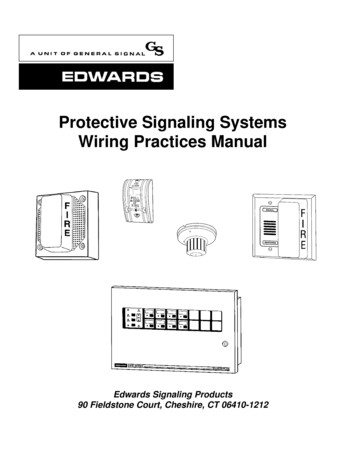
* Inputs on supervised F/2F readers may be unsupervised or supervised (supervised shown).TB8 or TB9TB8 or TB9 12 VdcVOLEDBZRD1/CLK/TR D0/DAT/TRGND 12 VdcVOLEDBZRDO (GREEN LED)D1D1/CLK/TR D0/DAT/TRGNDDO (GREEN LED)D1GROUND1GROUND1K,1%11K,1%DOOR MONITOR SWITCHNORMALLY CLOSED CONTACT *1K,1%1K,1%REQUEST TO EXIT SWITCHNORMALLY OPEN CONTACT *Typical Unsupervised F/2F ReaderTypical Supervised F/2F ReaderJumper D1 to LED on supervised F/2F readers8. Input Circuit Wiring:There are 8 inputs that are typically used to monitor door position, request to exit, or alarm contacts. Inputcircuits can be configured as unsupervised or supervised. When unsupervised, reporting consists of onlythe open or closed states. When configured as supervised, the input circuit will report not only open andclosed, but also open circuit, shorted, grounded*, and foreign voltage*. A supervised input circuit requirestwo resistors be added to the circuit to facilitate proper reporting. The standard supervised circuit requires1k ohm, 1% resistors and should be located as close to the sensor as possible. Custom end of line (EOL)resistances may be configured via the host software.* Grounded and foreign voltage states are not a requirement of UL 294 and therefore not verified by ULThe input circuit wiring configurations shown are supported but may not be typical:Terminal BlocksTB4 through TB7Standard Supervised Circuit,Normally Open Contact1K,1%1K,1%IN31K,1%1K,1%IN4Standard Supervised Circuit,Normally Closed ContactIN2 IN1Unsupervised Circuit,Normally Closed ContactUnsupervised Circuit,Normally Open ContactMercury Security 2018LP1502DOC 10107-0062REV 1.01Page 5
9. Relay Circuit Wiring:Four relays with Form-C contacts (dry) are provided for controlling door lock mechanisms or alarm signaling.Each relay has a Common pole (C), a Normally Open pole (NO) and a Normally Closed pole (NC). Whencontrolling the delivery of power to the door strike, the Normally Open and Common poles are typicallyused. When momentarily removing power to unlock the door, as with a mag lock, the Normally Closed andCommon poles are typically used. Check with local building codes for proper egress door installation.Door lock mechanisms can generate feedback to the relay circuit that can cause damage and prematurefailure of the relay plus affect the operation of the LP1502. For this reason, it is recommended that a diodebe used to protect the relay. Wire should be of sufficient gauge to avoid voltage loss.Diode Selection:Diode current rating: 1x strike currentDiode breakdown voltage: 4x strike voltageFor 12 Vdc or 24 Vdc strike, diode 1N4002(100V/1A) typical.10. Memory and Real Time Clock Backup Battery:The static RAM and the real time clock are backed up by a lithium battery when input power is removed.This battery should be replaced annually. If data in the static RAM is determined to be corrupt after powerup, all data, including flash memory, is considered invalid and is erased All configuration data must be redownloaded. Remove the insulator from the battery holder after installation. Battery type: BR2330 orCR2330.11. IT SecurityWhen installing the LP1502, it is important to ensure that it is done in a secure manner.Upon installation, the user accounts to the web configuration page should be created with securepasswords, and that all DIP switches are in the off position for the normal operating mode. The LP1502is shipped from the factory with a default login account, which is enabled when DIP 1 is moved from OFFto ON. The default login user name and password will be available for five minutes once enabled.Therefore, it is important that at least one user account is defined, and the DIP switches are set to OFFbefore the LP1502 is commissioned. It is also highly recommended not to configure the LP1502 with anIP address that is accessible from the public Internet.To further enhance network security, options are available to disable SNMP, Zeroconf discovery, as wellas the web configuration module itself. Additionally, data encryption can also be enabled over the hostcommunication port.12. Status LEDs:Power-up: All LED's OFF.Initialization: After power is applied or reset switch pushed, LED 1 is ON for about 15 seconds, thenLED’s 2, 3, 4, 5, 6, R1, R2, IN1, IN2, IN3, IN4, IN5, IN6, IN7 and IN8 are flashed once at the beginning ofinitialization. LEDs 3 and 4 is turned ON for approximately 1 second after the hardware initialization hascompleted, then the application code is initialized. The amount of time the application takes to initializedepends on the size of the database, about 1 second without a card database. Each 10,000 cards willadd about 2 seconds to the application initialization. When LED's 1, 2, 3 and 4 flash at the same time,data is being read from or written to flash memory, do not cycle power when in this state. If the sequencestops or repeats, perform the bulk erase procedure
Subnet Mask: 255.255.0.0 Default Gateway: 192.168.0.1 DNS Server: 192.168.0.1 Primary Host port: IP server, Data Security: TLS if Available, port 3001, communication address: 0 Alternate Host Port: Disabled 4. Bulk Erase Configuration Memory: The bulk erase function can be used for the following purposes: Erase all configuration and cardholder database (sanitize board, less third party .