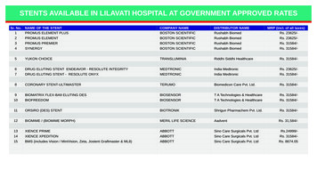
Transcription
OWNER’S MANUALGeniusTEAMBMPRO.COM
POWERING YOUR ADVENTURESBorn by the innovative spirit of our parent companySetec, with over 50 years’ experience in powersolutions, and design and manufacturing facilities inMelbourne, we are the leading experts in RV powermanagement.Inspired by the great Australian outdoors, we havecreated a range of rugged, smart and reliableproducts to power your adventures.Our range of battery chargers, monitors and powermanagement systems for caravans gives you peace ofmind when you are on the road, so that you can relaxin even the most far-flung destinations, knowing thatyou have control over your vehicle power.To learn more about the BMPRO range of products,please visit our website teambmpro.comTEAMBMPRO.COM
SAFETY PRECAUTIONSPlease read the Safety Precautions carefully before installing the powersupply. Be sure to observe all precautions without failAfter completing installation, conduct a trial operation to check for faults.WARNINGFailure to observe these instructions properly may result in personal injury, or lossof life.Ensure that there is good ventilation from the battery area.This appliance is not intended for use by young children or infirm persons withoutsupervision. Young children should be supervised to ensure that they do not playwith the appliance.Batteries are electrically alive at all times and must be treated with extreme caution.They can supply high short circuit currents, even if they appear damaged.Take care that dropping or touching of metal objects onto the battery cell does notcause short circuits.Remove any personal metal adornment such as a chain, watch or ring, which couldcause short circuits and personal injury.If the supply cord is damaged, it must be replaced by the manufacturer, its serviceagent or similarly qualified persons in order to avoid a hazard.
CAUTIONFailure to observe these instructions properly may result in property damage orpersonal injury, which may be serious depending on the circumstances.Refer to the installation section before operating. Correct installation is the mostcritical factor in ensuring the safe use of the power supply. If every consideration ofthese instructions has been satisfied the power supply will be safe to operate.Ensure that cable connections to batteries have the correct polarity and areprotected against accidental short circuit.Ensure that the shrouding supplied with the battery is fitted to the terminals.Before servicing a battery, disconnect the power supply from the mains supply.Do not attempt to charge non-rechargeable batteries. Charging a nonrechargeablebattery may result in the battery catching fire or possible explosion.Do not allow water or other liquids to enter the installation area.
6MANUAL PART 033930REV 1CThe BMPRO product range is proudly designed and manufactured in Melbourne, Australia,and represent a high-quality product that will power your adventures for years to come.Copyright 2019DISCLAIMER BMPRO accepts no liability for any loss or damage which may occur fromthe improper or unsafe use of its products. Warranty is only valid if the unit has not beenmodified or misused by the customer.
CONTENTSSAFETY PRECAUTIONS 4ABOUT THE GENIUS-II POWER SUPPLY 8DESCRIPTION OF PARTS 9INSTALLING THE GENIUS-II POWER SUPPLY10Personnel10Ventilation, Orientation and Thermal Considerations10Mounting10Mains Cable10Load, Battery and External DC Input Connections11Remote Load-Isolator Switch Connection14Battery Connection / Disconnection Procedure15BATTERIES16Paralleling Batteries16Storage17Deeply Discharged Batteries17SERVICING18FUNCTIONAL DESCRIPTION18Functional Diagram18AC/DC Power Supply19Fault Protection19Fusing19Battery Charging Features19Battery Charging Management20Battery Charging Store Mode20LED INDICATOR21SPECIFICATIONS22REPAIRS & AFTER-SALES SERVICE22WARRANTY TERMS AND CONDITIONS237
ABOUT THE GENIUS-II POWER SUPPLYThe Genius-II has been designed for use in caravans and similar recreationalvehicles, providing a DC power system with optional battery back up. Theunits operate from 240 Vac and provide an isolated 13.65 Vdc output at 35 Afor powering the load and charging the caravan battery. All the necessaryprotection and operating features for the load and battery are provided. Anoptional DC input is also provided to enable battery charging and poweringof the load from an external 13.8 V DC power source.The unit is fully enclosed ready for direct wall mounting. All connections areat the base of unit providing convenient wiring and installation. User accessto all load and battery fusing has been provided at the base of the unit.The Genius-II is available in two different battery charge currents.MODELBATTERY CHARGE CURRENTGenius-II Genius-IIA Genius-IIN15AGenius-IIH Genius-IIHA Genius-IIHN30ATable 1: Genius II Models and their respective maximum battery charge current ratingsWHAT’S INCLUDEDIncluded with this product are:99 Genius-II Power Supply99 Genius-II Owner’s Manual8
DESCRIPTIONOF PARTSNames and Functions of Parts1234561 Mains Cable (permanently1. MainsCableconnected)Connected)(Permanently240 V input power for charging the240V inputpowerchargingcaravanbatteryforandpowering loadsthe caravan battery and2 Mounting Bracketpowering loads3Illuminated Power Switch2. Mounting240 VBracketinput power switch3. IlluminatedPower Switch4 Load Fuses240 V inputpowerswitchTen fuses for the12 V loads5 Load4. LoadFusesTerminal Block, PositiveConnectionTen fusesfor the 12 V loads789 10 11 12 13 2Indicator8. 8 IndicatorMulti-colour statusindicatorMulti-colourstatusindicator9Battery Fuse9. BatteryFuseFuse forcaravan battery connectionFuseforcaravan battery10 Battery Negative TerminalconnectionConnection point for battery negativeterminal and external DC input10. BatteryNegative Terminalnegative wireConnection point for battery11 Battery Positive Terminalnegative terminal and externalConnection point for caravan batteryDCpositiveinput negativeterminal wire12BatteryExternalPositiveDC InputTerminalTerminalUsed for connecting the positive wire 11.Connection pointpoint forexternalDC input5. Load TerminalConnectionforcaravanof the 12 V Block,loads nal6 Heatsink Fins13 Remote Switch Terminal blockUsed forconnectingtheremovespositiveAir flowpast the finsexcess12. ExternalInputTerminalanTerminalDCblockfor connectingunitwire ofheatthefrom12 VtheloadsConnectionpointfor externaloptional remoteswitch.This switch is7 Load Terminal Block, Commonto disconnectthe loads from all6. HeatsinkFinsDCusedinputpositive wireNegative Connectionpower.Air flowpast the fins removesUsed for connecting the negative wire 13. Remote Switch Terminal blockexcessofheatfromthe unitthe 12V loadsTerminal block for connecting7. Load Terminal Block, Commonan optional remote switch. ThisNegative Connectionswitch is used to disconnect the 6Used for connecting the negativeloads from all power.wire of the 12 V loads9
INSTALLING THE GENIUS-II POWER SUPPLYPERSONNELInstallation is to be carried out only by suitable qualified personnel.VENTILATION, ORIENTATION AND THERMAL CONSIDERATIONSThe preferred orientation is with the cooling fins vertical and located suchthat there is a minimum of 80 mm free air space above and below them. Thisallows for the lowest operating temperature of the internal electronics andhence the highest reliability of the product.The final enclosure must also provide adequate ventilation to the outsideworld (or larger internal cavity) to prevent excessive heating of the air withinthe enclosure.The unit is rated to provide full power in both vertical and horizontalorientations with enclosure air temperatures up to 50 C.Note: The enclosure air temperature can easily exceed 50 C if adequateventilation is not provided.The unit has over-temperature protection, meaning it will shut down if itsinternal temperature rises above a safe level. The unit will automaticallyrestart once it has cooled to an acceptable level.WARNINGDo not install unit in same compartment whereflammable material such as petrol is stored.MOUNTINGThe Genius-II should be securely mounted to a suitably strong surface, usingthe two pre-drilled mounting brackets. Dimensional details are provided inFigure 1.MAINS CABLEThis is pre-cabled and fitted with AS/NZ mains plug ready for connection toan internal 240 V GPO. Ensure that the connection to the mains supply is inaccordance with the national wiring rules, and that the earth connection isinstalled.10
180 mm138 mmFour 5mm mounting holes328 mm316 mmFigure 1: Mounting holesFigure 1: Mounting holesLoad, Battery and External DC Input ConnectionsLOAD,BATTERY ANDEXTERNALINPUT CONNECTIONSAllDC connectionsshouldbe wiredDCaccordingto Figure 3 on page 11.AllDCconnectionsshouldbewiredaccordingFigure 3 canon page13. inA block diagram of the basic internal wiring of thetoGenius-IIbe foundA block5diagramFigureon page of15.the basic internal wiring of the Genius-II can be found inFigure 5 on page 13.Wire SizeWire SizeDC cables must be sized to carry the maximum full load current and to not exceedDC cablesbe sizedto carry theloadcurrentand to notthesystem mustvolt droprequirements.Themaximumfollowing fullcablesizesare recommended.exceed the system volt drop requirements. The following cable sizes areWhenrunning wires, if they pass through panels or wall, ensure the wires arerecommended.protected from damage by sharp edges. One option is to use cable glands.When running wires, if they pass through panels or wall, ensure the wires areCurrentMinimumSizeprotectedfrom damage by sharp edges. Oneoption isWireto usecable glands.0 – 10 A1.0 mm² or 18 AWG10 – 20 ACURRENT20 – 30 A0 — 10A3.0 mm² or 14 AWGMINIMUM WIRE SIZE5.5 mm² or 10 AWG1.0mm² or 18 AWGTable 2: Wire Size Recommendations10 — 20 A3.0mm² or 14 AWG20 — 30 A5.5mm² or 10 AWG811
Load ConnectionsConnectionsUp to 10 Loadindependently-fusedloads may beconnected.LoadsareattachedusingthetwoUp to 10 independently-fusedloadsmaybe10-way terminalconnected.blocks.Loads are attached using the two 10-way3.6mm min8.2mm maxterminal blocks.Refer to Table 2 for wire size recommendations.Refer to Table 2 for wire size recommendations.Where thewiresto thetoterminalblocks,Wheretheconnectwires connectthe terminalblocks, theythey shouldpreferablywitha spadeshouldpreferablybebe fittedfitted witha spadeterminal. Into fit intotheintoterminalblock, spadeterminalsterminal.orderIn orderto fitthe terminalblock,need to conformto conformthe dimensionsinspade terminalsneed toto theprovideddimensionsFigure 2.provided in Figure 2.Caravan Battery ConnectionFigure 2:Spade TerminalDimensionsFigure 2: Spade oncaravan battery to the terminals shown in Figure 3 on page 11.ConnectReferthe caravantheterminals shown in Figure 3 on page 13.to Table 2batteryfor wire tosizerecommendations.Refer to TheTable2 for connectionwire size recommendations.Thehaspositivehas an on-board fuse sonopositiveadditionalconnectionfusing is required.an on-board fuse so no additional fusing is required.External DC Input ConnectionSuitable fuse protection must be provided for the “DC In VE”External DCCAUTION:Input Connectioninput. A fuse rating not exceeding 30 Amps must be used.The power supply terminal “DC In VE” provides an alternative option forCAUTIONpowering of the load and chargingof the batteries when mains voltages are notpresent. This input is to be powered from a suitable 12 V system (e.g. your Car).Suitableprotectionmustbe providedfor theIn VE”Thevoltagefuseof thisexternal DCpowersource shouldnot“DCexceed14.8 V.input. A fuse rating not exceeding 30 Amps must be used.This input is diode isolated, so it is strictly an input; the Genius-II will never supplycurrent to anything connected to this terminal.The powerterminalinput“DCforIn a VE”providesan alternative option forThissupplyis the preferredcar ebatterieswhenmanagementmains voltagesNote: The Genius-II does not provide battery chargingwhen arenot present.Thisinputistobepoweredfromasuitable 12Vsystem(e.g.operating in this configuration (no mains, DC power provided through theexternalinput).this configurationcurrent andvoltage controlthe batterymust beyour Car).TheInvoltageof this externalDC powersourceforshouldnot exceed14.8 V. provided from the external source.SolarPanelisolated,ConnectionThis inputis diodeso it is strictly an input; the Genius-II will neversupply currenttoanythingconnectedthisThis is thepreferredCAUTION: Solar panels shouldtonotbe terminal.directly connected;a solarpanelinput forvoltagea car batteryregulatorconnection.must be fitted between solar panels and the battery.Solarpower shoulda seriesvoltageregulator)managementbe connected directlyNote: TheGenius-IIdoes (throughnot providebatterychargingwhen intothe caravan battery circuit. See Figure 3 on page 11.operatingin this configuration (no mains, DC power provided through thesolarInpowermay be wired directlyto thecaravanbattery,or toforthethecaravanexternal Theinput).this configurationcurrentandvoltagecontrolbattery must be provided from the external source.912
Fuse 810AFuse 710AFuse 610AFuse 510AFuse 410AFuse 310AFuse 210AFuse 110AFigure 3: DC Wiring Diagram12VCaravanBattery The solar regulator may beconnected at the Genius-IIor at the caravan battery asshown above.–Figure 3: DC Wiring Diagram Load 10–Fuse 910A.Fuse 1010A Load 1–12VSolarRegulator–12V Car Batteryor other DCsource–35AFUSEFuse for CaravanBattery/SolarRegulatorOptional SwitchFuses for Loads 1311Close to disconnectall Loads
Solar Panel ConnectionCAUTIONSolar panels should not be directly connected; a solar panel voltageregulator must be fitted between solar panels and the battery.Solar power should (through a series voltage regulator) be connecteddirectly into the caravan battery circuit. See Figure 3 on page 9. The solarpower may be wired directly to the caravan battery, or to the caravan batteryconnections on the Genius-II. Use whichever connection point is mostconvenient from a wiring perspective.Note: A solar panel voltage regulator with maximum output voltage notexceeding 14.8 V must be used at all times. In some situations the led canblink randomly, this is because the solar charger voltage is greater than thecharger voltage. This occurs only when the mains and the solar charger areboth present.REMOTE LOAD-ISOLATOR SWITCH CONNECTIONThe Genius-II allows for remote control of the load connections. A pairof contacts are provided for connection to the external switch. Whenthis switch is closed, all loads are disconnected from all power. Batterycharging is not effected by this switch. The switch current when closedis less than 1 mA, so any convenient switch and wire size may be used.14
BATTERY CONNECTION/DISCONNECTION PROCEDUREWARNINGSparks have the potential to cause an explosion should combustiblegases be present. The following procedures are designed to minimise therisk of spark generation while connecting or disconnecting the battery.Battery Connection ProcedureThe caravan battery should be connected as per the following steps.1. Remove mains power to the Genius-IITurn off the power switch on the Genius-II2. Disconnect all loadsTurn off all 12V equipment connected to the Genius-II3. Connect the positive battery terminal4. Connect the negative battery terminalIf the battery negative is connected to chassis, ensure a connection existsfrom chassis to the “Bat—VE” terminal of the Genius-II.Battery Disconnection ProcedureThe caravan battery should be disconnected as per the following steps.1. Disconnect all loadsTurn off all 12V equipment connected to the Genius-II ordisconnect the loads using the remove load-disconnect switch2. Remove mains power to the Genius-IITurn off the power switch on the Genius-II3. Disonnect the negative battery4. Disconnect the positive battery terminal15
BATTERIESNote: This battery charger is rated to charge lead acid batteries of up to 300Ah capacity. Charging current is limited to 15 A or 30 A depending on the typeof the model. Refer to About the Genius-II Power Supply.When using batteries with this product always consult with the batterymanufacturer for a detailed description of the installation, use andmaintenance of the battery.(AGM)and forGelchargingbatteries.This productis suitable12 V Sealed Lead-Acid (SLA) batteriesincluding Valve-Regulated Lead-Acid (VRLA) batteries, both AbsorbedCurrentBattery CapacityGlass Mat (AGM) Chargeand Gel Batteries.Chargin100 AhCHARGE CURRENT15 ABATTERY CAPACITY200 Ah100 Ah30 ATable8 hours4 ho200 Ah200 Ah16 hours8 ho100 Ah300 Ah4 hours12 h200 Ahtimes are based on8 continuoushours3: These chargecharging wibattery voltage greater than 10.5 V.300 Ah12 hoursParalleling BatteriesTable 3: These charge times are based on continuous chargingwith an initial battery voltage greater than 10.5VWhen paralleling batteries together, all the batteries MUST bePARALLELING BATTERIES of the same type, e.g. deep cycle batteryWhen parallelingtogether,all the batteries batteriesof the samecapacity,e.g. 100MUSTAh be:ofe.g.thedeepsamemanufacturer99 of the same type,cyclebatteryfully chargedbefore connecting them together99 of the same capacity,e.g. 100 Ah99 of the same manufacturer99 fully charged before connecting them togetherFigure 4:Recommended wiringfor connecting batteriesin parallel1616 h100 Ah15 A30 A8 hoCHARGING TIMESFigure 4: Recommended wiring for
WARNINGDo not install battery in the same compartmentwhere flammable material such as petrol is stored.STORAGEIf the caravan is to be stored for a long period of time, first fully charge thebattery and ensure all loads are disconnected. Recharge the battery at leastonce every 6 months. Regular recharging will prevent the battery frombecoming deeply discharged—a condition which can significantly shortenbattery life.DEEPLY DISCHARGED BATTERIESThis battery charger is not designed to charge deeply discharged batteries.Its effectiveness in charging such a battery is a function of the depth ofdischarge and the battery size. Bigger (higher capacity) batteries will bemore troublesome in this respect.In normal use a battery connected to the Genius-II should never becomedeeply discharged, so recharging it should never be a problem.If a battery has become deeply discharged and the Genius-II will not chargeit, remove the battery (see Battery Connection/Disconnection Procedure onpage 10) and charge it with a stand-alone charger. Once the battery voltagehas recovered to normal levels and the charge current is less than 15 A, itmay be reinstalled.17
SERVICINGThis product contains hazardous voltages and energy hazards, which canresult in death or injury. Only properly qualified service personnel mayservice it.There are no internal user serviceable parts. Only the fuses located in theexposed terminal block area are user serviceable.Isolate mains power, batteries and other DC input sources before servicing.Fuses: Only the DC output load and battery fuses may be replacedFuse ratings: Loads: 32 V Automotive mini-blade Fuse, 15A maximumBattery: 32 V Automotive regular blade Fuse, 35A maximumFactory-fitted FuseLoad fuses: 10 A FuseBattery fuse: 35 A FuseFUNCTIONAL DESCRIPTIONFunctional DescriptionFUNCTIONAL DIAGRAMFunctional DiagramDC IN VECar BatteryBATERY FUSECaravan BatteryReverseBatteryProtectionIsense3.3mΩVadjBAT VEBAT –VEBattery –VeLOAD FUSESL1 – L1010 x LoadOutputs–VEAC InputAC / DC10 x LoadReturnsLOAD SWITCHBattery Low-voltageDisconnect CircuitLoad Remotedisconnect CircuitRemote Loadon/off InputFigure 5: Functional SchematicFigure 5: Functional SchematicAC/DC Power Supply18This provides an isolated 13.65 V DC output for powering of the load andcharging of the battery. Battery current is sensed and monitored by the powersupply to limit the charging current to 15 A or 30 A maximum depending on themodel. Refer to About the Genius-II Power Supply.
AC/DC POWER SUPPLYThis provides an isolated 13.65 V DC output for powering of the loadand charging of the battery. Battery current is sensed and monitored bythe power supply to limit the charging current to 15 A or 30 A maximumdepending on the model. Refer to About the Genius-II Power Supply.FAULT PROTECTIONThe power supply provides automatic protection for overload including shortcircuit, over-voltage, over-temperature and reverse connected battery.In overload, short circuit, and over voltage condition the power supply willshut down. It will then automatically attempt to restart every 5 seconds untilsuch case that the fault is removed.FUSINGEach load circuit and the caravan battery connection have been fused toprovide fault protection and discrimination. Refer to the servicing section forfuse ratings.BATTERY CHARGING FEATURESThe power supply (Genius-II) provides full battery management as per thefollowing: The power supply is a three stage battery charger with Boost,Float, and Store charging modes to ensure long battery life. Chargingcurrent is limited to a maximum of 15 A or 30 A maximum depending on themodel. Details of the charging process can be found in the Battery ChargingManagement section below.The power supply is able to deliver 35 A maximum to the battery andloads on all models. For GENIUS-II, GENIUS-IIA and GENIUS-IIN, the 15 Abattery charging rate is only possible if the load current is 20A or less. If theload current exceeds 20 A, the maximum battery charging current will bereduced accordingly. The same logic goes for GENIUS-IIH, GENIUS-IIHA andGENIUS-IIHN models, but have maximum battery charge current of 30 A.Note that for the Genius-II to operate in the manner described above, allloads must be connected to load terminals, not directly to the caravanbattery.Low Voltage Disconnection of the batteries is provided to prevent deepdischarge of the battery. Automatic reconnection occurs when batteryvoltage recovers. Battery Current Drain is less than 3 mA.19
BATTERY CHARGING MANAGEMENTTo maintain the battery in a good state of health, an intelligently controlled chargingalgorithm is used. The purpose is to ensure that the correct voltages are appliedto the battery terminals at the appropriate times throughout its usage cycle. Thebasics of the charging algorithm are detailed in Figure 6.Charging AlgorithmWhen mains is interruptedduring Vfloat modeVfloat(13.65V)Vboost(14.05V)Vstore(13.25V)15 min24 HoursBattery VoltageVstore(13.25V)24 Hours24 HoursWhen mains is interruptedduring Store or PeriodicBoost modeFloat ModeStore ModePeriodic Boost ModeDuring Float mode the battery is charged at15 A until the float voltage is reached. Then itchanges to constant voltage charging.Store mode is activated when the battery hasbeen in Float mode for 24 hours (long enough forthe battery to be fully charged).If the float voltage has been reached and themains is interrupted for more than an hour, thenupon recovery of the mains the unit switches toBoost mode for 15 minutes and then returnsback to Float mode.During Store mode the unit switches to Boostmode for 15 minutes every 24 hours (calledPeriodic Boost mode).During Periodic Boost mode if the mains is lost formore than 2 minutes, then upon recovery of themains the unit switches to Float mode.Figure 6: Charging AlgorithmFigure 6: Charging AlgorithmBattery ChargingStoreSTOREMode icallyat 13.65V) thereis continuouschargingDuring Float(typicallyat 13.65V) thereis continuouschargingcurrent currentinto thein ainlongtermtermchargingsituationto causeonintothe battery,battery,sufficientsufficienta longchargingsituationto corrosioncause corrosionthethebatterypositiveplate.plate.To preventthis corrosionthe chargerwhatisonbatterypositiveTo preventthis corrosiontheutiliseschargerutiliseswhatcalleda Storagemode,wherethe chargingvoltagevoltageis reducedto 13.25 toV. 13.25In this V. Iniscalleda Storagemode,wherethe chargingis reducedmode the charging current is very small, usually less than the battery's selfthismode the charging current is very small, usually less than the battery’sdischarge current.selfdischarge current.If left continuously in Store mode, the battery would slowly discharge, so toIfpreventleft continuouslyin Storemode,the batterywouldslowlyoncedischarge,so tothis the chargerswitchesto Boostmode for15 minutesa day. Thispreventthistothechargerswitchesto Boost mode for 15 minutes once a day.is sufficientkeepthe batteryfully charged.Thisis sufficientkeep whichthe batterycharged.The netresult is atobatterycan befullyleft oncharge indefinitely without ouscharging.Theresultis a batterywhich canleft on chargeindefinitely without theusual battery degradation problems from continuous charging.1720
LED INDICATORIndicatorALEDmulti-colourLED indicator is provided to indicate the following operatingconditions.A multi-colour LED indicator is provided to indicate the following operatingconditions:ColourConditionGreen (Solid)Mains present AND battery fully charged(battery charging current less than 1 A)Green (Flash)Mains present AND battery charging AND loadsconnectedGreen (Blink)No Mains and battery voltage above disconnectvoltage (the battery is powering the loads)Red (Solid)Mains present AND battery connected ANDpower supply in over-temperature shutdownmodeRed (Flash)Mains present AND battery fuse blownRed (Blink)Loads disconnected via remote disconnectionswitchRed and/orGreen flashesof unspecifieddurationOutput overload orOther unspecified faultTable 4: LED IndicationsNotes:a)b)c)LED on continuouslyTypically 0.25 second on, 0.25 second offTypically 0.25 second on, 4 second off1821
SPECIFICATIONSInput Voltage240 Vac nominal, 10%, 50/60 Hz. The power supply willwithstand a 5 min 15 % surge on the maximum nominal voltageInput Surge 40 A (cold start)Holdup Time 10 mS at full load current and over nominal input voltageoperating rangeOutput Current35 A Continuous (load battery current)Factory Set Voltage13.65 V /0.1 V (Float voltage)Load Regulation 2%Output Ripple Voltage 150 mVOver Voltage Protection 17 VOver Current Protection35 A to 38 A (load battery current)Battery Current Limit15 A 1 A (GENIUS-II, GENIUS-IIA and GENIUS-IIN)30 A 3 A (GENIUS-IIH, GENIUS-IIHA and GENIUS-IIHN)Battery Connect11.5 0.2 VDisconnect10.0 0.2 VBattery Drain 3 mAEfficiency 84 %Cooling FanThermally controlledAmbient0 C – 50 CWeight3.7 kgStandardsSafety: AS/NZS 60335.1, AS/NZS 60335.2.29 EMC: AS/NZSCISPR 22 Class A Compliance: ERACREPAIRS AND AFTER-SALES SERVICEPlease consult your BMPRO dealer.WARNINGDo not disassemble, modify, or repair the unit.Doing so may result in electric shocks or fire.22
WARRANTY TERMS AND CONDITIONSRegistering your BMPRO product is an important step to ensure that you receive allof the benefits you are entitled to. Please visit www.teambmpro.com to complete theonline registration form for your new product today.1. BMPRO goods come with guarantees that cannot be excluded under AustralianConsumer Law. You are entitled to a replacement or refund for major failure and forcompensation for any reasonably foreseeable loss or damage. You are entitled tohave the goods repaired or replaced if the goods fail to be of acceptable quality andthe failure does not amount to a major failure. The benefits under this Warranty arein addition to your other rights and remedies under a law in relation to the goods towhich this Warranty relates (Australian Consumer Law).2. BMPRO warrants products against defects for a period of two years, commencingfrom the original date of purchase. Proof of purchase is required before you canmake a claim under this warranty.HOW TO PROTECT YOUR RIGHTS UNDER THIS WARRANTY:3. The GENIUS II is designed to be installed by a suitably qualified installer. You oryour installer should carefully inspect the product before installation for any visiblemanufacturing defects. We accept no responsibility in addition to our consumerguarantee obligations where a product has been installed incorrectly.4. This warranty does not extend to product failures or defects caused by, orassociated with, but not limited to: failure to install or maintain correctly,unsuitable physical or operating environment, accident, acts of God, hazard,misuse, unauthorised repair, modification or alteration, natural disaster, corrosiveenvironment, insect or vermin infestation and failure to comply with any additionalinstructions supplied with the product.5. BMPRO may seek reimbursement of any costs incurred by BMPRO when a productis found to be in proper working order or damaged as a result of any of the warrantyexclusions mentioned in point 4 of this statement.6. To enquire or make a claim under this warranty, please follow these steps:a) Prior to returning a BMPRO product, please email service@teambmpro.comto obtain a Return Material Authorisation (RMA) numberb) Package and send the product to:BMPRO Warranty Department19 Henderson RoadKnoxfield, VIC 3180Please mark RMA details on the outside of the packagingc) Please ensure the package also includes: a copy of the proof of purchase,a detailed description of the fault and your contact details including phonenumber and return address.7. BMPRO will not be liable for any costs, charges or expenses incurred in the processof returning a product in order to initiate a warranty claim23
POWERING YOUR ADVENTURES.TEAMBMPRO.COMBMPRO 61 3 9763 0962 sales@teambmpro.com19 Henderson Rd, Knoxfield VIC 3180 Australiateambmpro.com
Connection point for battery negative terminal and external DC input negative wire 11. Battery Positive Terminal Connection point for caravan battery positive terminal . All DC connections should be wired according to Figure 3 on page 13. A block diagram of the basic internal wiring of the Genius-II can be found in Figure 5 on page 13.