Transcription
APPENDIX F: TUNNELSYSTEMSI-81 Independent Feasibility Study November 2017 APPENDIX F
TABLE OF CONTENTS1TUNNEL SYSTEMS151.1Introduction 11.2Fire Protection and Life Safety Provisions 11.3NFPA 502 Compliance and Authority Having Jurisdiction 11.4Tunnel Ventilation1.5Standards of Reference 21.6Critical Determinations1.7Normal Ventilation1.8Portal Emissions1.9Portal Air Recirculation223341.10 Continuous Emission Monitoring641.11 Emergency Ventilation and Smoke Management 41.12 Egress Passage or Stairway Pressurization 41.13 Tunnel Ventilation System Operation41.14 Recommended Ventilation Options for I-81 Tunnel Alternatives1.15 Summary234i6TUNNEL FIRE PROTECTION & SUPPRESSION SYSTEMS872.1Overview 82.2Applicable Standards 92.3Fire Protection System Design Considerations 9TUNNEL LIGHTING103.1Overview 103.2Standards and References 103.3Design Consderations 103.4Tunnel Lighting Control Systems 103.5Tunnel Lighting Fixture Circuiting 103.6Tunnel Lighting Fixtures 103.7Tunnel Egress Stairwells and Ancillary Spaces 113.8Tunnel Fixed Message Sign lighting 113.9Approach Lighting 11TUNNEL FINISHES512I-81 Independent Feasibility Study November 2017 APPENDIX F4.1Overview 124.2Codes, Standards & References4.3Highway Architecture Elements 124.4Interior Tunnel Elements4.5Tunnel Emergency Egress 15ELECTRICAL SYSTEMS1212165.1Overview 165.2Power Distribution System5.3Fire Alarm and Detection Systems 175.4Emergency Communication Systems5.5Security Systems5.6Supervisory Control, Monitoring and Data Acquisition (SCADA) System5.7Traffic Control5.8Typical Dynamic Message System16171718TUNNEL DRAINAGE SYSTEMS18196.1Overview 196.2Applicable Standards6.3Drainage System Discharge Considerations6.4Drainage System Capacity Basis6.5Drainage System Piping6.6Drainage System Pumps and Pump Stations 1919191919TUNNEL OPERATIONS AND MAINTENANCE 207.1Overview 207.2Operations & Maintenance Plan 207.3Concept of Operations2017
FIGURESTABLESFIGURE 1:Fire and Life Safety Committee (FLSC) Process 2TABLE 1:Design Fire Data Based on Vehicle Type (NFPA 502) 3FIGURE 2:Jet Fan System (from NFPA 502) 2TABLE 2:Summary of Ventilation Options (refer Table 3 and Table 4 for ventilation scheme details) 6FIGURE 3:Semi-Traverse Point Exhaust System (from NFPA 502) 2TABLE 3:Summary of Ventilation Schemes for Twin Bore Tunnel Alternatives (Red, Blue and Orange alternatives)FIGURE 4:Portal Emission PreventionTABLE 4:Summary of Ventilation Schemes for Single Bore Stacked Tunnel Alternatives (Green A alternative)FIGURE 5:Smoke Extraction via Point Exhaust 4TABLE 5:Recent US Tunnels with FFFSFIGURE 7:Single Bore Stacked Tunnel with Jet Fan InstallationTABLE 6:Daytime Supplemental Lighting Consideration 10FIGURE 6:Twin Bored Tunnel with Jet Fan Installation 5FIGURE 9:Activated FFFSFIGURE 8:Typical Standpipe Hose Valve Cabinet 9356789FIGURE 10:Construction Photo of Twin Bored Tunnel Portals and Approach Roadway Section 12FIGURE 11:View of Bored Tunnel Showing Finish Features 12FIGURE 12:Stainless Equipment Cabinet for Fire Hose Valve and ExtinguisherFIGURE 13:Example of Various Types of Signs Utilized in Road Tunnels to Identify Safety Related FeaturesFIGURE 14:Tunnel Emergency Egress131313FIGURE 15: Photo showing egress opening, traffic barrier with angled interruption, painted board fireproofing, signage,and equipment cabinets 13FIGURE 16:Photo Showing Raised Safety Walk in Concrete Traffic Barrier 13FIGURE 17:Stainless Steel Sliding Egress DoorFIGURE 18:Construction Photo Showing Stainless Steel Sliding Egress Door inside Egress CorridorFIGURE 19:Stacked Single Bore Tunnel with Interconnecting Egress Stairs (Seattle Tunnel, WA) 151414FIGURE 20: Twin Bored Tunnel Configurations with Cross Passages (bores can be at the same level or different levels(WSP USA renderings)) 15FIGURE 21: Cross Passage between Two Bored Tunnels Showing sliding door (open at far end), illuminated exit sign,equipment cabinets, pressurization fans, and emergency lighting fixtures (Port of Miami Tunnel) 15FIGURE 22: Cross Passage between Two Bored Tunnels (showing sliding door (open at far end), illuminated exit sign,equipment cabinets, pressurization fans, and emergency lighting fixtures (Port of Miami Tunnel)) 15FIGURE 23:Rendering of Single Bore Stacked Tunnel Option15FIGURE 24:Tunnel Incident Viewed on Closed Circuit Television SystemFIGURE 25:Dynamic (Variable) Message Signs (DMS)FIGURE 26:Typical Lane Use Signals 18FIGURE 27:Tunnel Centralized Control and Operations ConceptFIGURE 28:Example Control Room18182121APPENDIX F I-81 Independent Feasibility Study November 2017ii
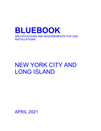
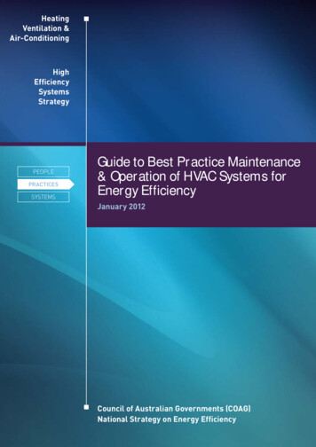
1 TUNNEL SYSTEMS1.1 INTRODUCTIONsafety provisions required by NFPA 502 are based on thetunnel’s length and a site-specific assessment.Each of the alternative tunnel options being consideredfor I-81 will require a variety of operational systems andfeatures within the tunnel in order to support safe trafficoperations and to provide the necessary level of fireprotection and life safety. The various tunnel systems andfeatures that will be required include:The I-81 tunnel alternative study area is an urbancorridor that can be assumed to have a generally highvolume of traffic inclusive of cars, buses and heavy goodsvehicles. Emergency response agencies are assumed tobe available within generally close proximity. Based onthis, and the fact that the four tunnel alternatives beingconsidered range between 1 mile to 2 miles in length, thefire protection and life safety requirements will be thesame for each tunnel alternative and will include provisionof the following:oo Traffic control and monitoringoo Roadway lightingoo Electrical poweroo Communicationsoo An engineering analysis to establish overall fire protection and life-safety conceptoo Equipment control and monitoring (SCADA)oo Means for emergency egress and accessoo Securityoo Tunnel ventilationoo Fire detection and alarmoo Tunnel fire suppression systemoo Fire protection and suppressionoo Tunnel drainage systemsoo Ventilationoo Traffic control and monitoringoo Drainageoo Tunnel emergency lightingoo Emergency egressoo Fire alarm and detectionoo Tunnel finishesoo Electrical power distributionoo Emergency communications11.2 FIRE PROTECTION AND LIFE SAFETYPROVISIONSoo Structural fire protectionThe specific requirements for the systems and elementsnecessary to meet the fire protection and life safetygoals for any of the tunnel alternatives being consideredfor I-81 would be based on the minimum requirementsestablished in National Fire Protection Association (NFPA)502 Standard for Road Tunnels, Bridges, and OtherLimited Access Highways. The fire protection and lifeoo Emissions monitoringI-81 Independent Feasibility Study November 2017 APPENDIX Foo Exit and other special signageoo Intrusion detection/access controloo Emergency and incident management plansThe above provisions have certain prescribed aspectsmany of which are performance-based. For example, akey requirement in NFPA 502 is the ability to establishtenable conditions in the case of a fire event in orderto provide a safe path for the evacuation of motoristsand to also facilitate response by fire fighters and otheremergency personnel. Achieving these goals relies on theinteraction of the tunnel ventilation system, available meansof emergency egress and fire control. The assessment ofwhether or not tenable conditions are achievable can besubjective and depends on several factors, including butnot limited to, the design fire, egress locations, ventilationapproach, and provision of firefighting systems. NFPA 502requires an engineering analysis that holistically considersthe interaction of all available provisions and their abilityto achieve the overall fire protection and life safety goal.oo Emergency medical servicesGiven the potential for subjective interpretations andapproaches when developing a performance-basedapproach to fire-life safety design, a consensus approachbetween stakeholders is needed in order to develop acredible set of design criteria, design basis and subsequentdesign. The Authority Having Jurisdiction (AHJ) is a criticalstakeholder in this consensus approach to development ofa fire-life safety strategy and design.oo Design consultants1.3 NFPA 502 COMPLIANCE AND AUTHORITYHAVING JURISDICTIONNFPA 502 defines the Authority Having Jurisdiction as “anorganization, office, or individual responsible for enforcingthe requirements of a code or standard, or for approvingequipment, materials, an installation, or a procedure”.In most municipalities the AHJ is a designee of the fireservices (either local or state) such as the fire marshal ordistrict chief; however, in certain jurisdictions the designatedAHJ may be the tunnel owner or operating authority asthey have the overall responsibility for the facility. For alarge infrastructure project like the development of a roadtunnel for the I-81 corridor through Syracuse, a varietyof other agencies and stakeholders will have formal andinformal input during the planning process. For instance,the following organizations would be expected to havea significant role in defining and planning the trafficoperations, life safety goals, incident management andemergency preparedness and response:oo First responders (local fire and police)oo State policeoo Hazardous material/spill unitsoo New York State Department of Transportationoo Federal Highway Administrationoo City of Syracuseoo Local and state permitting and regulatory agenciesNFPA 502 defers to the Authority Having Jurisdiction(AHJ) for the enforcement of its provisions. Therefore, theapproach toward the implementation of NFPA 502 beginswith the identification of the AHJ. It is then recommended thata “Fire and Life Safety Committee” (FLSC) be establishedto engage in a partnered approach with the key projectparticipants, agencies and stakeholders in establishingthe life safety design goals to be implemented as partof the tunnel design and construction phases, and ensuringthey are in unison with the tunnel’s operational conceptfor emergency and incident management response. Theprotocol of the FLSC will be to act as the technical andpolicy overseer for the safety issues affecting the tunneland to make all key decisions and determinations byconsensus. During preliminary planning stages the ownershould facilitate a FLSC process and document the decisionsas part of a NFPA 502 Compliance Report. The report willdocument all decisions made relative to the implementationof NFPA 502, including any traffic restrictions such asbanning of bulk fuel carriers and other hazardous cargovehicles, and identify any specific exceptions. This reportwould then serve as the “AHJ approved” life safety designcriteria for the tunnel. The graphic below outlines therecommended FLSC process.
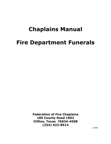
FIGURE 1:Fire and Life Safety Committee (FLSC) ProcessFIGURE 2:Jet Fan System (from NFPA 502)1.4 TUNNEL VENTILATION1.5 STANDARDS OF REFERENCEVentilation is a critical key to providing safe conditionswithin road tunnels. During normal traffic operations,ventilation is required to maintain the in-tunnel air qualityby preventing the dangerous accumulation of vehicleemitted pollutants (i.e., carbon monoxide, CO, and oxidesof nitrogen, NOx) and to maintain visibility in the tunnel bypreventing the accumulation of haze-producing pollutants.In the event of a fire emergency the tunnel ventilationsystem performs a major role in providing life safetysupport by controlling the flow of smoke and heat in amanner that protects motorists and facilitates evacuationand fire fighter access.The design of road tunnel ventilation systems will berequired to conform to the latest issues of the followingstandards and references:For normal tunnel operations, the tunnel length,traffic volume, and the direction of traffic movement(unidirectional versus bidirectional) are some of the keyfactors in determining whether the ventilation requirementscan be achieved by passive means (the piston actionairflow generated by the moving vehicles) or whethermechanical ventilation is required. The tunnel length isalso a key factor in determining the need for mechanicalventilation during emergency operations, since it affectsthe overall pollution being emitted from the tunnel, and fora fire it affects the egress time from the tunnel, the numberof motorists that could be exposed to the hazards of a fire,the degree of difficulty for fire department or emergencyservices intervention (longer is more difficult to access) andthe overall probability of a fire (longer tunnels will have agreater fire probability).Based on modern US road tunnels comparable to the I-81tunnel alternatives being considered herein, a mechanicalventilation system will be required. The installed ventilationsystem capacity will ultimately be determined by therequirement for emergency smoke control during a tunnelfire incident (emergency operations). The ventilationrequirements during normal tunnel operation (non-fireconditions) will be significantly less and determined by theprevailing traffic conditions.The most likely applicable ventilation options for thevarious tunnel alternatives being considered herein forI-81 include a longitudinal system utilizing in-tunnel jet fans(Figure 2), a semi-transverse point exhaust using a ductand operable dampers (Figure 3) or, in the case of thelonger tunnel alternatives, a combination of both systemtypes.FIGURE 3:oo National Fire Protection Association – Standard forRoad Tunnels, Bridges, & Other Limited Access Highways (NFPA 502).oo American Society of Heating, Refrigeration, and AirConditioning Engineers (ASHRAE) – Enclosed VehicularFacilities.oo Recommended AASHTO Guidelines for EmergencyVentilation of Smoke in Road Tunnels.oo FHWA/EPA Guidance on CO Levels in Tunnels.1.6 CRITICAL DETERMINATIONSThere are critical determinations to be made by theFLSC that will have a fundamental influence and affectto the overall approach to fire protection, life safetyconsiderations, emergency response planning and tunnelsystem design in general which must be made in theearly phase of any road tunnel project. These criticaldeterminations are as follows:1.6.1 DESIGN FIREThe tunnel design fire is the fire size (heat release rate) thatshall be considered in the design and planning for the fireprotection and life safety provisions required. Therefore,selection of the design fire becomes one of the most criticaldeterminations to the design of the tunnel systems. Forexample, NFPA 502 states the following: “The design ofthe emergency ventilation system shall be based on a firescenario having defined heat release rates, smoke releaserates, and carbon monoxide release rates, all varying asa function of time. The selection of the fire scenario shallconsider the operational risks that are associated withthe types of vehicles expected to use the tunnel. The firescenario shall consider fire at a location where the moststringent ventilation system performance requirement isanticipated by an engineering analysis.”Semi-Traverse Point Exhaust System (from NFPA 502)APPENDIX F I-81 Independent Feasibility Study November 20172
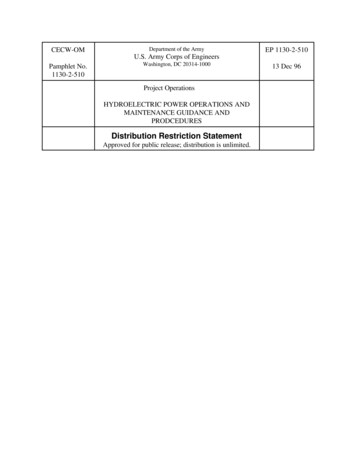
1.6.2 TRAFFIC TYPE AND HAZARDOUS CARGODefining the normal traffic mix and allowable vehicletypes is a critical determination necessary to selecting theappropriate design fire. Per NFPA 502, “The selection ofthe design fire size (heat release rate) shall consider thetypes of vehicles that are expected to use the tunnel.”Given that I-81 is a major highway, it is reasonable toassume that a traffic fleet mix of cars, buses and heavygoods trucks would use the tunnel. However, should a tunnelalternative be implemented, it is necessary that the FLSCconsider that fuel tankers and other regulated hazardouscargo vehicles be re-routed and not allowed to use thetunnel. I-481 provides a viable alternative interstate route.The practice of banning these types of vehicles from roadtunnels is common practice in all US cities.Table 1 has been excerpted from NFPA 502 and providesguidance on the magnitude of possible vehicular fires withrespect to the types of vehicles that could use the tunnel.In assessing this data it is reasonable to assume that amultiple vehicle fire involving large heavy goods vehiclessuch as semi-trailer trucks could potentially reach amagnitude of up to 200 MW, according to NFPA 502. Therepresentative fire heat release rate (FHRR) is 150 MW.Inclusion of a fixed firefighting system can be used as abasis to adopt a lower FHRR in the order of 70 – 100MW.1.7 NORMAL VENTILATIONDuring normal operating conditions the tunnel is expectedto self-ventilate with free-flowing traffic. The piston actionventilation caused by traffic movement will be sufficient tomaintain safe CO and opacity levels in the tunnels duringfree-flowing traffic conditions. Ventilation may need tobe operated to provide dilution air during heavy trafficperiods, when traffic speeds fall below 10 to 15 mph, andduring adverse outdoor wind conditions. The tunnels willbe continuously monitored for trends in the CO levels andrising CO levels will indicate the need for more dilution air,therefore additional pairs of fans would be activated untilthe CO levels are at acceptable levels.3I-81 Independent Feasibility Study November 2017 APPENDIX FThe ventilation system must be sufficient to dilute thevehicle-emitted pollutants to safe levels. The limitingpollutant concentrations during normal tunnel operationshave been established jointly by the FHWA and EPA. Theguidelines are given in terms of allowable average COconcentration versus exposure time. In the US, CO is theprimary pollutant of concern due to the large percentageof gasoline powered vehicles. Using ventilation tomaintaining acceptable CO levels in a tunnel will alsosufficiently maintain acceptable levels for all other vehicleemission constituents.a longitudinal ventilation system may cause emission levelsfrom the tunnel portals to be in excess of allowable levels.In this instance a ventilation scheme whereby vitiated airis exhausted just prior to the exit portal and ejected via atall vertical stack (Figure 4) would be required.Fan operation during normal tunnel operations willbe determined primarily on the basis of the carbonmonoxide (CO) level in the tunnel. The tunnels should becontinuously monitored for CO at a suitable number oflocations. In addition, if a relatively large percentageof diesel powered trucks and buses are anticipated itis recommended to monitor the opacity of the tunnel air(haze) to ensure a safe level of visibility. The monitoreddata can be transmitted to control room where the datawill be displayed for use by the system operators andautomatic control system.1.8 PORTAL EMISSIONSDuring normal operations the vehicle piston effect isgenerally sufficient to provide dilution of vehicle emissionswithin the tunnel and analysis will be required at thedesign phase to confirm and quantify pollution levelsduring peak and non-peak traffic conditions. Compliancewith environmental regulations with regard to pollutionlevels external to the tunnel will need to be demonstratedand approved.TABLE 1:Design Fire Data Based on Vehicle Type (NFPA 502)An ambient air quality analysis of the emissions fromthe tunnel portals will be necessary with respect to anysensitive receptors in the surrounding areas near to theexit portals. This ambient air quality analysis will need toincorporate the expected tunnel traffic on an hourly basis,the subsequent vehicle emissions, the expected airflowin the tunnel, and the impact of external meteorologicalconditions.Emissions from the tunnel portals and achieving air qualitycompliance will be critical. If this cannot be achievedthen ventilation buildings at each portal may be requiredto eject and disperse vitiated air away from sensitivereceptors. In the case of the longer tunnel alternative, use ofFIGURE 4:Portal Emission Prevention
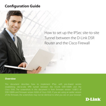
1.9 PORTAL AIR RECIRCULATIONRecirculation of vitiated air at tunnel portals needs to befactored into a design if a system without point exhaustnear the portal is used. Recirculation of vitiated air istypically managed by offsetting portals (by around 300feet) or by providing a dividing wall structure.1.10 CONTINUOUS EMISSION MONITORINGEmission monitors will be required in all tunnel alternativesto continuously monitor the levels of various pollutants andoverall visibility. These systems will be utilized duringnormal traffic operations to regulate the ventilation systemas needed for dilution of accumulated emissions or tosignal an alarm when emission levels are exceeding theirpreset safe levels.1.11 EMERGENCY VENTILATION AND SMOKEMANAGEMENTIn the case of a vehicle fire in the tunnel, longitudinalventilation systems control the flow of smoke by producinga sufficient air velocity along the roadway to force thesmoke movement downstream away from the fire site andthe section of a tunnel most likely occupied by trappedmotorists. The minimum air velocity required for smokecontrol is referred to as the critical velocity, that velocitywhich prevents reverse flow or back layering of smoke. Themagnitude of the critical velocity is a function of the designfire heat release rate (fire size), the tunnel dimensions andthe tunnel grade. The air flow induced in the tunnel mustbe sufficient to overcome the various resistances to flow(including vehicles in the tunnel, tunnel grade, adversewinds, etc.), while also exceeding the critical velocity.Emergency ventilation and smoke management via a pointexhaust system is achieved via a longitudinal duct (eitherover the roadway or in the side wall) with individuallyoperable dampers. A schematic is provided in Figure5. With a point exhaust system smoke is extracted fromthe roadway into a dedicated duct and dispersed via aremote fan shaft or fan building. The system is designedto contain smoke at/near the site of the fire and providetenable conditions within the tunnel both upstream anddownstream of the incident. Point exhaust systems havebeen implemented in tunnels in Europe and Australia andcurrently is being implemented in the Alaska Way Tunnelin Seattle. Point exhaust systems require a dedicated ductalong the length of the tunnel and a large number ofindividually controlled dampers. In addition, an ancillaryfacility is required as a centralized location to house theexhaust fans serving the duct.1.12 EGRESS PASSAGE OR STAIRWAYPRESSURIZATIONDuring a significant tunnel fire event where evacuationmay be necessary, pressurization of the egress paths(cross-passages or stairways) is needed to prevent smokeingress and contamination of egress route. In many cases,cross-passageways and stairways can be pressurized byoperation of the ventilation system in the connecting (nonincident) bore. Where this is not achievable a dedicatedfan system may be necessary to provide sufficientpressurization of these spaces.1.13 TUNNEL VENTILATION SYSTEM OPERATIONFor major urban road tunnels, such as that beingconsidered for I-81, operation of ventilation systemsduring normal traffic conditions is typically arranged tobe automatic based on pre-set level indications receivedfrom the emission monitoring system. In addition, alert/alarm indications regarding environmental conditions arealso sent to a central operations control center so that anysystem adjustments can be manually made by a tunneloperator.Jet fan based longitudinal ventilation systems do notrequire significant operator interaction or decision makingthat can lead to a delayed or incorrect response duringa fire emergency. A point exhaust system requires thedampers near to the fire to be operated and, in thecase of a vehicle fire, the appropriate response mode isdependent on the exact location of the fire within the tunnel.The ventilation system operation control software can bepreprogrammed to operate the system in the appropriatemode based upon the operator’s identification of the firelocation.FIGURE 5:Smoke Extraction via Point ExhaustAPPENDIX F I-81 Independent Feasibility Study November 20174
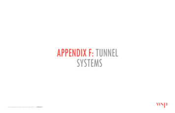
1.14 RECOMMENDED VENTILATION OPTIONS FORI-81 TUNNEL ALTERNATIVESThere are four tunnel alternatives identified herein forthe potential replacement of the I-81 corridor throughSyracuse, NY. The tunnel alternatives identified consistof differing length and alignment alternatives using twodistinctly different variations of bored tunnel construction.Each of the tunnel alternatives have been developed fortwo 12’ travel lanes with minimum 4’ shoulders on eachside of the travel lanes, both northbound and southbound.Vertical vehicular clearance throughout is set at 16.0’.The predominant bored tunnel variation for the differentalternatives is a “single bore - stacked” tunnel with an upperand lower deck level that allow for the accommodation ofnorthbound and southbound traffic separately. The GreenA alternative assumes a single bore stacked tunnel option,and is approximately 5,800 feet in length.The other bored tunnel variation being considered isreferred to as the “twin bored tunnel” alternative whichessentially consists of two separate and parallel boredtunnels that provide the necessary separation of northboundand southbound traffic. Alternatives considering the twinbore option range between 8,600 feet and 2.8 miles inlength.A longitudinal tunnel ventilation system using jet fansis recommended as the ventilation system design basisfor each tunnel alternative with the inclusion of a pointextraction system for the longer tunnel alternatives.A jet fan based longitudinal ventilation system utilizes thejet fans to impart a high velocity air jet into the tunnelwhich induces a longitudinal flow along the length of thetunnel. The longitudinal flow in the tunnel pulls air into theentrance portal, and then the air travels the full length ofthe tunnel and is discharged out the other portal (optionsT1 and S1) or exhausted via a single extraction point(options T2, T3, S2 and S3).Jet fan units are usually rated for high temperatureoperation as they are mounted in the tunnel and willbe exposed to elevated temperatures in the event of avehicle fire. In accordance with NFPA 502, the fans, theirmotors, and all related components that are exposed tothe air stream must be able to remain operational for aminimum of 1 hour in an air stream temperature of 482deg F (250 deg C). The system design will need to includean additional pair of fans in the tunnel bore to allow forthe potential loss of a pair of fans by heat damage duringa fire.External wind conditions can have a significant effect onthe operation of the longitudinal ventilation system. If thewind is acting opposite to the direction of ventilation, thenthe tunnel airflow will be reduced. The jet fan selectionsneed to include the effect of adverse wind acting on theexiting portal.Jet fans require a minimum clearance envelope in the order of6’. For the twin bore tunnel options being considered for I-81the diameter of the each tunnel bore is generally establishedbased on the number of travel lanes, travel lane width, shoulderrequirements, and vehicle height clearance. These parametersgenerally result in a tunnel diameter that is able to accommodate jet fans mounted in the crown of the tunnel above the vehicle clearance envelope. Refer to Figure 6 for a single boretunnel with a stacked road deck there is less available verticalclearance, especially on the lower deck. The resultant spacefor the ventilation equipment tends to be at the sides of thetunnel which may better serve as a ventilation duct for a pointextraction system option since space limitations may still excludeuse of jet fans. Refer to Figure 7.FIGURE 6:Twin Bored Tunnel with Jet Fan InstallationA longitudinal ventilation system using jet fans is consideredthe most appropriate option for the basis of the four studyalternatives because:oo It is the most efficient system for tunnels designed forunidirectional traffic.oo It has the least impact on size of the tunnel structure.oo It does not require ancillary space of facilities to housethe fansoo It is the most cost effective system.Jet fans are typically mounted at the tunnel ceiling in pairsat longitudinal spacing of 300’. Reversible jet fans permitlongitudinal flow in either direction.A typical jet fan-sound attenuator unit has a 40” internaldiameter, is about 17 feet long and weighs approximately2,700 pounds.5I-81 Independent Feasibility Study November 2017 APPENDIX FFIGURE 7:Single Bore Stacked Tunnel with Jet Fan Installation
1.15 SUMMARYVent schemeA summary of the various tunnel alternatives andrecommended ventilation scheme is summarized in thetable below. Detail of the recommended ventilationscheme for each tunnel alternative is provided inTable 3 for the twin bore tunnel options and in Table4Table 4 for the single bore stacked tunnel option.Tunnel and applicablealignmentsJet fansVent shafts orbuildingsPortal exhaustExhaust ductEgress ventJet fans onlyTwin boreRedT1BlueY20 /- perboreNNNCross passagepassive using jetfansTwin boreVentilation options summaryTunnel alternativeTunnel length (ft.)Applicable ventilation schemesMost likely scheme to be feasible at givenlengthRed (twin bored)11,700T1, T2, T3T2Green A (single bore stacked)5,800S1, S2, S3S3Blue (twin bored)14,600T1, T2, T3T2Orange (twin bored)8,600S1, S2, S3T2T2BlueTABLE 2:Summary of Ventilation Options (refer Table 3 and Table 4 for ventilation scheme details)Jet fans plusexhaust shaftexit portalY20 /- perboreYBoth endsYNCross passagepassive using jetfansOrangeT3BlueOrangeTABLE 3:YY20 /- perboreYBoth endsNOverhead withdampers every200’Ventilationshafts/buildingsneeded at eachportal to mitigateportal emissionimpacts.Jet fans pluspoint exhaustsystem usingover-roadwayplenum with operable dampersTwin boreRedMay not befeasible forlonger tunnelswith heavy trafficdue to air qualityimpact at portals(see T2).Least costlyoption.OrangeRedCommentsCross passagepassive using jetfansMost complex andcostly option.Requires fanbuildings/shaftsat portals similarto T2.Summa
Apr 19, 2019 · 2.3 Fire Protection System Design Considerations 9 3 TUNNEL LIGHTING 10 3.1 Overview 10 3.2 Standards and References 10 3.3 Design Consderations 10 3.4 Tunnel Lighting Control Systems 10 3.5 Tunnel Lighting Fixture Circuiting 10 3.6 Tunnel Lighting Fixture