Transcription
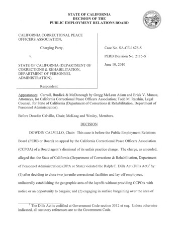
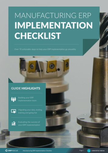
International Journal of Scientific & Engineering Research, Volume 9, Issue 6, June 2018ISSN 2229-5518145Design & Implementation of an IoT Based 3-AxisCNC VMCAmit Kumar NandiAbstract— Computer numerical control is a very broad term that encompasses a variety of types of machines— all with different sizes,shapes, and functions. But the easiest way to think about CNC is to simply understand that it’s all about using a computer as a means tocontrol a machine that carves useful objects from solid blocks of material. Our Project mainly deals with implementation of a desktop-sized3-Axis CNC machine and necessarily adding the functionality of controlling the machine from anywhere with an Internet Connection. Oneof the primary target of this project revolves around low-cost Printed Circuit Board (PCB) manufacturing and essentially making it availablefor and end user who can create their own custom PCBs without prior complicated knowledge of CNC milling and investing on costlymachines. The main motive behind wireless machine control from the internet is to create an ecosystem of these kind of connecteddevices which could act as a step ahead towards the goal of providing industry-grade solutions for total sales-cycle automation in the PCBmanufacturing industry all the way starting from order procurement to supply chain, manufacturing and delivery cycle automation.Distribution of these kind of devices to the engineering institutions could also be a venture to be worked upon as there is a need for makingcustom PCBs there. Apart from PCB manufacturing, robust solutions for customized wood and plastic surface engravings can also beprovided through this project. The Prototype Model is IoT based thus providing it a scalable architecture to use it from practically anywherewith an internet connection. This is a 350mm x 350mm CNC with a 250mm x 240mm work area, running on open source motion controlsoftware(GRBL). Even our Hardware is also mostly open source and thus comes the major cost cutting. This machine is made wholly fromlocally purchased items and can machine on wood, plastics, hard rubber, hard resin etc. The primary target is low-cost PCB manufacturing.Index Terms— CNC, Industrial Automation, PCB Manufacturing, IoT, Machining, Manufacturing, Control SoftwareIJSER—————————— ——————————1INT RO D UCTIONTheGross Value Added (GVA) from the Indianmanufacturing sector is estimated at 19,560 Crore INR inFY18. The sector’s contribution to the country’s GDP stoodat 16.51 per cent in 2017, which is set to increase in the nextupcoming quarters to around 20 percent because of theactive wave of manufacturing revitalization efforts taken bythe Indian Government, like Make in India etc. So, CNCmachines like ours is really a snug fit for the Indianmanufacturing sector, enabling low-cost engraving, facemilling possible and more reachable to the consumer andB2B sector as well. There is a huge need for in-houseprofessional manufacturing equipment to get end-to-endbenefits from the manufacturing sector boom that can bemade possible in the upcoming years.This paper is a step forward to the goal of makingconnected industrial systems for the Industry 4.0 revolutionthat is being seen worldwide. We want to achieve highprecision double sided PCB manufacturing with ourprototype machine while the prospect of Our fundamentalobjective lies in making low-cost manufacturing possible.This objective is followed by our long-term professionalgrade wood craving is also there. We’re Planning to addLaser Machining support as part of our future project. Asthe system can be presently controlled from a local Intranetwirelessly as of now, we want to scale it further to make adistributed model web application to make and connect anecosystem of multiple number of these-kind-of-devices. Thepossibilities are unlimited with this machine.2PROPOSED MODEL2.1 BRIEFFigure 1 Recent Indian Manufacturing Sector ScenarioThe prototype model has its base frame made out of 2020 Tslotted Aluminum Extrusions and L-Joints. The machinegives roughly about 80-85 Watts power with its 2000 rpmDC controlled spindle. It has lead screw and threaded rodmovement scheme with guiding smooth rods having radialgroove snap fit ball bearings for smooth operations alongall the 3 axes. The minimum lead pitch is0.8mm/revolution with a 2000 steps/revolution we have aresolution of 1600 for all the axes. Our rough machine sizeis about 430x430x330mm and work area is about270x170x65mm with 0.04mm positional accuracy. Our Zaxis gantry is 3d printed from scratch with dual guidingrods. The Z axis travel 4.8 cm with spindle bit mounted.We’re using 45 V-bit cutting tool for PCB engravingIJSER 2018http://www.ijser.org
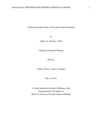
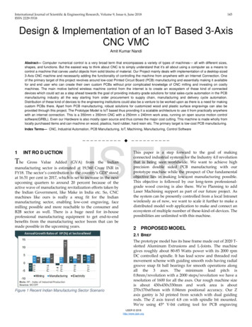
International Journal of Scientific & Engineering Research, Volume 9, Issue 6, June 2018ISSN 2229-5518purposes, it also supports 0.2mm to 1.8mm end mill bits.We’re using NEMA 23 Stepper motors with 3A max currentfor each axis main drive. The motors are driven by 2.5AA4988 drivers with 1/16th maximum micro-steppingresolution providing us the ultimate machining precision ata very economic cost. For the IoT (Internet of Things) part,we have made it possible to control the CNC router from aheadless display like a mobile / tablet screen (acting as ourHMI here) from anywhere with an Internet connection.We’re using a Raspberry Pi and a Router(security)arrangement connected to the internet and running awebserver to provide an interface for controlling our CNCwirelessly. We’re also planning to get hold of valuablemachine part insights like real time motor torque, currentdrawn, vibration, noise etc. and draw real time insights in aweb platform for better collaboration. Which is perhapscalled in the manufacturing sector as the Industrial IoT(INDUSTRY 4.0) or IIOT.146device for accurate and precise outputs. The Controllingcomputer can be a desktop sized PC or a palm sized mobilecomputing platform. The total power needed by the systemcan be provided easily with Li-Ion battery banks whichessentially makes the system wholly portable.2.4 CIRCUIT SCHEMATIC:2.2 MAIN COMPONENTS X, Y and Z axis mountings and gantry assembly.Electronic Components.Motors.Power Supply.IoT and networking equipment.CAD/CAM Design Software.Machine Control Software.IJSER2.3 FUNCTIONAL BLOCK-DIAGRAM:Figure 3: PROTEUS Simulation of 3-Axis CNC with Arduino asMCU.3. METHODOLOGY3.1 HARDWAREThe major hardware components used in the prototypemodel are:Figure 2 A Rough Functional Block Diagram of our 3Axis IoTCNC VMCIn the bock diagram described above, there is asynchronous link between the device running thewebserver and the device to be controlled. Moreover,closed loop control has been incorporated in the control NEMA 23 Stepper Motors555 air-cooled 2000rpm 12-24V spindle motor2020 Aluminum extrusionsThreaded rodLead ScrewGuiding Smooth RodsBall BearingsL-jointsMotor Shaft CouplersM5, M8, M3, M4 type machine head screws and boltsM3 T-NutsSize 2 and Size 4 Hex ScrewsArduino Nano (open-source board design)A4988 Stepper DriverArduino Nano compatible (3stepper 1dc) shield (opensource board design)Z-axis gantry mount and X, Y axis risers.Control Station Computer (Raspberry Pi / PC)IJSER 2018http://www.ijser.org
International Journal of Scientific & Engineering Research, Volume 9, Issue 6, June 2018ISSN 2229-5518 HMI station (Smartphone / tablet)Network Router12V/5A Switched Power supply (for machine only),12V/2A for Raspberry Pi and 5V/800mA for Router.Control Board Cooling Fan1473.4 A4988 STEPPER DRIVERThis is a DMOS Micro-stepping Driver with Translator andOvercurrent Protection. This stepper motor driver controlsone bipolar stepper motor at up to 2 A output currenthaving 1/16tm maximum micro-step resolution. The boardis 3.3v -5v logic tolerant.3.2 STEPPER MOTORSNEMA 23 standard bipolar stepper motors have been usedin the project for all the 3 axes. They provide 1.8 step-angle(200 steps/revolution) with each phase drawing 2.8A at2.5Volts, which is about 12Volts.It has 10N axial force and28N radial force at highest holding torque of 126 N-cm.These motors are 24 Volts tolerant having 4 wire switchingleads and 1/8th micro-stepping support.Figure 6: A4988 pinout3.5 THE MAIN MECHANICAL BUILDING BLOCK—2020ALUMINUM EXTRUSIONSIJSERThese are aluminum T-slotted profiles with considerabletensile strength which forms the main building blocks ofthe CNC machine along with L-Joints. The main feature ofthese profiles is their rigidity.Figure 4 NEMA 23 Specs & drawing3.3 SPINDLE MOTORFor Spindle motor of the Z-axis, a 555-DC motor is used. Itis a 12V/1200mA low speed high torque motor withmaximum load condition speed is 2000rpm and no-loadspeed being 6000rpm. The Speed control is done by an IRF540 Power MOSFET and 555 timer IC for PWM switchinginbuilt within the motor shield.Figure 5: 555 DC motor Specs & DrawingIJSER 2018http://www.ijser.org
International Journal of Scientific & Engineering Research, Volume 9, Issue 6, June 2018ISSN 2229-5518148Figure 7: 2020 T-slot profile Drawing (sideview)Figure 9 isometric Projection of 3-axis CNC VMC3.6. MACHINE DESIGN/ORIGINAL DRAFTS (TOP VIEW ANDISOMETRIC PROJECTION)3.7 CONTROL AND DESIGN SOFTWAREIJSERFor all the design, modeling, G-Code generation andmachining simulation needs, AutoDesk Fusion 360software’s 3-year Free Student License is being used.Though there are lot of other proprietary and open sourceapplications available in the market for G-Code/Toolpathgeneration, we found AutoDesk’s solutions to be best fittedfor our project.For machine Control software, the GRBL(v0.9)* OpenSource Firmware for the Atmel ATmega microcontrollers ischosen. It is a community-based, free and open source,embedded, high-performance G-Code-parser and CNCmilling contour controller written in hardware-optimized Cthat runs on any ATMega Based MCUs (Arduino in ourproject). The firmware/driver runs on the Microcontrollerwhile the software to control that firmware runs on any x86or GNU based computing platform.*Grbl is free software, released under the GNU LGPLv3license.**GitHub Repository link: https://github.com/grbl/grbl.The Prototype machine can only interpret G-Codes, so anymodel which needs to be milled must be converted to itsequivalent G-Codes by a process called toolpathgeneration. Softwares like ArtCAM, PyCAM (open-source)are used to generate G-Code from CAD model files. AnExample Model and its equivalent G-Codes with theirrelevant meanings are given below:Figure 8 TopView of IoT Based CNC VMCIJSER 2018http://www.ijser.org
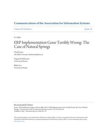
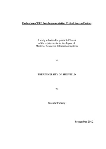
International Journal of Scientific & Engineering Research, Volume 9, Issue 6, June 2018ISSN 2229-5518149The below two graphs describes the change in terms ofvibration v/s time of the machine at 1second interval.IJSERPhotograph 1 Example Model with corresponding G-Codes and theirworkingFigure 10: Vibration output analysis from all the 3 axes4RESULTS AND DISCUSSIONThe outcome of the project is pretty impressive as themachine can draw curved points as small as 0.6mmdiameter. With a 12V/5A total power consumption, thismachine can bear tool axis torque of up to 24 N-cm. 0.5mmPCB channel widths is cleanly milled with this machine.The graph below describes the overall normalized noiselevel from the machine at 10cm radius.Though the Z-axis needs a bit of more stability in terms ofmechanical fittings. We are using closed loop steppercontrol, so machine homing/zeroing is steady, although thepositional control accuracy needs to be increased.At 2000rpm, 60% feed rate and 34% plunge rate, a 30mm x30mm work-area, 28-lead channel engrave-milling requiredaround 4 minutes time, which is more than expected fromthe 85watts effective power the machine.Vector images can also be engraved in hard TPU plasticswith 2.5D raster milling techniques.4.1 NOISE AND VIBRATION ANALYSIS OF THE MACHINE:The Bosch iNVH Andoid App is used to measure andanalyze vibration and noise level of the machine in steadystate running condition. The outputs are satisfactory for amachine of this size and vibrations can be minimized to agreater extent by using gantry mufflers and high-qualitystepper motor coupling bearings. Further noise reductioncan be done by using pulley sliders in place of ball screws.Figure 11 Normalized Noise LevelsAs it can be observed from the above noise data the levelsdo not reach above 72dB even during the most challengingmachining operations. The noise testing has been done onmobile device microphone having 10KHz unidirectionalresolution which can prove to be a major bottleneck whilemeasuring the noise output. Use of condenser microphonewith relatively higher omnidirectional resolution can solvethis problem.The vibrational outputs are measured on a Bosch BM421gyro accelerometer sensor having 12-bit digital outputresolution and accuracy of measurement in terms of 2g.IJSER 2018http://www.ijser.org
International Journal of Scientific & Engineering Research, Volume 9, Issue 6, June 2018ISSN 2229-5518The graph below describes the change in terms ofinstantaneous noise level [dB(A)] v/s time(seconds) of themachine at 1s interval.150Due to software limitations spindle control can be handledup to 2000rpm only. An added step of precision can beadded to the machine by introducing positive and negativelimit switches for all the three axes.Essentially, addition of an integrated application layer toour product will help it to achieve supply chain to deliverycycle automation especially in the PCB manufacturingindustry. Which will eventually cut down sales overheadsand maximize production. This project is published in theopen-source makers’ community called ‘Hackster’ underGNU LGPL open source license having 50 communityrespects in under a month.URL: c-vmc4817baFigure 12: Noise Output AnalysisBelow are some photographs taken on copper clad boardsand TPU plastics demonstrating finished end millingprocesses:IJSERPhotograph 2: Final CNC Machine.Photograph 4: End milling of PCBs on dual-sided copper cladboard done on our 3 axis CNC.Photograph 3 :PCB with 0.8mm channes widths of an ATmega328p SMD chip.Photograph 5: Precision Micro Lettering witch each letterthhaving dimensions of the order of 1/8 of an inch i.e. 3.1mmroughly. [thumb and index finger for scaling]High precision circular raster milling can also be achievedwith our machine in order to engrave high resolutionimages. Point to point milling of considerable accuracy canbe obtained from the machine.IJSER 2018http://www.ijser.org
International Journal of Scientific & Engineering Research, Volume 9, Issue 6, June 2018ISSN 2229-5518 151PCB manufacturing using precision milling techniqueat incredibly low cost.Z-axis tool can be fitted with a spindle motor or a Laserdiode module (for laser engraving).The whole system is 12V operable and 24 volts tolerantfor industry standard DC supply scenarios.High torque steppers and spindle perfect for low tomedium speed milling operations.Hard Rubber, Soft Metal, Wood, PVC, PET and otherplastics can be milled and engraved upon.Y-Axis workpiece supports 2.8kg maximum loadwithout noticeable vibrationsguiding rods for smooth and strong X to Z axis gantrycoupling.6 LIMITATIONSIJSERPhotograph 5: Circular Rastering of a 400x400px. resolutionimage (top)Photograph 6: Point to Point milling of 3rd Reich Emblem(middle) and an engraved signature of great poet RabindranathTagore. (bottom)4.2 GLOBAL COMPETITION:hat we have figured out after a brief market study aboutour product is that, there are currently a lot of companieswho are pushing this idea of low-cost machining intoreality. Some of the renowned companies making productssomewhat similar in functionality to ours are as follows:Carbide 3D LLC – The ‘Shapeoko’ Milling Machine,specially designed to mill PCBsX-Carve – Open Source Hardware projectPocketNC – An US based 2012 crowdfunded startupproviding professional 5-Axis CNC machines that fits in adesktop table and can mill on 4140 AluminumIsel AG – A German company providing end to enddesktop sized CNC machines and OEM user replaceablepart manufacturing for their machines.5 ADVANTAGESSome of the major advantages of our CNC machine are asfollows: With 85Watts maximum power output from all the 3 axes,this CNC machine cannot mill on alloy steel or hard metals.The Depth of Cut (DOC) is also limited to 3mm maximumfor 2000rpm spindle motor. Greater DOC ( 1cm) can beachieved with higher speed spindle motor(12000rpm)which we aren’t able to use in order to keep the design andprototyping costs low. The steppers have 200steps/revsresolution which gives 0.8mm minimum pitch and 0.06mmpositional accuracy. With high quality, imported(2000steps/revs) motors, we can achieve even greaterpositional accuracy in the terms of 0.01mm.Low-Cost 3-axis CNC Automation.Low-Maintenance Design.7 CONCLUSIONSOur project prototype described in this paper is a verygeneric approach to low-cost, affordable and connectedmachining centers. With the advent of the recentautomation trend-INDUSTRY 4.0, we need more and moreof these kind of machining products for specific industrialneeds which will provide a connected ecosystem for themachining needs and serve as a platform for generation ofhuge manufacturing insights through IoT based dataaggregation in the Cloud.ACKNOWLEDGEMENTThe completion of any project brings with it a sense ofsatisfaction, but it is never complete without thanking thosepeople who made it possible and whose constant supporthas crowned our efforts with success.I would like to thank Prof (Dr.) Anil Kumar Bag of HeritageInstitute of Technology, Kolkata for letting us form a groupand carry out the project and also for allowing us to use thecollege infrastructure to complete the project and test it. Wehereby thank our respected Head of the Dept. of AppliedElectronics & Instrumentation Dept., Prof (Dr.) MadhurimaChattopadhyay for providing constant inspiration.I also would like to thank all the faculty& staff members ofApplied Electronics & Instrumentation Dept. for providingIJSER 2018http://www.ijser.org
International Journal of Scientific & Engineering Research, Volume 9, Issue 6, June 2018ISSN 2229-5518us with the required facilities and supports towards thecompletion of the project.*All the photographs given in this project has been taken onauthors’ personal mobile phone camera.Amit Kumar Nandi,12614005010,B.Tech 4th Year 8th Semester,Applied Electronics and Instrumentation Engg. Dept.,Heritage Institute of Technology, ,https://git.ng.bluemix.net/amitnandileoEmail: bigwiz@tuta.ioREFERENCES152[1] Mike Lynch, "Key CNC Concept #1—TheFundamentals Of CNC", Modern Machine Shop, 4January 1997.[2] Grace-flood, Liam (2017-11-10). "Goliath Represents aNew Breed of CNC Machine".[3] "Multi Spindle Machines - An In DepthOverview". Davenport Machine. Retrieved 2017-08-25.[4] "Machining Types - Parts Badger". Parts Badger.Retrieved 2017-07-07.[5] Autor, David H. (2015). "Why Are There Still So ManyJobs? The History and Future of WorkplaceAutomation". Journal of Economic Perspectives[6] Frohm, Jorgen (2008), Levels of Automation , ISBN 978-91-7385-055-1.[7] The History of Fanuc". EdTech. MCC. Retrieved 29October 2017IJSERIJSER 2018http://www.ijser.org
CAD/CAM Design Software. Machine Control Software. 2.3 F UNCTIONAL B LOCK-DIAGRAM: Figure 2 A Rough Functional Block Diagram of our 3Axis IoT CNC VMC . In the bock diagramdescribed above, there is a synchronous link between the device running the webserver and the device to be , controlled. Moreover