Transcription
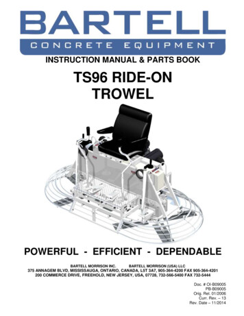
INSTRUCTION MANUAL & PARTS BOOKTS96 RIDE-ONTROWELPOWERFUL - EFFICIENT - DEPENDABLEBARTELL MORRISON INC.BARTELL MORRISON (USA) LLC375 ANNAGEM BLVD, MISSISSAUGA, ONTARIO, CANADA, L5T 3A7, 905-364-4200 FAX 905-364-4201200 COMMERCE DRIVE, FREEHOLD, NEW JERSEY, USA, 07728, 732-566-5400 FAX 732-5444Doc. # OI-B09005PB-B09005Orig. Rel. 01/2006Curr. Rev. – 13Rev. Date – 11/2014
TS96 RIDE-ON TROWEL INSTRUCTION MANUALSAFETY PRECAUTIONS!DANGEREXPLOSION HAZARDNever operate the machine in anexplosiveatmosphere,nearcombustible materials or whereventilation does not clear exhaustfumes.!WARNINGBURN HAZARDNever come into contact with theengine or muffler when engine isoperating or shortly after it isturned off. Serious burns mayoccur.!WARNINGROTATING HAZARDNever place hands or feet insidesafety guard rings. Serious injurywill result from contact with rotatingblades.!CAUTIONMOVING PARTSBefore starting the machine ensurethat all guards and safety devicesare in place and functioningproperly.! ATTENTIONREAD OWNERS MANUALRead and understand operator'smanual before using this machine.Failure to follow operatinginstructions could result in seriousinjury or death.BARTELL MORRISON INC.BARTELL MORRISON (USA) LLC375 ANNAGEM BLVD, MISSISSAUGA, ONTARIO, CANADA, L5T 3A7, 905-364-4200 FAX 905-364-4201200 COMMERCE DRIVE, FREEHOLD, NEW JERSEY, USA, 07728, 732-566-5400 FAX 732-566-5444-2-Created: 01/06Revised: 06/14
TS96 RIDE-ON TROWEL INSTRUCTION MANUALTABLE OF CONTENTSQUALITY ASSURANCE/MACHINE BREAK-IN .4RIDE-ON POWER TROWEL WARRANTY .5MAINTENANCE RECORD .6ROUTINE SERVICE INTERVALS .7FOREWORD .9SAFETY PRECAUTIONS.9ASSEMBLY INSTRUCTIONS .91. BATTERY .92. STEERING HANDLE ASSEMBLY .93. PITCH CONTROL ASSEMBLY (FIGURE 1) .94. SEAT ASSEMBLY .105. TRANSPORTER ASSEMBLY .10OPERATING INSTRUCTIONS .101. STARTING PROCEDURES - WARM TEMPERATURES .102. STARTING PROCEDURES - COLD TEMPERATURES .103. STOPPING PROCEDURES .104. STEERING (FIGURE 2) .105. FLOAT/TROWEL PITCH SETTING .116. BLADE SYNCHRONIZATION (FIGURE 3) .117. TRANSPORTER USE .11MAINTENANCE INSTRUCTIONS .111. GENERAL .112. AIR CLEANER.113. SPARK PLUG.114. BELT CHANGE PROCEDURE .125. BELT TENSIONING SPECIFICATION (FIGURE 4).12LUBRICATION .121. ENGINE OIL .122. SPIDER PLATE .123. GEARBOX.124. GEARBOX OIL CHANGE .125. GREASE FITTINGS .12ENGINE OIL SPECIFICATION .12TROWEL ARM ADJUSTMENT FIXTURE .131. ADJUSTMENT PROCEDURE .13ASSEMBLY DRAWINGS AND PARTS LIST .151. CHASSIS ASSEMBLY (FIGURE 1) .16CHASSIS PARTS LIST .172. POWERPLANT ASSEMBLY (FIGURE 2) .20POWERPANT PARTS LIST .213. DRIVE TRAIN ASSEMBLY (FIGURE 3) .22DRIVE TRAIN PARTS LIST.234. STEERING ASSEMBLY (FIGURE 4) .26STEERING PARTS LIST .275. GEARBOX ASSEMBLY (FIGURE 5).28GEARBOX PARTS LIST .296. SPIDER PLATE ASSEMBLY (FIGURE 6) / PRESSURE PLATE ASSEMBLY (FIGURE 7) .30SPIDER PLATE ASSEMBLY / PRESSURE PLATE ASSEMBLY PARTS LIST .317. PITCH CONTROL HANDLE (FIGURE 8) .32PITCH CONTROL PARTS LIST .338. RETARDANT SPRAY SYSTEM (FIGURE 9) .34RETARDANT SPRAY SYSTEM PARTS LIST .359. TROWEL BLADE ASSEMBLY (FIGURE 10).36TROWEL BLADE PARTS LIST .3610. TRANSPORTER ASSEMBLY (FIGURE 11) .37TRANSPORTER PARTS LIST .37TROUBLESHOOTING .38SPECIFICATIONS .39COMPANY INFORMATION .40NOTES.41BARTELL MORRISON INC.BARTELL MORRISON (USA) LLC375 ANNAGEM BLVD, MISSISSAUGA, ONTARIO, CANADA, L5T 3A7, 905-364-4200 FAX 905-364-4201200 COMMERCE DRIVE, FREEHOLD, NEW JERSEY, USA, 07728, 732-566-5400 FAX 732-566-5444-3-Created: 01/06Revised: 06/14
TS96 RIDE-ON TROWEL INSTRUCTION MANUALQUALITY ASSURANCE / MACHINE BREAK INThe Bartell Ride-on Trowel is the product of extensive engineering development designed to givelong life and unmatched performance. Once machines are fully assembled, a run-in test isperformed to ensure quality standards of the highest level. A series of operational tests areconducted on concrete, incorporating a phase of operations at 1/2 to ¾ throttle for a minimum of20 minutes and a final run phase at full throttle for a minimum of 25 minutes.You can help ensure that your ride-on trowel will perform at top levels by observing a simplerouting on first use. Consider that your new Ride-on Trowel is like a new car. Just as you wouldbreak in a new car to the road or any new machine to the job, you should start gradually andbuild up to full use. Learn what your machine can do and how it will respond. Refer to theengine manufacturer’s manual for run-in times. Full throttle and control may be used after thistime period, as allowed by material. This will serve to further break in the machine on yourspecific application, as well as provide you with additional practice using the machine.We thank you for the confidence you have placed in us by purchasing a Bartell Ride-on Troweland wish you many years of satisfied use.BARTELL MORRISON INC.BARTELL MORRISON (USA) LLC375 ANNAGEM BLVD, MISSISSAUGA, ONTARIO, CANADA, L5T 3A7, 905-364-4200 FAX 905-364-4201200 COMMERCE DRIVE, FREEHOLD, NEW JERSEY, USA, 07728, 732-566-5400 FAX 732-566-5444-4-Created: 01/06Revised: 06/14
TS96 RIDE-ON TROWEL INSTRUCTION MANUALRIDE-ON POWER TROWEL WARRANTYBartell Morrison Inc. agrees to furnish without charge, F.O.B. our plant, a replacement forany part or portion thereof, comprising the drive train of the Bartell Ride-on Power Trowel,consisting of the drive shaft assembly and the gear case assemblies, save and exceptdrive belts, power units, and/or bearing or electrical controls which prove upon ourexamination, to be defective in either material or workmanship within a period of twelve(12) months from date of purchase, provided that notice of such defective part or portionthereof is given to Bartell Morrison Inc. within the twelve month warranty period. Nofurther or other guarantee or warranty expressed or implied in connection with the sale ofthe Ride-on Power Trowel is given and our sole liability consists in replacing defectiveparts or portions thereof. We shall not be responsible for any special, indirect orconsequential damages arising in any manner whatsoever.This guarantee is for the sole benefit of the original purchaser as end user. Ourresponsibility under this guarantee ends in the case the original purchaser transfersownership of the Ride-on Power Trowel, makes any changes or adds any parts or devicesnot of our manufacture to the Ride-On Power Trowel.BARTELL MORRISON INC.BARTELL MORRISON (USA) LLC375 ANNAGEM BLVD, MISSISSAUGA, ONTARIO, CANADA, L5T 3A7, 905-364-4200 FAX 905-364-4201200 COMMERCE DRIVE, FREEHOLD, NEW JERSEY, USA, 07728, 732-566-5400 FAX 732-566-5444-5-Created: 01/06Revised: 06/14
TS96 RIDE-ON TROWEL INSTRUCTION MANUALMAINTENANCE RECORDPREVENTATIVE MAINTENANCE AND ROUTINE SERVICE PLANThis Bartell ride-on power trowel has been assembled with care and will provide years of service. Preventativemaintenance and routine service are essential to the long life of your Bartell ride-on power trowel. Your dealer isinterested in your new trowel and has the desire to help you get the most value from it. After reading through thismanual thoroughly you will find that you can do some of the regular maintenance yourself. However, when in needof parts or major service be sure to see your Bartell dealer. For your convenience we have provided this space torecord relevant data about your ride-on Trowel. When in need of parts or service be prepared to provide your trowelserial number. Locate the serial number now and record in the space below.Date Purchased:Type of Machine:Dealer Name:Model:Dealer Phone:Serial Number:REPLACEMENT PARTS USEDPART NO.QUANTITYCOSTMAINTENANCE LOGDATEDATEOPERATIONBARTELL MORRISON INC.BARTELL MORRISON (USA) LLC375 ANNAGEM BLVD, MISSISSAUGA, ONTARIO, CANADA, L5T 3A7, 905-364-4200 FAX 905-364-4201200 COMMERCE DRIVE, FREEHOLD, NEW JERSEY, USA, 07728, 732-566-5400 FAX 732-566-5444-6-Created: 01/06Revised: 06/14
TS96 RIDE-ON TROWEL INSTRUCTION MANUALRoutine ServiceIntervalsEachuseAfter 1.5 Each 3months monthsoror50 hrs 100 hrsEach 6monthsor200 hrsEach 9 Each 12months monthsoror300 hrs 400 hrsGeneral Inspection:Operation of lightsBatteryCheckClean & CheckRechargeReplaceCheckCheckCheck operationGuardsWarning stickersTest run:ooooooooooooo2 ooooo2 yrsooooooooooooooo2 yrsoooooooControls:Dead-man switch operationThrottle pedal operationSteering linkagesPitch control leversJoystick controlsHydraulic eCheckCheck levelsCheck hosesReplace hosesooooAs req’doooEngine:Fuel pipes & clampsEngine oilEngine oil filterOil coolerCooling FinsAir cleanerAir Intake LineFan BeltValve clearanceFuel filterFuel TankFuel Injection NozzlesFuel Injection TimerInjection PumpEngine wiringCheckReplaceCheck LevelChangeReplaceCleanCleanCheck - cleanReplaceCheckReplaceCheck tightnessReplaceCheck-adjustCheck & CleanReplaceCleanCheck pressureCheckCheckCheckooooooooooooooooo2 yrso500 hrsooo500 hrs500 hrs500 hrs500 hrsoContinued on next page BARTELL MORRISON INC.BARTELL MORRISON (USA) LLC375 ANNAGEM BLVD, MISSISSAUGA, ONTARIO, CANADA, L5T 3A7, 905-364-4200 FAX 905-364-4201200 COMMERCE DRIVE, FREEHOLD, NEW JERSEY, USA, 07728, 732-566-5400 FAX 732-566-5444-7-Created: 01/06Revised: 06/14
TS96 RIDE-ON TROWEL INSTRUCTION MANUALRoutine Service Intervals- Continued -EachuseAfter 1.5 Each 3months monthsoror50 hrs 100 hrsEach 6monthsor200 hrsEach 9 Each 12months monthsoror300 hrs 400 hrsDrive Train:BearingsUniversal couplingsBelt tension / ConditionClutch / Pulley operationLH spider plate ass’mRH spider plate ooooooooooooooooooooooooooooooooGearboxes:LH Gearbox oilRH Gearbox oilGearbox breathersCheck LevelChangeCheck LevelChangeCheck operationRetardant Spray System:Water pump operationCheckSpray nozzlesCleanRetardant FluidCheck levelsoooooDue to the nature and environment of use, power trowels are exposed to severe operating conditions.Some general maintenance guidelines will extend the useful life of your trowel. The initial service for your power trowel should be performed after 25 hours of use, at which time your mechanic(or authorized repair shop) should complete all of the recommended checks in the schedule above. The charton page 6 (six) is handy for keeping a record of the maintenance performed and the parts used for servicing yourtrowel.Regular service according to the schedule above will prolong the life of the power trowel and prevent expensiverepairs.Keeping your power trowel clean and free from concrete residue is the single most important regularmaintenance operation, over and above the checks in the service schedule above, that can be performed.Components such as oil seals, belts, drive line parts and bearings are prone to premature wear from exposure toconcrete residue. Using a spray-on non-stick coating on your power trowel before each use will make clean-upafter use easy and extend the time between replacement of most of the wearing components of the machine.After each use your power trowel should be cleaned to remove any concrete residue from the undercarriage andsurrounding components. Use of a power washer will make clean up quick and easy, especially if a non-stickcoating was applied prior to use.In the Service Schedule above, items that should be checked, replaced or adjusted are indicated by “o” in theappropriate column. Not all power trowel models include the same features and options and as such not allservice operations may have to be performed. For ease of recording place a checkmark ( ) through the “o”when the item is complete. If an item is not required or not completed place an “x” through the “o” in the box.For all fuel-line powered trowels the governed speed of the engine is 2000 to 3600 rpm. See enginemanufacturer’s manual for exact specifications. Care should be used when making any adjustments to thepower trowel not to change the governed speed. Increasing the governed speed of the engine may lead topremature failure and void the manufacturer’s warranty.Failure to have your power trowel regularly serviced and properly maintained in accordance with themanufacturer’s instructions will lead to premature failure and void the warranty.BARTELL MORRISON INC.BARTELL MORRISON (USA) LLC375 ANNAGEM BLVD, MISSISSAUGA, ONTARIO, CANADA, L5T 3A7, 905-364-4200 FAX 905-364-4201200 COMMERCE DRIVE, FREEHOLD, NEW JERSEY, USA, 07728, 732-566-5400 FAX 732-566-5444-8-Created: 01/06Revised: 06/14
TS96 RIDE-ON TROWEL INSTRUCTION MANUALFOREWORDASSEMBLY INSTRUCTIONSIt is important that the following be read carefully inorder that the operational performance of the BartellRIDE-ON Trowel be fully understood.Propermaintenance procedures will ensure long life and topperformance of the unit.Your new Bartell Ride-On Trowel has been shipped to youpartially disassembled. To prepare for operation use thefollowing instructions:SAFETY PRECAUTIONS Always keep unauthorized, inexperienced, untrainedpeople away from this machine.Rotating and moving parts will cause injury ifcontacted. Make sure guards are in place. Keephands and feet away from moving parts.Fuel the machine only when the engine is stopped,using all necessary safety precautions.The engine must always be stopped beforeattempting any repair or adjustments. Ignition keyshould be off. Danger: Never operate the machinein an explosive atmosphere, near combustiblematerials or where ventilation does not clearexhaust fumes. Repair fuel leaks immediately.Refer to your engine owner’s manual for moresafety instructions.Be careful not to come in contact with the mufflerwhen the engine is hot, serious burns may result!Always operate the machine in a seated position tomaintain machine balance.The transporter is designed for moving the unitaround the job site only. It is not to be used fortowing the Ride-On unit off-site.When starting the trowel, do not exceed the 1/4throttle position as recommended. A higher settingcould cause the centrifugal clutch to engage,activation the trowel blades.Be careful with the trowel around stub pipes or otherobstructions on the floor. Should the machinecatch, or hit such an obstruction, serious damagemay result to the machine, or operator may bethrown from the machine.Excess surface water may result in sudden loss ofcontrol of steering.Disconnect battery before attempting any electricalmaintenance.Ensure that the electrical dead-man switch, locatedunder the left foot pedal is operating. Placing yourleft foot flat on the pedal will engage the safetyswitch. Removing you foot from the pedal willdisengage the safety switch and stop the engine.The engine will not start unless the safety switch isdepressed. This safety feature must be used asdesigned.1. BATTERY – SHIPPED DRY – NO ACIDConnect and secure the battery cables beforeattempting starting procedures.2. STEERING HANDLE ASSEMBLYThe steering handles are shipped ready to connect.Position the handles over the handle sleeves so thatthe set-screws (2 per handle) are lined up with thetapped holes on the sleeves. Tighten the set-screwsand test the mobility of the handles.3. PITCH CONTROL ASSEMBLYFigure 1a.Bolt pitch control tube (C) to pitch control bracket (D) withbolts provided. Put cable end (E) through yoke arm (F)and secure with nylon insert locknut (G). For proper cableadjustment, turn crank (A) counter-clockwise to the stopposition. Tighten nut (G) until all slack in the cable isremoved. If more than 2 or 3 threads show through thenut, it should be turned back and the guide screw (B)moved to the next lower hole. Tension in the cable shouldthen be readjusted. After adjusting tension, turn handcrank full clockwise (ABOUT 24 TURNS) and check forclearance between the yoke arm (F) and the gear box atpoint (H). There should be enough space to pass abusiness card through but not more than 1/8 inch.BARTELL MORRISON INC.BARTELL MORRISON (USA) LLC375 ANNAGEM BLVD, MISSISSAUGA, ONTARIO, CANADA, L5T 3A7, 905-364-4200 FAX 905-364-4201200 COMMERCE DRIVE, FREEHOLD, NEW JERSEY, USA, 07728, 732-566-5400 FAX 732-566-5444-9-Created: 01/06Revised: 06/14
TS96 RIDE-ON TROWEL INSTRUCTION MANUAL4. SEAT ASSEMBLYRemove protective wrapping from seat. The seat isnow ready to secure to the frame using includedwashers and hex nuts. If the seat adjuster isordered, the slider bars must be positioned betweenthe seat and the frame using included screws tosecure the seat to the sliders, and then securing thesliders to the frame as indicated above.5. TRANSPORTER ASSEMBLYThe components of the are detailed in the partsdrawing within this manual (pg. 34). The assemblyof the transporter consists of only the wheel and pin,and the main transporter body. This transporter isshipped with very little assembly required.3. TO STOP ENGINEa) Bring throttle to low idle, wait a few seconds.b) Remove left foot from dead-man safety switch.c) Turn off ignition key.4. STEERINGGuiding the machine on the slab is quite simple butdoes require some familiarity before actually workingwith the machine. The controls respond as shown infigure 2a below. Test the machine on a finishedsection of the floor, with the blades in a flat position,and the engine at a low revolution to gain thenecessary feel for the steering.CAUTION:The transporter is designed to be used on thejob site only. Do not use the transporter to towthe machine off-site.OPERATING INSTRUCTIONS1. STARTING PROCEDURES* WARM TEMPERATURESa) Prior to starting the trowel, check the engine andgearbox oil levels. Be sure the fuel tank is full.Fuel is not shipped with the unit. Beforeattempting to start, fill the fuel tank. Checkengine and gearbox oil levels. WARRANTY ISVOID IF RUN WITHOUT OIL. Fill tank withsafety approved fuel containers. DO NOT MIXOIL WITH FUEL.b) Maintain left foot pressure on the dead-mansafety switch. Engine will disengage and stop ifsafety switch is released. Do not tape, tie-down,or otherwise attempt to bypass safety device.c) Turn ignition key all the way. Allow engine towarm up before proceeding with full troweloperation.2. STARTING PROCEDURES* COLD TEMPERATURESFollow same procedure as above but allow for alonger warm up period 3-5 min. (In cold weather oilis much heavier to move. Extra time is required toheat the oil.)Figure 2a.For straight line movement, move both handles as one inthe direction you wish to travel. Move the handles inopposite directions to produce rotation on the machinesaxis. Left handle forward, right handle backward forclockwise rotation. Left handle backward, right handleforward, for counter-clockwise rotation. Sideways directionis achieved by sideways movement of the right handle inthe required direction of travel.WARNING:SERIOUS INJURY OR PROPERTY DAMAGE MAYRESULT DUE TO TEMPORARY LOSS OFCONTROL IF OPERATED WITH FRESH WATERON THE CONCRETE SURFACE.BARTELL MORRISON INC.BARTELL MORRISON (USA) LLC375 ANNAGEM BLVD, MISSISSAUGA, ONTARIO, CANADA, L5T 3A7, 905-364-4200 FAX 905-364-4201200 COMMERCE DRIVE, FREEHOLD, NEW JERSEY, USA, 07728, 732-566-5400 FAX 732-566-5444- 10 -Created: 01/06Revised: 06/14
TS96 RIDE-ON TROWEL INSTRUCTION MANUAL5. FLOAT/TROWEL PITCH SETTINGOnce you are familiar with the steering functions ona flat floor, you are ready to combine the steeringwith float/trowel pitch settings to produce the finishyou require. The pitch adjustment feature of theRide-on Trowel permits quick and accurate pitchchanges of the finishing/float blades, without havingto stop the machine. Turning the adjustment crankhandle at the end of the pitch control tubes enablesyou to change the pitch whenever necessary toallow for varying conditions over the slap surface.Each spider plate is adjusted independently. Thepitch setting will affect the steering of your unit.Experiment with the settings as you test drive soyou will know what to expect.CAUTION:Do not let the machine stand in one spot on thesoft cement; This may place unnecessary strainon the clutch to break it free of the cement. If theunit has been sitting for any length of time,break it free from the concrete before attemptingoperation.CAUTION:When finishing concrete above grade, erect asituation barrier along the edge of the slab as aprotective measure. The barrier should be suchthat it will stop the trowel from riding over theedge of the slab in case of loss of control.6.BLADE SYNCHRONIZATION(SPECIALLY MODIFIED UNITS ONLY)7. TRANSPORTER USECAUTION:The transporter is designed to be used on the jobsite only, Do not use it to tow the machine off-site.The transporter has pick-up brackets located on the insideof the wheels which should be positioned under the pickup points on the frame. Before connection, the handle willbe pointing upwards at approximately a 45 degree angle.Pull the handle down, engaging the transporter andsecure the bracket and transporter to the frame by lockingthe handle bracket in the frame lock by means of the hitchpin. Using the handle as a lever, the ride-on may now bemoved. To disconnect the transporter, follow the abovesteps in reverse.MAINTENANCE INSTRUCTIONS1. GENERAL Keep engine oil clean. Change according toengine manufacturer’s specifications. Maintain the oil levels in the engine and gearboxassemblies. Change as required. Use only clean fuel in the engine. Check for loose nuts and bolts on the trowel andtighten as necessary. Check “V” belts for wear, replace if worn. Grease all fittings daily. See diagram. Clean the unit after every use to preventhardening of sludge. Hard concrete is very difficultto remove, greatly increases weight and reducesefficient subsequent operation of unit. Check clutch linings regularly for wear. Liningsshould be changed when ¾ worn. Do not allowmetal to metal contact as this will damage theclutch drum. (New lining is 8mm.)2. AIR CLEANERMaintaining a clean engine will extend engine life.Keep air filter clean at all times. Clean air filter usingthe recommended solvent daily. See engine manualfor proper cleaning procedure. Let the filter dry beforereinstalling.Figure 3a.3. SPARK PLUGCheck and clean spark plugs regularly. A fouled, dirtyspark plug caused hard starting and poor engineperformance. Set spark plug gap to recommendedclearance. Refer to engine manual.To avoid blades hitting, make sure spider plates arepositioned as shown with respect to each other afterperforming any maintenance.BARTELL MORRISON INC.BARTELL MORRISON (USA) LLC375 ANNAGEM BLVD, MISSISSAUGA, ONTARIO, CANADA, L5T 3A7, 905-364-4200 FAX 905-364-4201200 COMMERCE DRIVE, FREEHOLD, NEW JERSEY, USA, 07728, 732-566-5400 FAX 732-566-5444- 11 -Created: 01/06Revised: 06/14
TS96 RIDE-ON TROWEL INSTRUCTION MANUAL4. BELT CHANGE PROCEDURERemove belt cover from the machine to expose thedrive components. To change the primary (CVT)drive belt, the driven pulley width can be openedmanually using a M6-1.0 screw with 30 to 35mmlong thread inserted into the screw hole at position11 marked on the face of the driven pulley. The beltcan then be slipped off the driven pulley.5. BELT TENSIONING SPECIFICATIONSNOTE:Belts may become slightly loose after the firstfew hours of operation. It is important to retension the belts and use the table given asreference.Belt lbs/kg)8.65/219.50.135/3.43/1.43. GEARBOXCheck the oil level sight plugs on both gearboxes dailyto ensure the oil is half way on the site glass. Top upwith Chevron HiPerSYN ISO 320 gear oil only.Gearbox capacity on the TS96 is 67oz./2000ml.4. TO CHANGE GEARBOX OILPlace a pan beneath the drain plug to catch the oil.Remove the drain plug and the filler plug from thegearbox. After the oil has drained completely, replacethe drain plug and tighten. Fill the gearbox through thefiller plug with 67oz./2000ml of Chevron HiPerSYNISO 320 oil or equivalent gear oil. Replace the fillerplug and tighten.5. GREASE FITTINGSThere are 12 bearings in total. Grease all bearings toensure adequate supply of lubricant. They are locatedabove the gearboxes (2 per gearbox), 4 located in thesecondary drive system, and 4 in the steeringlinkages.The primary belt drive uses the CVT(ContinuouslyVariableTransmission)technology and does not have any tensioningrequirements.LUBRICATION1. ENGINE OILThe long life and successful operation of any pieceof machinery is dependent on frequent and thoroughlubrication.Before using the trowel, always
TS96 RIDE-ON TROWEL POWERFUL - EFFICIENT - DEPENDABLE . TS96 RIDE-ON TROWEL INSTRUCTION MANUAL BARTELL MORRISON INC. BARTELL MORRISON (USA) LLC - 375 ANNAGEM BLVD, MISSISSAUGA, ONTARIO, CANADA, L5T 3A7, 905-364-4200 FAX 905-364-4201 . on page 6 (six) is handy for keeping a record of the maintenance performed and the parts used for servicing .


