Transcription
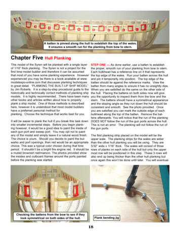
A batten is pinned along the hull to establish the top of the wales.It ensures a smooth run for the planking from bow to stern.Chapter FiveHull PlankingThis model of the Syren will be planked with a single layerof 1/16” thick planking. The Syren is not a project for thefirst time model builder and therefore it can be assumedthat most of you have some planking experience. Howeverexperienced you may be there is a book available at www.modelexpo-online.com that discusses planking techniquesin great detail. “PLANKING THE BUILT-UP SHIP MODEL”by Jim Roberts. It is a step-by-step procedural guide to thehistorically and technically correct methods of planking shipmodels. It is highly recommended. There have been manyother books and articles written about how to properlyplank a ship model. One of those methods is describedhere, however it is understood that most model buildershave a preferred personal method forplanking. Choose the technique that works best for you.STEP ONE — As done earlier, use a batten to establishthe proper, smooth run of your planking from bow to stern.Each bulkhead has a reference line on it that representsthe top edge of the wales. Run your batten across the hulland pin it temporarily into position. The top edge of thebatten should lie against the reference marks. View thebatten from many angles to ensure it has no unsightly dips.When you are satisfied do the same on the other side ofthe hull. Placing the battens on both sides now will giveyou the opportunity to inspect them from the bow and thestern. The battens should have a symmetrical appearanceand the sloping angle as they run down the hull should beconsistent and smooth. See the photo provided. Onceyou are satisfied you can mark the outside edge of eachbulkhead along the top of the batten. Remove the battens afterwards. You will notice that the run of the plankingIt will be easier to plank the hull if you break this task down DOES NOT follow the run of the gun ports across the hull.into smaller incremental steps. Before you begin plankThis is not an error. The planking will not follow the run ofing however, it would be a good idea to paint the inside of the gun ports.each gun port and sweep port. You may opt not to paintany of the model and simply leave it a natural wood finish. The first planking strip placed on the model will be theThe choice is yours. Should you decide to paint the bulupper wale. The planking strips for the wales are widerwarks and port openings, then red would be an appropriate than the other hull planking you will be using. They arechoice. This was a typical color chosen during that time5/32” wide x 1/16” thick. The wales will consist of threeperiod. It shouldn’t be a bright fire engine red. It should be rows of planks on each side of the hull but only the uppera muted brownish red/maroon. The photos provided show most row will be positioned in this step. These 3 rows willthe insides and outboard frames around the ports paintedalso end up being thicker than the other hull planking butbefore the planking was started.once again this won’t be done until later. You will eventual-Checking the battens from the bow to see if theylook symmetrical on both sides of the hull.Plank bending jig18
The upper wale (5/32” wide) is glued under the reference line you made withthe batten. The reference line represents the top edge of this plank.ly place another layer of planking over the top of the walesto make them thicker.Take a strip of 5/32” wide planking and soak it in warmwater. This will help soften the wood and allow you tobend it around the bow and into position. One widely usedtechnique is to pre form your planks in a jig before youglue them onto the hull. Take a photo copy of the decklayout and glue it onto a scrap piece of wood. You onlyneed to use the bow portion of the plan. This will giveyou a guide for the shape of the bow. Insert a few screwsalong the outside profile and you will have produced asimple jig to pre-form the planking strips. See the photoprovided. Soak your planks in water and place them intothe jig as shown. Once dry, they will retain their shape andit will be much easier to glue them into position. Glue theplank for the upper wale onto the hull. You should be ableto insert the end of the plank into the rabbet at the stem.This will hold it firmly while you position the top edge of theplank along your reference lines.This first wale plank can be glued across all of the bulkhead edges in one length. Even though the planking onthe actual ship would have been done in 20 to 25 footlengths, this plank will eventually be covered with a second layer and therefore it is not necessary to use smallersegments. Using one length will help you keep the runof the plank smooth and consistent across the entire hull.This is much more important at this stage. The plankingabove this upper wale will be done in smaller lengths andthe butts/joints between them will be staggered as shownon plan sheet one. Note however that the planks betweeneach port are fastened in one length since there was ashort enough distance between them. There should be noplank joints visible between each gun and sweep port.There will be seven 1/8” wide planks placed above theupper wale. Gluing these planks onto the model will complete ‘step one’ of the planking process. They should bepre-formed in the jig prior to gluing them. As mentionedearlier the two rows of planking immediately above theupper wale should be cut into smaller segments. Theywere cut to length on the prototype so each segment wouldspan across four bulkhead edges. This will also be thecase for the rows of planking above the gun ports. The topedge of the seventh plank above the wales will delineatethe sheer/profile of the hull. This is why it is so importantto take your time in establishing the proper run of that first5/32” plank.You will be planking from the wales upward. As you progress the strips should be notched out to fit around eachgun port and sweep port. You can use a sharp #11 bladein your hobby knife to cut these notches. See the photoprovided. You should not cut the planking so it is flushwith the edges of each port. There should be a small lipor ledge remaining around each port. This forms a rabbet which helps the port lids form a water tight seal whenclosed. This lip should be less than 1/32’ wide aroundeach port. It would have been around 1 ½’ wide on theactual ship. This detail is often overstated on many shipmodels. Anything wider than 1/32” would be greatly overscale. A corresponding lip will be created on the inboardedges of each port lid so it fits snugly when closed. ThePlanks arenotched out witha sharp bladearound the ports.Upper waleSeven 1/8” wide planks are glued above the wales. Here you can see two of them.Note how they need to be notched around each gunport and sweep port.19
All seven 1/8” planks are completed above the wales on the port side.planks along the top of each port should be notched aswell. This can be a tricky process. Hold the planks inposition and mark the locations to be notched out with apencil. Treat each planking segment as a small projectunto itself. There is no need to rush through this process.A poor planking job here can ruin the appearance of yourmodel. If you aren’t happy with how a plank segment fitsafter you finish cutting it to shape, then throw it away andmake another one. As you finish a few of them you willsee the results getting better and better.On the real ship, the sides of the hull would have beenpainted dull yellow ochre above the wales. The prototypemodel will be stained with MinWax Golden Oak stain tosimulate this color. However, you may opt to paint the hullinstead. If you do decide to stain the hull planking, youcan add many other details to your model. One of thesedetails would be to emphasize the seams between eachrow of planking. The seams between them were caulkedto make them water tight. Many techniques are used tosimulate this caulking. A pencil was used to darken oneedge of each plank before it was glued onto the prototype.This creates a more subdued seam but other materials canbe used if you prefer a more prominent look. The plankingwas also fastened to the hull framing with wooden pegscalled treenails. These will be simulated in a later planking step. This is another detail that can be added to yourmodel should you decide to stain it rather than paint itabove the wales.The wales will eventually be painted black in addition to allof the planking down to the waterline. Below the water linethe hull is copper plated so there is no need to simulate thecaulking or add treenails there. There are many ways tofinish your model and all of them produce a very differentlook and style. Trying different finishes and techniques onsome planking mock-ups can help you find a result you canbe happy with. Try planking several small swatches onsome scrap wood so you can experiment a little. Thetechniques used on the prototype will be explained in moredetail later as we progress through the planking process.See the photo provided showing all seven planks abovethe wale completed. Once you have done so on bothsides of the hull you can move ahead to step two.STEP 2 - Before any additional planking is completed onthe sides of the hull, the counter at the stern should beplanked over first. Seven planks will be needed to coverthe upper and lower counter. However you should doublecheck that the height of your two stern ports is correctbefore you start planking. This will be the last opportunityto ensure they are correctly positioned. Once the counteris planked and the transom is glued into position it will bevery difficult to adjust them. The picture on the next pageshows a photocopy of the long 12 pounder cannons tapedto a 1/16” thick planking strip. The deck will be 1/16” thickand this plank will simulate the correct thickness. Positionthis cannon cutout on deck so the barrel of the long gunBow Planking20
fits through each port opening. If the ports are too highyou should remove the sills and lintels and reposition themso the cannon cutout fits. It shouldn’t be too difficult to popthem out should you need to.Check that your stern ports are thecorrect height using a cutout of thecannon taped to a planking strip.When you are satisfied with the port positions you canplace the first planking strip along the upper counter. Thefirst planking strip will be 5/32” wide and 1/16” thick. Thisis the first plank below the gun ports. The plank should beplaced 1/16” below the top of the stern port sills. Belowthis, 6 additional planks (1/8” wide) are glued into position. See the photo provided. Note how both sides of theplanks were sanded flush to the shape if the counter. Thecounter on the prototype will eventually be painted black.If you decide not to paint your model then you can simulatethe caulking between the planks as discussed earlier.Six 1/8” wideplanksRemove the transom from the laser cut sheet. You willnotice that the openings for the two stern ports have notbeen cut from the transom yet. Since every model willvary slightly, it is more accurate to take those measurements directly from your hull. To do this, simply tape yourtransom into position along the top edge of the counter.You may have to bevel the bottom edge of the transomso it rests properly along the top of that 5/32” wide plank.Be sure to center the transom properly. The sides of thetransom will extend beyond the sides of the hull by about1/16”. Once in position, trace the port positions onto thetransom from the inboard side.The transom is thin enough that you should be able to cutthe ports out using a sharp #11 blade in your hobby knife.Remember to cut just outside of your reference lines soyour port openings are slightly larger than drawn. Youwant to create the rabbet around each port so the lidswill be water tight when closed. This exposed “lip/edge”should be the same size as you created them for the gunports along the sides of the hull. Test the transom periodically to see if the ports line up and make any adjustmentsuntil you are satisfied. Then glue it into position. Finishstep two of the planking process by sanding the sternTest fitting thetransom (1/16” thick)5/32”wide plankframes down to match the curved profile of the transom.See the photos provided.STEP 3 - Work can now continue on planking both sidesof the hull. In this step we will add three planks along thekeel and three more planks just below the upper wales.These planks will define a large unplanked area betweenthem. In step four you will measure, divide up and create a“planking-plan-of-attack” to complete this area.Transom gluedinto position andthe stern frameshave been sandedto match thetop profile.21
Three planks were added below the existing planking. The first two finish the initial layer forthe wales. They are 5/32” wide. The last one is 1/8’ wide.The first three planks continued under the wales will consist of two 5/32” wide planking strips. These two stripswill complete the initial layer of the wales which are widerthan the remaining planking. When finished there shouldbe three 5/32” wide planks on the hull that represent thewales. Under these, a final 1/18” wide strip is added.See the photo to the right.Three more planking strips will be added along the keel.The first is the “garboard plank”. This plank will be 3/16”wide and 1/16” thick. See the photo below. Note how theforward edge of the garboard plank is shaped to fit into therabbet at the bow. The tip of the garboard plank should notextend past bulkhead “N”. You can see this clearly in thephoto. Two more 1/8” wide planks are added as shown tocomplete step 3. If you are going to cover the bottom ofthe hull with copper plates or paint it, then there is no needto simulate the caulking between each plank. You can alsorun the planks from bow to stern in one length rather thancut them into segments and stagger the butt joints. All ofthat extra work will eventually be covered up any way. Cutthe planks flush with the edge of the rabbet strip at thestern.5/32” wideplanks1/8” wideplankSTEP 4 - Step four requires that you use a tick strip tomeasure the remaining gap in the planking. See the photoon the next page. Measure the size of the gap at the center bulkhead. Take that measurement and divide by 1/8”.Your answer will be the number of 1/8” wide planks neededto fill that space. You will see that it will require 22 or 23planks. Every model will vary slightly but that should bethe number you come up with.In order for these three planks to lay properly across eachbulkhead without twisting , you may have to clamp themKeep mind that you will experience what is called “creep”.down or temporarily pin them to each bulkhead edge sothey don’t shift and twist before the glue dries. Soaking the Creep occurs when the thickness of the glue betweenplanks, along with not butting the planks tightly togetherplanks first will help make them more pliable.Garboard plank is 3/16” wide1/8” wideplanks22
1/8” x 1/32” plank5/32” x 1/32” plank5/32” x 1/16” plankscause the 22 strips to take up more area than you originally thought. It will happen. Because of “creep” you mayuse fewer planks than anticipated. Even so, this will helpyou create a plan for planking the hull.plan, you can complete step four by adding 3 or 4 moreplanks to each side of the hull. But don’t plank over theentire hull just yet.Then measure the size of the gap at bulkhead “N” anddivide that by 22 or 23 strips. The answer you get will bethe width those 22 strips need to be tapered to. The planksat the bow will be tapered to around 3/32” wide (giveor take). Taper about 5” at the end of each plank. Theyshould gradually taper from 1/8” wide to whatever measurement you came up with. Tapering all of your planks atthe bow should prevent you from having to create any dropplanks or plank inserts. See the illustration on the nextpage.STEP 5 - Before completing all of the planking it would bea good idea to take advantage of the exposed bulkheads.If you are planning on treenailing the stained areas of thehull above the wales the bulkheads will help you keepthe rows of treenails straight and parallel to each other.Treenails were wooden pegs that helped secure the planksto the ship’s frames. There were also wooden plugs thatcovered recessed bolt heads. Simulating this look will addsome great texture and richness to your model.Start by adding the second layer of the wales and sheerstrake (the top-most plank that defines the sheer of theThe stern is handled a little differently. Measure the dishull). The lower wales will be 5/32” x 1/16” thick. Thetance along the stern post and under the counter. Dividetop-most wale will be thinner at 1/32” thick. See the photothat by 1/8”. You will come to realize that it will take manyabove. Finally the second layer of the sheer strake canmore planks than 22 to cover that area. Probably aroundbe added which is 1/8” wide and 1/32” thick. Glue these27 planks total. This means there will be 4 or 5 steelersdirectly on top of the first layer following their run from bowneeded in addition to the 22 planks used at mid ship. If you to stern. See the small diagram in the upper left hand coraccount for “creep” or use a few 3/16” wide planks fewerner of plan sheet one for more planking information.stealers will be needed.For the treenails: Draw some vertical lines on the planksBy measuring and pre-planning it will make your plankbetween the wales and sheer strake. These lines shoulding go much easier. Some model builders also split thefollow the center of each bulkhead edge. Having thearea to be planked into three bands (bow to stern). These bulkheads exposed will help you keep them straight andplanking belts can be defined by pinning temporary battens uniform. Between each numbered and lettered bulkheadacross the bulkheads. Then you can attack each planking there would have been additional, evenly spaced framesbelt one at a time. Once you have developed a plankingon the real ship. These are the numbers and letters notSecond layer of the wales and the sheer strake have been added to the model.23
Draw reference lines on the hull tomark each frame.Holes were drilled for the treenails between the wales and sheer strake. Note the treenail pattern.shown that would fall between those listed on plan sheetone. Draw vertical lines for these as well. Drill holes forthe treenails in the pattern shown above. You should stagger the holes (one on each plank) on either side of thereference lines as you work your way down the hull.Additional holes should be placed on the ends of eachplank where they butt against a port opening.There are several ways to create the treenails that will fillthese holes. One method would be to pull small strips ofwood through a metal draw plate. The holes in the drawplate would get progressively smaller. You would pull thewood through many holes working your way to the smallest so the strips will fit into the tiny treenail holes. Placea small amount of watered down white glue onto the endof the small wooden treenail and insert it into each hole.Then snip it off close to the hull with a nail clippers. Whenall of the holes are filled, sand the treenails down flush withthe hull. Stain the entire hull to finish it up. This methodworks well but can be very time consuming.STEP 6 - Complete the planking of the hull. See thephotos provided. Soaking the planks and pre-formingthem in a jig will help you bend them around the bow. Thisis also true with the extreme bend around the tuck of thestern. Once the planking is finished apply some wood fillerbelow the wales to fill any cracks and sand the hull smooth.Draw the waterline from bow to stern. Take the measurements from the plans. Measure the distance from thewales to the water line at the bow and the stern. Thenuse a water line marker to create a reference line acrossthe length of the hull (port and starboard). You will haveDifferent types of stealersAnother alternative (which was used on the prototype)would be to fill the holes with some water based wood filler. Then sand the hull down and stain. Elmers wood fillerworks well for this application. Be careful not to make thetreenails too large or too dark. A 0.55 bit was used to drillthe holes on the prototype.Treenails are completed and the wales and sheer strake have been painted black.24
Planking completed on the port side of the model.Water linemarkerto lift the bow a little bit to achieve the proper angle frombow to stern. The water line angles downward towardsthe bow. Place your water line marker at the stern so thepencil lines up with your reference mark for the waterline.Then lift the bow by placing some shims under your workcradle until the pencil in your water line marker is levelwith the reference mark there. Make sure your hull is sitting perfectly flat in its cradle before you begin marking thewaterline. Otherwise the water line will be higher on oneside of the hull than the other. A typical water line markercan be made with some scrap wood and slid across a flatDrill several holesalong this wood stripto adjust the heightof your pencil asneeded. It can beused for manymodel projectssurface to create the water line from bow to stern. See thephoto above for one such creation.Add the laser cut stern post (3/16” thick basswood sheet).The template is provided for you on plan sheet 3. Glueit into position as shown on the plans. The keel can becut to length afterwards but the false keel won’t be permanently attached yet until after the hull is plated with copper. Paint the hull black below the wales to the water line.Sand between multiple coats for the best possible finish.25
look and style. Trying different finishes and techniques on some planking mock-ups can help you find a result you can be happy with. Try planking several small swatches on some scrap wood so you can experiment a little. The techniques used on the prototype will be explained in more